
PROJECTS
3D-Printed Pinhole Camera
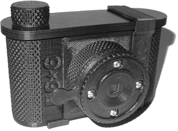
The fully functional P6*6 camera uses 120 roll film, comes in 35mm and 50mm lengths, and is printable without support even on the tiniest of print beds.
Written and photographed by Todd Schlemmer

is a firefighter/paramedic living in Seattle. He has studied paleontology and broadcasting, and has worked as a chef, a Birkenstock store manager, and a developer support engineer at Microsoft. His hobbies include 3D printing, photography, writing, computers, robotics, boatbuilding, auto mechanics, ham radio, and cooking. Todd is currently assembling a Shapeoko CNC router kit and lusts for a laser cutter.
THE P6*6 IS A 3D-PRINTED PINHOLE CAMERA, glued and fastened together with 3mm nuts and bolts. All of the individual parts print without support and fit on a 6-inch square print bed. The files are available for download from thingiverse.com/thing:157844.
The P6*6 comes in two focal lengths, 35mm and 50mm. It uses 120 roll film and makes an impressive 6cm square negative — roughly 4 times larger than a negative from a standard 35mm camera. 120 film is widely available and can be found at camera stores that cater to professional photographers or from internet vendors.
1. Print your camera parts
Download the 3D files from Thingiverse and print the camera parts (Figure 1):
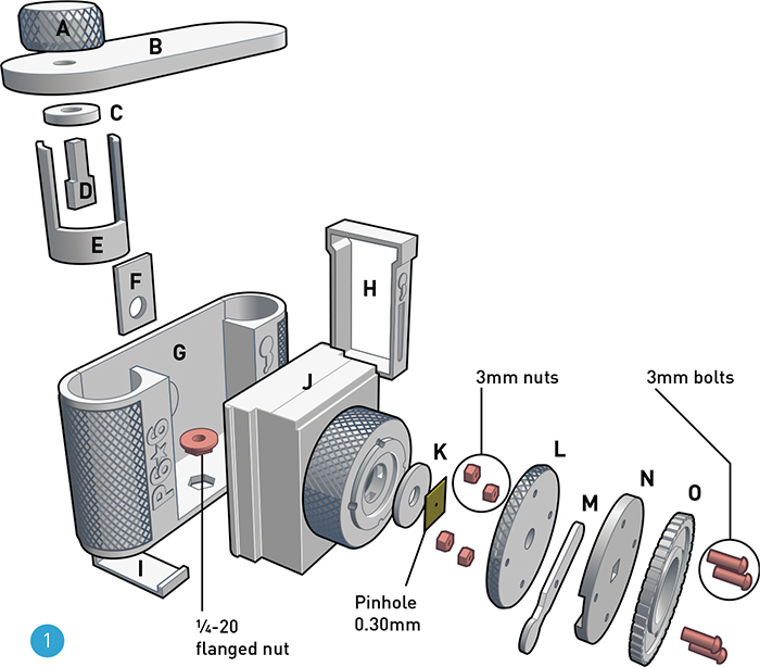
» A — Knob, used to advance the film
» B — Cap, snaps onto the body
» C — Baffle
» D — Winder, engages the take-up spool
» E — Film clip, keeps film tightly wound on the spool during unloading
» F — Frame slide, allows viewing of frame number on film backing
» G — Body
» H/I — Body clip and leveling spacer, prints as joined pieces
» 120 film, 6×6 format
» 50mm focal length:
• f-stop of f/167 with 0.30mm pinhole
• 62 degree vertical and horizontal angles of view
» 35mm focal length:
• f-stop of f/135 with 0.26mm pinhole
• 77.4 degree vertical and horizontal angles of view
P6*6 PINHOLE CAMERA PARTS
The P6*6, as illustrated, consists of 15 3D-printed parts.
» J — Extension, 50 mm or 35 mm length
» K — Pinhole disc, replaceable pinhole mount
» L — Pinhole clamp
» M — Shutter blade
» N — Shutter clamp
» O — Trim ring
When preparing the STL files for printing, use the following slicing settings:
» 0.25mm layer height
» 2 perimeters (or “shells”)
» 3 solid layers top and bottom
» 50% infill
2. Smooth and fit the printed parts
Every joint between parts in the P6*6 has a potential for photo-ruining light leaks —unintended openings that allow light into the camera. Careful attention to fit will ensure awesome photos. If necessary, use fine sandpaper or a file to smooth mating surfaces.
Carefully enlarge bolt holes with a ⅛" drill bit.
Pay special attention to the frame surface, formed by the bottom of the extension — the film slides across this surface when winding, and it forms the margin of your photographs. Surface irregularities could scratch the film, and an unevenly trimmed inside perimeter will be preserved as an uneven border on every photograph you make. Additionally, slightly round and smooth the bevel edge of the frame to avoid scratches on the film (Figure 2).

Before proceeding, check the fit of all mating parts. Refer to the exploded parts diagram. All parts should fit together without distorting. The cap should fit the body securely. The shutter blade should be slightly snug between the pinhole clamp and the shutter clamp.
Time Required:
90 Minutes
Cost:
$12
» 3D-printed parts see Step 1
» Nuts, 3mm (4)
» Bolts, 3mm×15mm long (4)
» Washers (4) (optional)
» Flanged nut, ¼-20 for tripod mount
» Adhesive-backed velvet or similar to “trap light” that would leak through joints in the assembly
» Translucent red plastic, 15mm–18mm disc A cheap plastic binder is a good source.
» Thin sheet metal with 0.26mm or 0.30mm pinhole
» Black permanent marker for back of pinhole (no internal reflections!)
» 3D printer (optional) with black ABS or PLA filament other colors will require flat black paint on interior surfaces. To find a machine or service you can use, see makezine.com/where-to-get-digital-fabrication-tool-access
» Flat files, large and small
» X-Acto/hobby knife
» Sandpaper, 500-1000 grit
» C-clamp or rubber bands
» Allen wrenches, small for bolts, and for manipulating tiny nuts inside the extension when assembling the shutter
» Drill with ⅛" bit
» Epoxy, dark such as JB Weld
» Super glue aka cyanoacrylate (CA) glue
» ABS plumbing glue, black for ABS only
» Plastruct “Plastic Weld” will bond all manner of plastics

NOTE:
RELAX — The pinhole is not as critical as it seems. You can purchase a precisely laser-drilled pinhole on the Internet or easily make your own from brass shim stock, a soda can, pie plate, etc. (Aluminum foil is too fragile.)
3. Final assembly
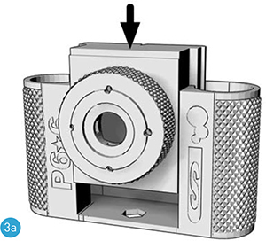
TRIPOD MOUNT
A ¼-20 nut is the standard tripod attachment. Carefully bond the flanged nut in its hexagonal hole in the body (Figure 3a), flush with the bottom of the body, using a bit of epoxy on the inside.
CAP AND WINDER
Parts A, B, C, and D (see Figure 1).
The winder drive passes through the baffle and cap and into the knob. This is designed to be a friction fit. If the narrow part of the winder drive is slightly too large to fit through the baffle into the knob, enlarge the holes rather than reducing the size of the winder shaft.
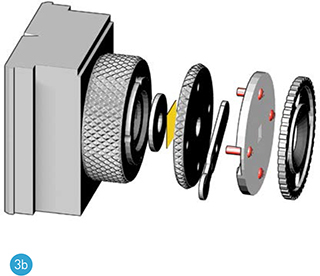
EXTENSION AND PINHOLE/SHUTTER
Parts J, K, pinhole, L, M, N, O, nuts, bolts, and (optional) washers. See diagrams.
Everything should fit together tightly prior to fastening. The extension, pinhole clamp, and shutter clamp must fit without interference (Figure 3b).
Bolting all these parts together can be a bit fiddly, but it’s important to assemble them before gluing the extension and body together. A small Allen wrench is handy to position the nuts in the nut traps (in the extension) during assembly (Figure 3c). The shutter should snap open and closed. It is easy to overtighten the bolts. Use super glue to mount the trim ring on the face of the shutter clamp.

VELVET LINING AND RED WINDOW
For best results, the inside back of the body can be lined with velvet behind the frame. The velvet provides a gentle friction that keeps the film in place and serves to reduce the effect of stray light from the frame index window. Lining the inside surface of the cap also minimizes light leaks (Figure 3d).
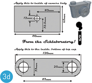
Download the self-adhesive velvet dimensions from thingiverse.com/thing:157844
Cut a 15mm–18mm disc of transparent red plastic, and tack it in place in the recess inside the body with a couple tiny dabs of super glue. The hole in the middle of the adhesive-backed velvet will overlap the disc and secure it in place. Carefully use the tip of an X-Acto blade to slide the velvet into position when attaching it to the body and cap. It must be wrinkle free.
BODY/EXTENSION JOINT
“Dry-fit” the extension and body before gluing them together. They’ll only fit one way — the “50” (or “35”) marking will be visible. Any interference could mean light leaks. The tripod nut must fit without difficulty. Resolve any issues before you glue.
During gluing, space the frame surface about 0.50mm away from the velvet (Figure 3e). You can use 5 sheets of printer paper (0.10mm thick each).

Mind the gaps! A proper fit looks like this.
TIP: For best results, assemble the shutter and extension first.
IMPORTANT: There is a gap between the extension and the body on each side when the 2 parts are properly fitted (Figur e3e).
GLUING
For ABS, plumbing cement works well (and comes in camera black). Work fast — the solvent evaporates quickly and the cement gets rubbery.
For bonding PLA, a dark epoxy is best, but gap-filling super glues or “Plastic Welder” type glues also give good results.
Follow the directions on the label. Too much glue will ooze out of the joint and muck up your lovely camera’s appearance. Use a C-clamp or stout rubber bands to precisely clamp the 2 parts together.
Allow the glue to dry, load your new camera with 120 film (Figure 3f), slide the body clip onto the camera, and make some pinhole photographs (Figure 3g)! ![]()


3 FUN THINGS TO 3D Print
Written by Eric Chu
1. Low-Poly Bulbasaur by Agustin Flowalistik thingiverse.com/thing:327753

This low-polygon representation of Bulbasaur from the Pokémon series really captures the essence of the little monster. Flowalistik is designing more, so follow him to catch (and print) them all.
2. Fuzzy Bear by Robo (Remixed from Ice Bear by Virtumake)
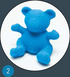
A fuzzy, high-polygon texture was applied to this bear using Blender. It provides a tactile experience that feels great in the hand. Try printing with different materials to get different feels.
3. Lolly Box by Faberdasher
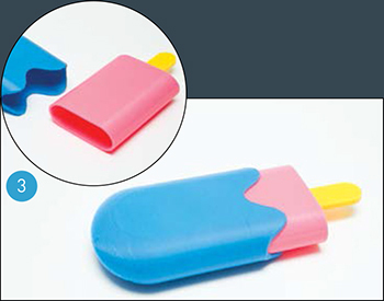
youmagine.com/designs/lolly-box
This 3-piece stash box in the form of a popsicle (or ice lolly, as it’s known as in the UK and Ireland) is perfect for those sunny days.