
PROJECTS
#makeprojects
Luminous Lowtops
Take light-up sneakers to the next level with full-color LEDs that respond to your moves.
Written by Clayton Ritcher
CLAYTON RITCHER (claytonritcher.com) is a double-major student (electrical and computer engineering, and robotics) at Carnegie Mellon University who enjoys coding, tinkering, and building things. He was born in San Antonio but calls Atlanta home. He’s also the creator of the Raspberry Rover (makezine.com/rasprover).

Time Required:
A Weekend
Cost:
$200–$240
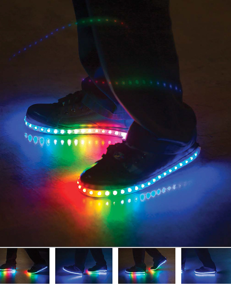
Stunning show of light and motion leaves other LED shoes in the dark ages.
THE LIGHT-UP SHOES FROM YOUR CHILDHOOD ARE ALL GROWN UP
— these Luminous Lowtops are force-sensitive, full-color LED light-up shoes for adults. Each shoe has two embedded force-sensitive resistors (FSRs) — one under the heel and one under the ball of the foot — and up to 40 RGB LEDs that change color based on the force readings, giving brilliant visual effects when you walk, stomp, jump, or lean.
Not long ago I saw a little boy stomping around a store in his light-up shoes. Admittedly jealous, I searched online for adult light-up shoes. Disappointingly, none of them responded to how you moved, only to the fact that you moved. Also, most of them required a battery pack to be strapped to the leg or shoe, rather than putting it inside like the kids’ shoes do. With those issues in mind, I decided to make the Luminous Lowtops.
The electronics are as simple as possible, to allow everything to fit within the shoe. The LEDs are individually addressable, so each one can be a different color at the same time, allowing the shoes to show shifts in weight and react to your movements. An Arduino Mini microcontroller reads an analog input from the front and rear FSRs, converts these values into colors and maps them to the front and rear LEDs, then calculates a color gradient for all the LEDs in between.
Each shoe is powered by 3 rechargeable AA batteries under the heel, and the components are embedded under the insole for a clean look. The LED strip is securely sewn to the exterior of the shoe, so you can jump, dance, or just gaze at the changing colors.
1. Prepare the shoes
There are 2 good mounting options for the batteries and Arduino. Mounting them on top of the tongue of the shoe is easiest, but they’ll be more visible there.
To hide the components inside, choose shoes with a thick insole. This allows for some of the padding to be cut out and replaced with the 3×AA battery pack. Rip out the insoles and strip all extra padding off of them, leaving just a thin layer.
Save the extra padding you remove in this step, as you might want to replace some of it later for comfort.
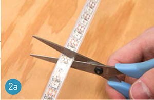
2. Attach the LEDs
Using scissors, cut the LED strips to the proper length to wrap around the perimeter of each shoe. The SparkFun and NeoPixel strips can be cut between any 2 LEDs (Figure 2a); just avoid the copper contacts. Cut the Adafruit #306 strip along the lines that appear after every second LED.
Use a needle (with thread that matches your shoes) to sew the LED strip to the shoe. To do this, loop the thread from the inside of the shoe, out through the edge of the LED strip, and back through the opposite edge of the strip into the shoe (Figure 2b). Pull this loop tight and tie a knot.

Repeat this process about once every inch along the shoe’s perimeter.
» Shoes (2) ideally with thick insoles
» RGB LED strips, 1 meter, individually addressable (2) SparkFun #COM-12027, 60 LEDs per meter. You can also use the inexpensive Adafruit NeoPixel strips, or the older Adafruit #306 (32 LEDs/meter).
» Sewing kit
» Arduino Pro Mini 328 microcontroller boards, 5V, 16MHz (2)
» FTDI Basic Breakout board, 5V
» Force-sensitive resistors, FlexiForce, 100lb rating (4) from tekscan.com. Make sure to buy the 100 pound model. If your shoe size is too small to fit the 8" sensor, buy a shorter size for a bit more money.
» Resistors, 1MΩ (4)
» Hookup wire, stranded insulated, 22 gauge
» 3-pin strip headers, female, 0.1" spacing (2)
» Batteries, NiZn rechargeable, AA size (6) Normal AA batteries provide 1.2V, but NiZn AAs provide 1.7V, so only 3 are needed to supply 5V, helping them fit in the shoe. You can also try AAAs; they fit into shoes easily, but won’t last as long.
» Battery packs, 3×AA (2)
» Battery chargers, NiZn AA (2)
» Cotton padding or cotton balls
» Battery packs, 2×AAA (2) (optional) to hide the Arduino Minis
» Scissors
» Drill or high-speed rotary tool such as a Dremel
» Wire cutters / strippers
» Soldering iron and solder
» Duct tape or packing tape
» Hot glue gun (optional) to mount the Arduino
» Computer running Arduino IDE free download from arduino.cc
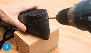
3. Drill the shoes
Drill a small hole through the back of each shoe, so that it emerges under the insole. This will allow wires from the Arduino and battery pack inside to reach the LED strips outside.
4. Build the circuit
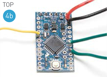
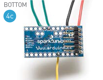
Following the wiring diagram (Figure 4a), solder together the circuit for each shoe.
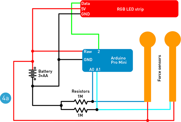
The wires from the Arduino to the LED strips need to be about half the length of the shoe; the wires to the force sensors should be about three-quarters of the length of the shoe. Cut them longer than you think you need; you can always shorten them later (Figures 4b and 4c).
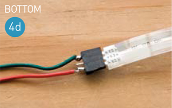
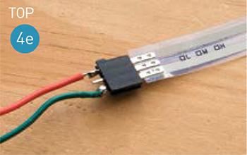
Don’t solder directly to the force sensors, as they are plastic and could melt. Instead, solder to a 3-pin female strip header, and then plug the force sensor into the header (Figures 4d and 4e). The middle pin of the force sensors isn’t used.
While you’re at it, solder the included headers to the FTDI breakout board.
5. Program the Arduino
Download the project code from makezine.com/projects/luminous-lowtops and open it in the Arduino IDE:
» If you’re using SparkFun or NeoPixel LEDs, use the Neopixel.ino sketch and download Adafruit’s Arduino library for NeoPixel LED strips from github.com/adafruit/Adafruit_NeoPixel.
» If you’re using Adafruit #306 LEDs, use the 8806.ino sketch and Adafruit’s library for LPD8806 LED strips from github.com/adafruit/LPD8806.
Under the Tools → Board menu, choose Arduino Mini w/ATmega328. Also, under Tools → Serial Port, select the serial port that your board is plugged into.
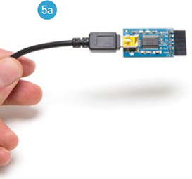
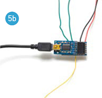
Plug the FTDI breakout board into your computer and plug its header pins into the corresponding 6 pins on the end of the Arduino Pro Mini (Figures 5a and 5b).
Count the LEDs on your shoe and update the nLEDs variable in the sketch with that number. (The default is int nLEDs = 40.) Click Upload in the Arduino IDE. Unplug the Arduino board.
Repeat for the second Arduino Mini.
6. Mount the force sensors
Use duct tape or packing tape to mount 2 force sensors inside each shoe, on top of the sole, so that the circular pad of one force sensor is under the ball of your foot, and the pad of the other sensor is under your heel (Figures 6a and 6b).
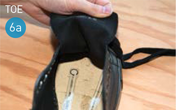
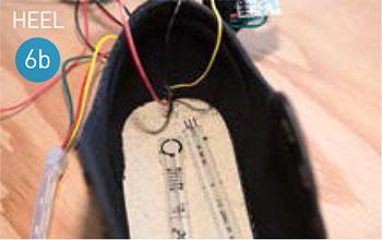
Run the wires and resistors flat along the bottom of the inside of the shoe.
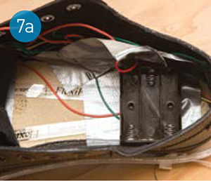
7. Mount the battery pack and Arduino
Tape the battery pack on top of the heel force sensor so that it fits comfortably under your heel (Figure 7a). I rip out any extra padding under the heel first. Most shoes have a hard pad under the heel to lift it; the battery pack essentially replaces this.
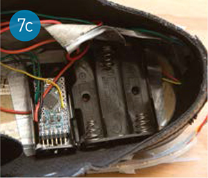
The Arduino should lie flat, just forward of the battery pack but tucked close to it, so that the batteries take your weight, not the Arduino (Figure 7b). Cover it with a bit of cotton padding or a cotton ball to protect it and to prevent it from poking you. Once you’re sure the shoes are working great, you can seal the Arduino in with hot glue. Or you can stash it in an empty 2×AAA battery pack for extra protection (Figure 7c).

Replace the insole to cover the electronics and battery pack. Though you’ve thinned it out, it still offers a bit of a cushion.
If your shoes don’t have room for these components under the heel, you can mount them on top of the tongue, above the area where your foot flexes (Figure 7d). Again, you can protect the Arduino by hiding it in an 2×AAA battery pack.

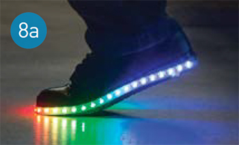
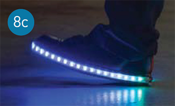
8. Power up the shoes
Charge the 6 NiZn AA batteries and place them in the battery pack of each shoe.
Put the shoes on, lace them up, and watch as they react when you walk, run, jump, and dance (Figures 8a, 8b, and 8c)!

The basic code loop reads an analog input from the front and rear force sensors (their resistance changes linearly with the amount of force, and they’re connected to the Arduino with pull-down resistors). It then takes those force values and scales them to the color space of the LEDs based on some general estimates of the maximum and minimum resistances of the force sensors.
Once the code has calculated the corresponding colors for the front and rear LEDs, a for loop produces a color gradient of sorts for all the LEDs in between.
Finally, the code sends these color values to the individual LEDs.
Going Further
To improve the fit with the components mounted inside the shoe, try excavating a cavity in the top of the sole to accept the battery pack and Arduino.
Try modifying the getColorFromForce function in the code so that the default color (with no weight on the sensors) is your favorite color. You might also save power (and extend run time) by switching the default from blue to red.
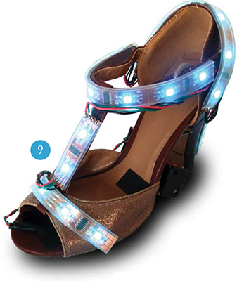
You could easily apply the techniques and code from this project to modify other kinds of shoes, like these light-up high heels (Figure 9), or other garments altogether. What about light-up elbow or knee pads? Light-up gloves? Pants? ![]()
Get the code, instructions, photos, and video at makezine.com/projects/luminous-lowtops