
10. Selection, Scale-Up, Operation, and Control of Bioreactors
Chapter 9, “Operating Considerations for Bioreactors for Suspension and Immobilized Cultures,” focused on idealized descriptions of homogeneous bioreactors with regard to operating mode (batch, fed-batch, continuous, and multistage) and generalized discussions of heterogenous reactors (immobilized cell systems and solid-state fermentation [SSF]). Real processes demand greater insight into the details of reactor configuration. It would be impossible in a book of this type to provide all the information necessary to become a design engineer, but this chapter introduces some of the concepts that drive the choice of real bioreactors. Our focus is primarily on reactors for bacteria and fungi; some of the special reactor issues for animal and plant cell tissue culture are handled in Chapter 12, “Bioprocess Considerations in Using Animal Cell Cultures,” and Chapter 13, “Bioprocess Considerations in Using Plant Cell Cultures.”
10.1. Scale-Up and its Difficulties
Why would the performance of a fungal culture making an antibiotic be so different at 10,000 l than at 10 l? At first glance, it might be unclear why performance should change with scale. The answers lie in the difficulty of maintaining homogeneity in large systems, changes in surface-to-volume ratios, and changes in the cultures themselves due to differences in microenvironments. To understand the problems in scale-up, we first need to describe what traditional culture vessels are and how they are operated.
10.1.1. Overview of Traditional Reactor Types
Rather than listing the large array of suggested fermenter and bioreactor designs, we restrict ourselves to considering some basic types:
• Reactors with internal mechanical agitation
• Bubble columns, which rely on gas sparging for agitation
• Loop reactors, in which mixing and liquid circulation are induced by the motion of an injected gas, by a mechanical pump, or by a combination of the two
Although fermenter and bioreactor are often used interchangeably, some professionals use “bioreactor” primarily for animal cell cultures. Here we use “fermenter” to refer to microbial or fungal cultures and “bioreactor” as a broad term incorporating any system for cultivating living cells.
All three reactor types (see Figure 10.1 for schematics) invariably are concerned with three-phase reactions (gas–liquid–solid). The reactors described here are made from materials that allow repeated use. Three-phase reactors are difficult to design, because the mass transfer of components among the three phases must be controlled. Inadequate tools for the complex fluid mechanics in such systems coupled with the complex nature of cells as reactive solids make the prediction of system performance very difficult.
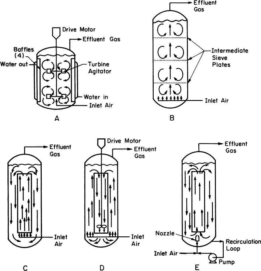
Figure 10.1. Bioreactor types. (a) Stirred-tank reactor, (b) bubble-column reactor, (c) airlift loop reactor with central draft tube, (d) propeller loop reactor, and (e) jet loop reactor. Arrows indicate fluid circulation patterns. (With permission, from D. N. Bull, R. W. Thoma, and T. E. Stinnett, Adv. Biotechnol. Processes I, 1, 1985, and Alan R. Liss, Inc., New York.)
10.1.2. Reactors with Internal Mechanical Agitation
$$$The traditional fermenter is the stirred-tank reactor (Figure 10.2), the prime example of a reactor with internal mechanical agitation. The main virtues of such systems are that they are highly flexible and can provide high kLa (volumetric mass-transfer coefficient) values for gas transfer. Stirred reactors of up to 400 m3 are used in antibiotic production, with stirrer powers of up to 5 kW/m3. Stirred reactors can be used commercially up to viscosities of about 2000 centipoises (2 Pa sec). Stirred-tank systems for animal and plant cell culture are typically much smaller than for microbial systems. A reactor of 20 m3 is the upper limit used for animal cells and 75 m3 for plant cells.
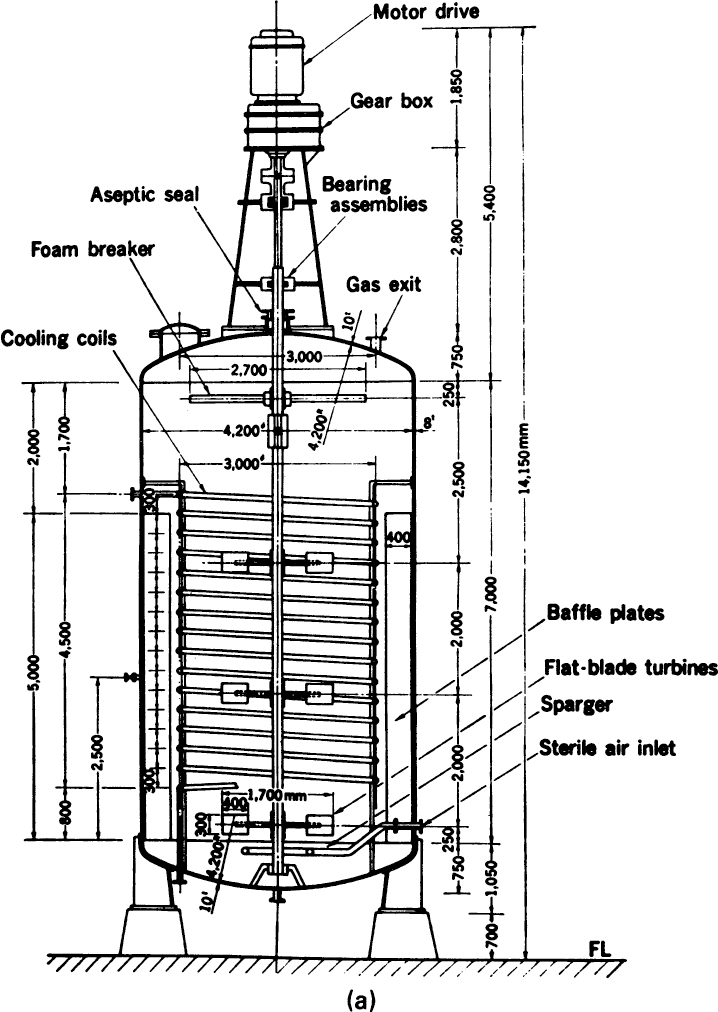
Figure 10.2. (a) Mechanically stirred 100,000-liter fermenter. (With permission, from S. Alba, A. E. Humphrey, and N. F. Millis, Biochemical Engineering, 2d ed., University of Tokyo Press, Tokyo, 1973.)
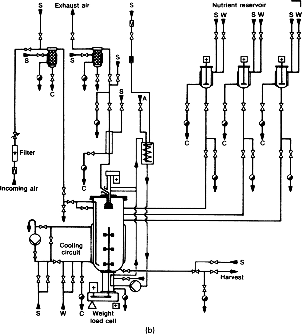
Figure 10.2. (b) Installation of mechanically stirred fermenter: S, steam, C, condensate, W, water, and A, air. The steam lines permit in-place sterilization of valves, pipes, and seals. The input air can be sterilized by both incineration and filtration. (With permission, from W. Crueger and A. Crueger, Biotechnology: A Textbook of Industrial Microbiology, R. Oldenbourg Verlag, München, Germany, 1984. With permission from Science Tech Publishers.)
Gas under pressure is supplied to the sparger (usually either a ring or disk with holes or a tube with a single orifice). The size of the gas bubbles and their dispersion throughout the tank are critical to reactor performance. Although a sparging ring will initially provide smaller bubble size and better gas distribution, spargers with a single discharge point are more resistant to plugging.
Gas dispersion is a function not only of the sparger but also of the impeller. The impeller must provide sufficiently rapid agitation to disperse bubbles throughout the tank, to increase their residence time within the liquid, and to shear larger bubbles into small bubbles. Too much stirring can be detrimental, owing to the shear sensitivity exhibited to varying degrees by some cells (e.g., animal cells) and the stratification of reactor contents with multiple-impeller systems. Although a wide variety of impeller designs have been proposed, the predominant choices are disk and turbine impellers, and for cellular systems with high levels of shear sensitivity, marine and paddle impellers are of particular interest.
The Rushton impeller (Figure 10.3) is a disk with typically six to eight blades designed to pump fluid in a radial direction. Until the mid-1980s, the Rushton impeller was the predominant design choice, and it is commonly found on industrial and laboratory fermenters. The axial flow hydrofoil impellers have become increasingly popular. Axial flow systems can pump liquid either down or up. They have been shown to give superior performance (compared to Rushton radial flow impellers) with respect to lower energy demands for the same level of oxygen transfer. Further, they show reduced maximum shear rates, making them usable with sensitive cultures such as animal cells, while still being capable of excellent performance with viscous mycelial fermentations. Axial flow systems break up the compartmentalization often observed with multiple radial flow impellers on the same shaft. Combinations of axial flow and radial flow impeller systems are sometimes used. To augment mixing and gas dispersion, baffles are employed. A typical arrangement includes four baffles, the width of each being about 8% to 10% of the reactor diameter. With animal cell cultures, baffles cause shear damage; instead of baffles, bottom-drive axial impellers slightly offset from center can be used.
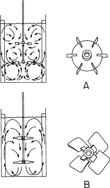
Figure 10.3. Liquid flow in bottled tanks with (A) Rushton radial flow impellers and with (B) axial flow hydrofoil impellers.
The vessel itself is almost always stainless steel. Type 316 is used on all wetted parts, type 304 on covers and jackets. With plant and animal cell tissue cultures, a low-carbon version (type 316L) is often used. Many bench-scale fermenters are glass vessels with stainless-steel cover plates. Glass fermenters are rarely used at the 50 l scale, and material considerations limit the maximum size of glass vessels to about 500 l. The use of stainless steel and glass is called for by the need to sterilize the reactor and the corrosive and/or abrasive nature of many fermentation media.
Most fermenters are built with a height-to-diameter ratio of 2 to 3, although for animal cell bioreactors this ratio tends to be closer to 1. The Rushton impeller diameter is typically 30% to 40% of the tank diameter, whereas for the axial flow hydrofoil impellers it may reach 50%. In large reactors, the two main limitations on size are the abilities of the design to provide an adequate supply of oxygen and to remove metabolic heat efficiently. Large reactors usually use either internal coils for heat removal or a jacketed vessel. Although copper coils have better thermal transport characteristics, stainless-steel coils are almost always used, but this choice can depend on the nature of the media and culture. Internal coils provide advantages over jacketed vessels in terms of efficiency of heat removal, owing to the larger surface area for heat transfer. However, in many systems, the coils become rapidly fouled by microbial growth, decreasing heat transfer and often adversely affecting mixing and maintenance of sterility. In such cases, the jacketed vessels offer advantages.
Another problem often encountered in commercial fermentations is foaming. If foam escapes from the fermenter, it can wet filters, increasing pressure drop and decreasing gas flow. Of greater concern is that it provides a pathway for contaminating cells to enter the fermenter. For most products of commercial interest, absolute sterility is required, and contamination may cause the loss of much product, time, and money. Foam can be controlled with a mechanical foam breaker or the addition of surface-active chemical agents. Although such chemicals can be very effective in controlling foam, there are penalties. Foam-breaking chemicals usually lower kLa values, reducing the reactor’s capacity to supply oxygen or other gases, and in some cases they can be inhibitory to cell growth. Foam formation is not well understood, but complex media or the formation of high levels of extracellular polymers (e.g., proteins) tend to promote foaming. Foam can limit the ultimate productivity of a fermenter. All stirred-tank fermenters provide head space for the gas to disengage from the liquid. The working volume (the amount of culture) in a fermenter is typically about 75% of the total fermenter volume.
Sterility is a prime design consideration for fermenter hardware. Pressurized steam is used for in-place sterilization of the reactor, seals, probes, and valves. The number of openings into the fermenter should be limited to what is essential. A trade-off is necessary between the use of many probes, which improves fermenter control, and of few probes, which improves the chances of maintaining sterility. Small openings are made leakproof with O-rings, while flat gaskets are satisfactory for larger openings. Although small fermenters can use magnetically coupled agitators, industrial-size fermenters have moving shafts that must penetrate into the fermenter. Prevention of contamination due to the entry of foreign organisms through such a shaft is a major challenge in the mechanical design of fermenters. Stuffing-box seals are common on old fermenters, while double mechanical seals are used in newer ones. All surfaces must be smooth. Crevices in the tank surface, pipes, and valves can trap large quantities of particulate organics and contaminating organisms. Such clumps of cells increase the chances for a contaminant to survive the sterilization procedure. Cleanability of all surfaces is important.
Cleaning is generally done “in place,” and fermenter design includes spray balls to allow for clean-in-place (CIP) technology. Highly alkaline detergents are often used, and this factor helps dictate the selection of materials. Surfaces, especially in bioreactors for animal or plant tissue cultures, often undergo electropolishing, an electrolytic process that removes the sharp microscopic projections often resulting from mechanical polishing. All ports and valves involved in sampling and injection should be protected with steam-sterilizable closures. The application of a continuous flow of live steam to sample valves is one strategy that is often applied in antibiotic plants.
10.1.3. Bubble Column and Loop Reactor
The same concern for sterility applies to bubble columns and loop (e.g., airlift) reactors. Bubble columns offer distinct advantages for some systems. They are suitable for low-viscosity Newtonian broths; satisfactory mixing may not be possible in highly viscous broths. Bubble columns provide a higher energy efficiency than stirred-tank systems; by energy efficiency we mean the amount of oxygen transferred per unit of power input. An additional advantage often mentioned for bubble columns is that they provide a low-shear environment, which may be a critical consideration with some cells. Cells tend to accumulate at the bubble surface, however, and bubble bursting is highly detrimental to cells. The absence of mechanical agitation also reduces cost and eliminates one potential entry point for contaminants.
Besides having less vigorous mixing capabilities than stirred tanks, bubble-column operation is often limited by considerations of foaming and bubble coalescence. Because of bubble coalescence, bubble columns work over a rather narrow range of gas flow rates. The range of appropriate gas flows varies with the nature of the broth. Thus, bubble columns are less flexible than stirred tanks. Partial relief from the problem of coalescence can be found by using multistage columns; each stage (perforated plate) acts to redistribute gas flow. This gas redispersion, however, carries an energy penalty.
Loop reactors have intermediate characteristics between bubble columns and stirred tanks. We consider primarily the airlift system (Figure 10.1) in which the motion of the gas carries fluid and cells up a draft tube. At the top, gas disengages from the liquid, and the degassed liquid (which is denser than the gassed liquid) descends in the annulus outside the tube. At the bottom of the reactor, the descending fluid again encounters the gas stream and is carried back up the draft tube. Airlift systems can generally handle somewhat more viscous fluids than bubble columns, and coalescence is not so much of a problem. The largest fermenter (1500 m3) ever built (by ICI) is an airlift design for the production of single-cell protein. With very large fermenters (>200 m3), the use of nonmechanically agitated designs is preferred, as high oxygen transfer rates and better cooling can be attained. With an airlift design, the interchange of material between fluid elements is small, so the transient time to circulate from the bottom of the draft tube to the top and back again is important. In the ICI design, multiple injection points for the substrate are used to prevent the cells from becoming substrate starved during circulation. The addition of mechanical stirring to a loop reactor increases flexibility (the operating range).
Although we focus our attention on agitated tanks, realize that most anaerobic fermentations (in terms of total volume) are conducted in nonstirred and nonaerated vessels. Such vessels are used often in food fermentations, such as for beer, wine, and dairy products (e.g., cheese). In anaerobic fermentations, gas evolution by the fermenting organisms can provide some mixing, but gases are not normally sparged into the vessel. However, agitated and/or aerated vessels are used on a wider variety of fermentations (in terms of number of processes), are more difficult to scale, and are more likely to be chosen for the production of new products.
10.1.4. Single-Use Bioreactors
During the last 15 years, industry has begun to use single-use (or “disposable”) bioreactors instead of traditional reusable systems. The use of these systems is focused on high-value products such as those typically produced from animal cell culture where reactor size is modest. Advances that have increased per-cell productivity can often support the use of bioreactors of modest sizes (order of 100 l) and are particularly attractive for human stem cells. However, this technology has been used with microbial systems as well.
Single-use bioreactors are typically made from FDA-approved plastics (e.g., polycarbonate, polystyrene, and others). The cultivation container is delivered preassembled and sterile and is “ready-to-use.” After use, the cultivation chamber is decontaminated and disposed. The advantages of this technology include rapid scale-up and implementation because sterilization/cleaning procedures and their validation are not required. Since the regulatory constraints on the pharmaceutical industry, particularly concerning cleanliness, are so demanding, single-use technology offers a major advantage. It also leads to great process flexibility and responsiveness to market changes, reduced costs (particularly initial capital costs are reduced several-fold), and improvements in biosafety. There are potential disadvantages in terms of issues with chemicals that may leach out of the plastic and contaminate the product and the mechanical stability of the plastic. Also limiting is the oxygen transfer capability of disposable systems as well as the degree of mixing, which limits the effective cell concentration attainable. Sensor technology for use in disposables lags and is another limitation. The maximum size is order of 2 m3 (2000 l), although efforts are being made to increase the maximum useable size.
Disposable bioreactors typically are mechanically driven either by external or internal means. One example of an externally driven system is the use of a culture bag on a rocker platform (e.g., WAVE Bioreactor). The rocker can impact oscillatory movement, resulting in a “wave.” Other motions, such as rotary, vibrating, or “shaken” platforms, are possible. One category of internally driven systems involves the use of a culture bag with an internal rotating stirrer magnetically coupled to the external platform or a rigid cylindrical vessel with a mechanically coupled stirrer. Another category is vessels with pneumatically driven stirring. Hybrid systems with mechanical and prepneumatic-driven mixing also exist. While most of these systems are used primarily for animal cells, some (e.g., Saltus Bioreactor) use an oscillating hollow shaft that generates high shear conditions and cannot be used with shear-sensitive animal cells.
Disposable technology is being developed not only for bioreactors but for media and buffer preparation, filtration, and even chromatography. This trend is driven, in part, by the same issues as for the development of disposable bioreactors.
The principles for reactor design, based primarily on aeration, agitation, and heat transfer, are the same for disposable and permanent bioreactors, although details may vary due to differences in geometry and details of how oxygen enters and carbon dioxide exits the reactor. In the next section, we address these issues.
10.1.5. Considerations in Aeration, Agitation, and Heat Transfer
The basic equations describing oxygen transfer, carbon dioxide evolution, and heat generation by microbial growth are given in Chapter 6, “How Cells Grow.” For industrial-scale fermenters, oxygen supply and heat removal are the key design considerations.
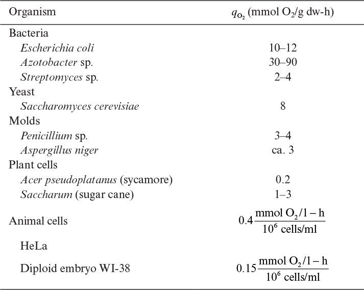
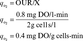
The severity of the oxygen requirements depends on the choice of organism. Equation 6.24 can be rewritten as
where qo2 is the specific uptake rate of oxygen (mol O2/g-h). Typical values of qo2 are given in Table 10.1. The value of qo2 (or oxygen uptake rate OUR) is the demand side of the equation; typical requirements in large-scale systems are 40 to 200 mmol O2/l-h, with most systems in the 40 to 60 mmol O2/l-h range.
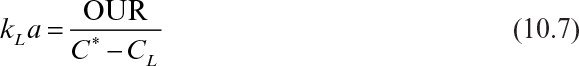
On the supply side, the critical parameter is kLa(h–1), the volumetric oxygen transfer coefficient. A wide range of equations has been suggested for the estimation of kLa. References at the end of this chapter detail some of these correlations. A typical correlation has the form
where k is an empirical constant, Pg is the power requirement in an aerated (gassed) bioreactor, VR is bioreactor volume, vs is the superficial gas exit speed, and N is the rotational speed of the agitator. With equations of the form of equation 10.2a, all the parameters must be in the units that are required by the correlation. Following is an example of one of the original correlations of this type (when partial pressures are used):
A value of Pg can be estimated from other correlations, such as the following:
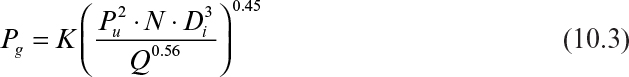
where K is a constant based on reactor geometry, Pu is the power required in the ungassed fermenter, Di is the impeller diameter, and Q is the aeration rate (volume of gas supplied per minute divided by the liquid volume in the reactor).
The preceding correlations are not very good for Newtonian systems and are even worse for non-Newtonian or highly viscous systems. They also neglect the effects of medium components on kLa. The presence of salts and surfactants can significantly alter bubble size and liquid film resistance around the gas bubble. These factors also can affect oxygen solubility (C*). Temperature and pressure also affect kLa and (C*). Finally, on the supply side, it should be noted that CL is maintained at a value above the critical oxygen concentration (see Chapter 6) but at a low enough value to provide good oxygen transfer. For many bacterial fermentations, a CL of about 1 mg/l provides a good margin of safety if mixing is incomplete and yet allows a good rate of oxygen transfer.
Although kLa is difficult to predict, it is a measurable parameter and can be measured for microreactors as well as large industrial fermenters. Four approaches are commonly used: unsteady state, steady state, dynamic, and sulfite methods. The way in which these methods are applied depends on whether the methods are used in the presence or absence of cells.
A new reactor, prior to operation, can be filled with pure water or a medium in which C* can be accurately measured. Oxygen is removed from the system by sparging with N2. With the unsteady-state method, air is then introduced and the change in dissolved oxygen (DO) is monitored until the solution is nearly saturated. In this case,

or

Integration of Equation 10.4b from t = 0 to t and CL = CLo to CL results in equation (10.5):
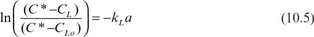
As shown in Figure 10.4, a plot of Ln ![]() versus time will give an estimate of kLa.
versus time will give an estimate of kLa.
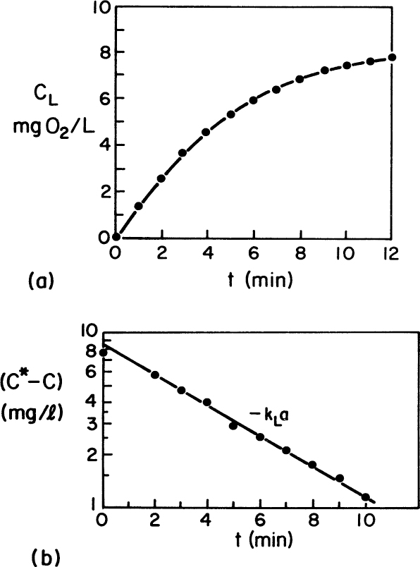
Figure 10.4. (a) Typical data for unsteady-state accumulation of oxygen in a large stirred tank. (b) Assuming C* = 8.65 mg O2/l, a value of kLa = 11.5 h–1 is determined. (D. W. Sundstrom, H. E. Klei, Wastewater Treatment © 1979.)
Another approach is the sulfite method. In the presence of CU2+, the sulfur in sulfite (![]() ) is readily oxidized to sulfate (
) is readily oxidized to sulfate (![]() ) by a zero-order reaction. This reaction is very rapid, and consequently, CL approaches zero.
) by a zero-order reaction. This reaction is very rapid, and consequently, CL approaches zero.
The rate of sulfate formation is monitored and is proportional to the rate of oxygen consumption (![]() mol of O2 is consumed to produce 1 mol of
mol of O2 is consumed to produce 1 mol of ![]() ). Thus,
). Thus,
where CSO4 is the concentration of ![]() . The factor,
. The factor, ![]() , requires that CSO4 and C* be expressed in terms of moles. Oxygen solubility, C*, is a constant dependent on medium composition, temperature, and pressure and can be measured separately:
, requires that CSO4 and C* be expressed in terms of moles. Oxygen solubility, C*, is a constant dependent on medium composition, temperature, and pressure and can be measured separately:
OUR is the oxygen uptake rate. The sulfite method probably overestimates kLa. Note that if the chemical reaction takes place in the liquid film around the gas bubble, the apparent oxygen transfer will be greater than that for a system with no chemical reaction in the liquid film. (An unresolved question is whether respiring organisms can enhance oxygen transfer by a similar method.)
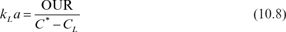
Perhaps the best way to determine kLa is the steady-state method, in which the whole reactor is used as a respirometer. Such an approach requires the accurate measurement of oxygen concentration in all gas exit streams and a reliable measurement of CL. A mass balance on O2 in the gas allows the rate of O2 uptake, OUR, to be calculated:
OUR could also be estimated with off-line measurements of a sample of the culture in a respirometer, but using information from the actual fermenter is ideal. However, one complication in this (and other methods) is determining what value of C* to use. In a large fermenter, gas is sparged under significant pressure (due at least in part to the liquid height in an industrial fermenter). C* is proportional to pO2, which depends on total pressure as well as the fraction of the gas that is oxygen. At the sparger point, pO2 will be significantly higher than at the exit, due to both higher pressure and the decrease in the fraction of the gas that is O2 because of consumption by respiration. In a bubble column, the log mean value of C* based on pO2 at the entrance and exit would be a justifiable choice. In a perfectly mixed vessel, the composition of gas in the exit stream should be the same as bubbles dispersed anywhere in the tank, and consequently C* would be based on pO2 at the exit. In an actual tank, a knowledge of the residence time distribution of gas bubbles is necessary to estimate a volume averaged value of C*.
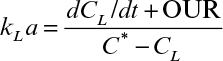
The dynamic method shares similarities with the steady-state method in that it uses a fermenter with active cells. It is simpler in that it requires only a DO probe and a chart recorder rather than off-gas analyzers as well as the DO probe required in the steady-state method. Following is the governing equation for DO levels:
or
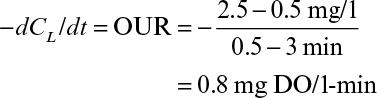
The dynamic method requires that the air supply be shut off for a short period (eq <5 min) and then turned back on. The anticipated result is shown in Figure 10.5. Since there are no gas bubbles when the gas is off, kLa will be zero. Hence,

Figure 10.5. Example of response of dissolved oxygen in a fermenter when stopping and then restarting air flow. The dynamic method can be used to estimate oxygen uptake rate and kLa.
The slope of the descending curve will give the OUR, or –qo2X. The lowest value of CL obtained in the experiment must be above the critical oxygen concentration (recall Chapter 6) so that qo2 is independent of CL. Further complications can arise due to the measurement lag in the DO probe (about 30 to 45 s) and the dissolution of oxygen from the headspace gas into the liquid (which may be significant primarily in small vessels, since the ratio of surface area for gas transfer is high compared to liquid volume). When air sparging is resumed, the ascending curve can be used to calculate kLa. Values of dCL/dt can be estimated from the slope of the ascending curve calculated at various time points. A plot of (dCL/dt + OUR) versus (C* – CL) results in a line with a slope of kLa. The primary advantage of the dynamic method is that kLa can be estimated under actual fermentation conditions. Additionally, if qo2 is known, the value of OUR can be used to estimate X.
Variations on these methods to determine kLa exist, but the general principles remain the same. However, once the oxygen transfer rate (OTR) can be estimated from either correlations or experimentally determined values kLa, it is possible to quickly estimate the rate of metabolic heat generation. Equation 6.26 provides such a relationship. Equations 6.24 to 6.26 apply in all cases and lead to an estimate of the rate of heat generation. The total amount of cooling surface (either jacket or coils) required can then be calculated, given the temperature of the cooling water, the maximum flow rates allowable, the desired temperature differential between the exiting coolant and the reactor, and the overall heat transfer coefficient. The latter presents the greatest problem, since it can vary greatly from fermentation to fermentation. Highly viscous fermentations, which decrease fluid mixing, obviously decrease the rate of heat transfer. Many fermentations will cause solids deposition on coils, greatly decreasing the heat transfer coefficient. In extreme cases, solids deposition can plug spaces between coils, greatly decreasing convective flow by coils and consequently the heat transfer coefficient. Cooling coils are usually placed so that high fluid velocities will strike the coils to promote cleaning. If a reactor is to be maintained as a highly flexible piece of equipment adaptable to a wide range of fermentations, very conservative estimates of the overall heat transfer coefficient must be made.
10.1.6. Approaches to Scale-Up
The discussion in the previous sections has revealed the complex nature of industrial bioreactors. Now we consider how these complexities affect approaches to scaling bioreactors.
Generally, bioreactors for fungal or microbial culture maintain a height-to-diameter ratio of 2 or 3. However, for animal cell bioreactors, this ratio may be 1. If the height-to-diameter ratio remains constant, then the surface-to-volume ratio decreases dramatically during scale-up. This change decreases the relative contribution of surface aeration to oxygen supply and dissolved-CO2 removal in comparison to the contribution from sparging. For traditional bacterial fermentations, surface aeration is unimportant, but for shear-sensitive cultures (e.g., animal cells), it can be critical because of restrictions on stirring and sparging.
More important in bacterial and fungal fermentations is wall growth. If cells adhere to surfaces, and if such adherent cells have altered metabolism (e.g., due to mass transfer limitations), then data obtained in a small fermenter may be unreliable in predicting culture response in a larger fermenter. This point is more clearly illustrated later in Example 10.2.
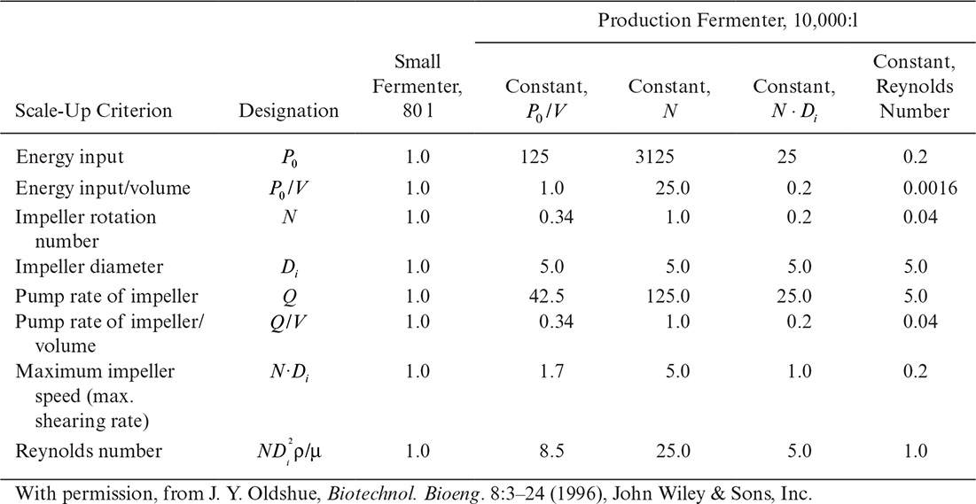
Perhaps even more importantly, it can be shown that the physical conditions in a large fermenter can never exactly duplicate those in a smaller fermenter if geometric similarity is maintained. In the case described in Table 10.2, a stirred-tank diameter has been increased by a factor of 5, resulting in a 125-fold increase in volume, since the height-to-diameter ratio was maintained constant. Four cases are treated in Table 10.2: scale-up based on constant power input (P0/V), constant liquid circulation rate inside the vessel (pumping rate of impeller per unit volume, Q/V), constant shear at impeller tip (N Di) and constant Reynolds number (![]() ). Note that
). Note that ![]() . Thus, fixing N and Di fixes all the quantities in Table 10.2. Since these quantities have different dependencies on N and Di, a change of scale must result in changes in the physical environment that the cells experience. When these changes alter the distribution of chemical species in the reactor, or they destroy or injure cells, the metabolic response of the culture will differ from one scale to another. In some cases, cells respond to modest changes in mechanical stress by changing physiological functions even when there is no visible cell injury or cell lysis. Thus, different scale-up rules (constant P/V implies constant OTR, constant Reynolds number implies geometrically similar flow patterns, constant N to give constant mixing times, and constant tip speed to give constant shear) can give very different results.
. Thus, fixing N and Di fixes all the quantities in Table 10.2. Since these quantities have different dependencies on N and Di, a change of scale must result in changes in the physical environment that the cells experience. When these changes alter the distribution of chemical species in the reactor, or they destroy or injure cells, the metabolic response of the culture will differ from one scale to another. In some cases, cells respond to modest changes in mechanical stress by changing physiological functions even when there is no visible cell injury or cell lysis. Thus, different scale-up rules (constant P/V implies constant OTR, constant Reynolds number implies geometrically similar flow patterns, constant N to give constant mixing times, and constant tip speed to give constant shear) can give very different results.
These scale-up problems are all related to transport processes. In particular, the relative time scales for mixing and reaction are important in determining the degree of heterogeneity in a fermenter. As we scale the system up, we may move from a system where the microkinetics (the cellular reactions) control the system response at small scale to one where transport limitations control the system response at large scale. When a change in the controlling regime takes place, the results of small-scale experiments become unreliable with respect to predicting large-scale performance.
One approach to predicting possible reactor limitations is the use of characteristic time constants for conversion and transport processes. Table 10.3 defines some of the important time constants, and Table 10.4 shows the application of these time constants to a 20 m3 fermenter for the production of gluconic acid.

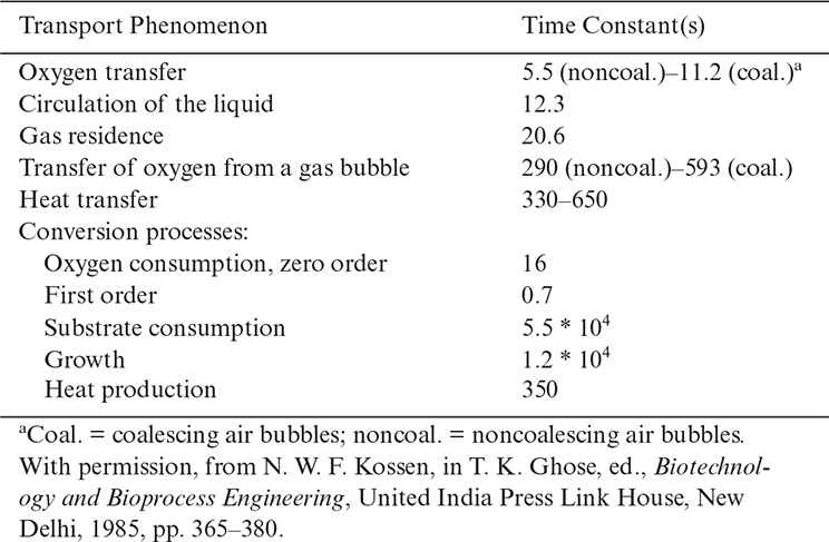
Processes with time constants that are small compared to the main processes appear to be essentially at equilibrium. If, for example, the oxygen transfer rate is much greater than the rate for oxygen consumption, then the broth would be saturated with oxygen. This situation occurs when 1/kLa << tO2 where tO2 is the time constant for O2 consumption. If, on the other hand, consumption is of the same order of magnitude as oxygen supply (i.e., 1/kLa ≈ tO2 conversion), the dissolved oxygen concentration may be very low. This is precisely the case in Table 10.4 and Figure 10.6. The resulting experimental measurements of dissolved oxygen show the great variability in oxygen concentration in the reactor with some values at zero. This heterogeneity means that cells pass periodically through anaerobic regions. Since many cells have regulatory circuits to respond to changes from aerobic to anaerobic conditions, these circuits may be constantly altering cellular metabolism.
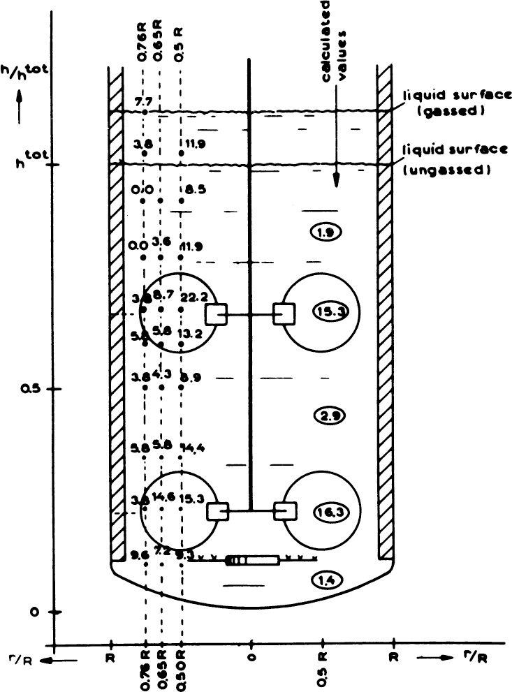
Figure 10.6. Measured oxygen concentrations in a 20 m3 production fermenter (figures in circles are model estimates). (With permission, from N. W. F. Kossen, in T. K. Ghose, ed., Biotechnology and Bioprocess Engineering, United India Press Link House, New Delhi, 1985, pp. 365–380.)
Traditional scale-up is highly empirical and makes sense only if there is no change in the controlling regime during scale-up, particularly if the system is only reaction or only transport controlled. Common scale-up rules are the maintenance of constant power-to-volume ratios, constant kLa, constant tip speed, a combination of mixing time and Reynolds number, and the maintenance of a constant substrate or product level (usually DO concentration). Each of these rules has resulted in both successful and unsuccessful examples (described in several of the references at the end of the chapter). Results are more favorable with Newtonian broths than with non-Newtonian systems.
The failure of any of these rules is related to changes in the controlling regime upon scale-up. No empirical rule can satisfactorily address such situations. Advances are being made in models that predict flow distribution, mixing times, and gas dispersion in fermenters, as well as models that predict explicitly cellular responses to changes in the local environment. If these models can be integrated, they may provide a much more fundamentally sound basis for scale-up. With the advent of improved supercomputers, the computational demands of such sophisticated models can be met. An approach to estimating mixing times in a stirred fermenter is given later in Example 10.4.
It has been shown empirically for fermenter volumes of 0.1 to 100 m3 that mixing time can be correlated to reactor volume according to an expression such as†:
† B. C. Buckland and M. D. Lilly, in Biotechnology 2d ed., H.-J. Rehm and G. Reed, Vol 3, G. Stephanopoulos, VCH, New York, 1983, pp. 12–13.
where tm is mixing time and V is vessel volume. The constant, Tk, is a function of impeller type, placement, and vessel design. Equation 10.11 assumes multiple Rushton-type impellers and is based on data from vessels of different sizes at practical operating conditions.
In summary, scale-up as currently practiced is an empirical, imprecise art. As long as geometric similarity is demanded at various scales, microenvironmental conditions cannot be made scale independent. Models and the use of scale-down procedures are potential approaches to improving scale-up, but these approaches are not yet fully developed.
The nature of the practical operating boundaries for an aerated, agitated fermenter can be summarized as in Figure 10.7. The exact placement of such boundaries depends on the fermentation and change as the system is scaled up or scaled down. The boundaries are fuzzy rather than sharp. Nonetheless, the bioprocess engineer must appreciate the existence of such constraints.
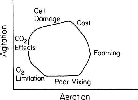
Figure 10.7. Practical operating boundaries for aerated, agitated fermenters. (After Lilly, M. D., 1983, in Bioactive Microbial Products 2; D. J. Winstanley and L. J. Nisbet, eds., Academic Press, London, pp. 79–89.)
There are practical limits to the maximum size of a bioreactor based on both materials issues and transport limitations. Scale-up then requires the use of multiple reactors. In the pharmaceutical industry, these are often operated in parallel because batch operation is generally preferred due, in part, to regulatory issues. As described in Chapter 9, multistage or cascades of reactors are possible. Although cascades alter reaction kinetics (e.g., making the system operate more like a plug flow system than a well-mixed system), they also allow larger reaction systems to be constructed. Such multiscale systems are found in wastewater treatment and for production of chemicals such as ethanol for use as a fuel.

D = 10.8 cm
S = 738 cm2
V = 2000 cm3
D = 233.5 cm
S = 342,600 cm2
V = 2 × 107 cm3
342,600 cm2/738cm2 × 2g = 928g
2g/1·21= 4g
928 g + (2 g/1·![]() ·20,000 1) =20,928 g
·20,000 1) =20,928 g
10.1.7. Scale-Down and Microbioreactors
Although scale-up models and the use of characteristic time analysis are potentially attractive, a more immediate approach to the rational scaling of reactors is scale-down. Recently there has been increased interest in mini- and microbioreactors to explore factors that influence scale-up of bioprocesses more cheaply and effectively than in macro-scale bioreactors. The basic concept is to provide at a smaller scale an experimental system that duplicates exactly the same heterogeneity in environment that exists at the larger scale. In many cases, scale-up will require using existing production facilities, so it is important to mimic those production facilities at a smaller scale. At the smaller scale, many parameters can be tested more quickly and inexpensively than at the production scale. Also, such a small-scale system can be used to evaluate proposed process changes for an existing operating process and to select a range of possible operating conditions for a new process.
Figure 10.8 is a sketch of a smaller-scale apparatus to approximate the types of variations in substrate and DO concentrations that might be expected from a mixing-time analysis (or from estimates from time constants) or from actual data on residence-time distributions from a large reactor. The difference between this scale-down apparatus and a traditional smaller-scale fermenter in a pilot plant is that the type of apparatus described in Figure 10.8 is constructed specifically to mimic a known piece of equipment. It should be noted that the apparatus in Figure 10.8 would not mimic temperature heterogeneity as it might exist in the larger system. Modifications to control temperature separately in each subvessel could be made.

Figure 10.8. Experimental setup for scale-down experiments. (With permission, from N. W. F. Kossen, in T. K. Ghose, ed., Biotechnology and Bioprocess Engineering, United India Press, New Delhi, 1985, pp. 365–380.)
Such a scale-down apparatus could be used to estimate the system’s response (e.g., growth rate, product formation, and formation of contaminating by-products) to changes in medium composition (e.g., a new supplier of raw materials), introduction of modified production strains, use of different inoculum preparations, new antifoam agents, and for testing for O2 and CO2 tolerance. Corrective protocols can be suggested also for use in the large-scale system by simulating the response to pH or oxygen-probe failure or compressor failure during different phases of the fermentation.
Construction of scale-down apparatus can be a powerful complement to mathematical models, scale-up rules, and traditional pilot-plant operation.
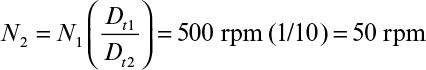
a. Constant P/V
b. Constant impeller tip speed
c. Constant Reynolds number
Dt = 16.2 cm
H = 48.6 cm
Di = 4.9 cm
(10,000 l/10 l)1|3 = 10
Dt = 1.62 m
H = 4.86 m
Di = 0.49 m
a. For constant P/V to apply, N3![]() must be the same in both vessels; let subscript 1 refer to the small vessel and subscript 2 to the large vessel:
must be the same in both vessels; let subscript 1 refer to the small vessel and subscript 2 to the large vessel:
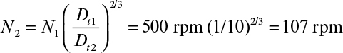
b. For constant tip speed to apply, NDt must be the same in both vessels:
c. For constant Reynolds number to apply, N![]() must be the same in both vessels:
must be the same in both vessels:

Example 10.4.†
† Adapted from J. Jost, Chapter 3 in S. L. Sandler and B. A. Finlayson, eds., Chemical Engineering Education in a Changing Environment, Engineering Foundation, New York, 1988.
As fermenters are scaled up, the mixing time usually increases. Mixing time, ![]() , can be defined as the time it takes for the concentration of a compound to return to 95% of the equilibrium value after a local perturbation in its concentration. Mixing times are experimentally determinable by step addition of an electrolyte. The conductivity can be measured continuously at various locations distant from the injection site.
, can be defined as the time it takes for the concentration of a compound to return to 95% of the equilibrium value after a local perturbation in its concentration. Mixing times are experimentally determinable by step addition of an electrolyte. The conductivity can be measured continuously at various locations distant from the injection site.

Figure 10.9. Schematic of a simple mixing model for Example 10.4. Ci = concentration of a component in the ith mixing compartment. (With permission, from J. L. Jost, in S. L. Sandler and B. A. Finlayson, eds., Chemical Engineering Education in a Changing Environment, Engineering Foundation, New York, 1980, pp. 21–36.)


a. Probe in the middle compartment:
a1. Small tank (10 l): F = 3.9 mg/l-s
C1 = 30.5 mg/1; C2 = 25 mg/1; C3 22.4 mg/1
a2. Large tank (10,000 l): F = 4.6 mg/l-s
C1 = 51.7 mg/1; C2 = 25 mg/1; C3 = 15 mg/1
b. Probe in the top compartment:
b1. Small tank (10 l): F = 3.2 mg/l-s
C1 = 25 mg/1; C2 = 20.5 mg/1; C3 = 18.4 mg/1
b2. Large tank (10,000 l): F = 2.2 mg/l-s
C1 = 25 mg/1; C2 = 12.1mg/1; C3 = 7.3mg/1
Over the last decade, increasing emphasis has been placed on the use of mini-scale (5 to 50 ml) or micro-scale (1 to 5 ml) bioreactors. While used largely for animal cells, the technology is applicable to all types of cells. A large number of parameters need to be explored to determine optimal conditions for cell growth and product formation. This is particularly true for therapeutic proteins where not only titer but also the “quality” of the protein product (e.g., extent of glycosylation) is critical. Miniaturized, scaled-down bioreactors are well suited for relatively high-throughput parallel operation, saving time, reducing costs of reagents and cells, and facilitating exploration of a larger experimental space than possible with traditional bioreactors. Coupling the output of such small-scale bioreactors to advanced analytical methods is a key aspect to successful use of such systems. A challenge, however, is to ensure that predictions from these mini bioreactors reflects the performance obtained in larger-scale systems.
Although microtiter plates and flasks can be used to screen culture conditions, for scale-up to large-scale reactors, it is best to use mini-scale stirred bioreactors or nonstirred suspension reactors that are membrane based. These bioreactors provide a more controlled environment than standard tissue culture flasks and allow estimation of transport parameters necessary for scale-up. The key parameters for scale-up to commercial-size vessels are kLa and mixing time. For animal cell culture, the maximum shear rate is also critical. Stirred-tank small-scale systems typically require more volume (10 to 35ml) than the membrane-based systems (0.5 to 3ml). Figure 10.10 is a schematic of a nonmechanically stirred membrane-based system. The system depicted depends on an oscillatory pressure wave as a motive force for fluid to move up and down in a U-tube. Published studies have shown, for several mini bioreactor systems, that it is feasible to scale up to pilot-size systems (e.g., 200 l) with good reproducibility.
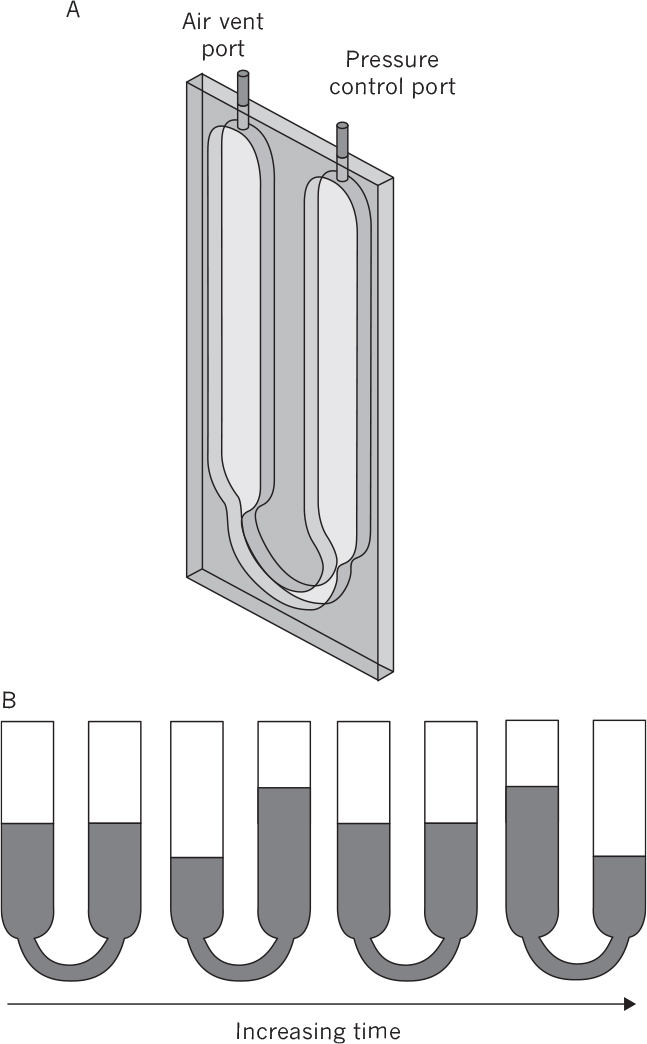
Figure 10.10. An example of a mini bioreactor with a selective membrane to facilitate O2 and CO2 transfer. Oscillatory air pressure causes fluid movement. (a) A schematic of the mini bioreactor holding 2.5 ml of fluid. Two 50 μm thick polymethylpenture membrane allow gas exchange while minimizing loss of water. (b) A typical fluid-mixing cycle and movement of liquid inside the channels. Fluid mixing is enhanced by fluid movement from the smaller bottom U-channel (5 mm wide) into the larger section of the system (12 mm wide). The kLa values can be readily calculated and dissolved oxygen levels directly measured. (From Kim, B. J., et al., Biotechnol. Bioeng. 109: 137, 2012, with permission from John Wiley & Sons, Inc.)
Although with modern techniques, a 1 ml reactor operated in fed-batch mode can supply sufficient volume for a range of analyses, stirred vessels of order of 10 ml provide more material for analytical procedures, particularly for automated cell analysis, without disturbing reactor performance. Instrumentation for monitoring the cell state as well as traditional parameters such or pH, DO, and cell mass is now available. Several vendors offer micro-scale systems with disposable microbioreactors and independent pH and DO control.
10.2. Bioreactor Instrumentation and Control
The maintenance of optimal conditions for product formation in the complex environment in a bioreactor requires the control and measurement of at least a few parameters. Almost all fermenters have pH, temperature, and DO control (by control of agitator rotational speed). New probes and techniques for the measurement of various ions, substrates, and products are being developed and have been implemented in particular situations. Actual process-control strategies for bioreactors are very primitive in comparison to the petrochemical industry because of a lack of sensors for on-line measurements and of reliable, quantitative, dynamically accurate models. In this section, we summarize briefly not only the state of the art but opportunities to improve the control of bioreactors.
10.2.1. Instrumentation for Measurements of Active Fermentation
The maintenance of sterility in a fermenter imposes a severe limitation on obtaining on-line measurements of fermentation parameters. Some probes (e.g., pH and dissolved oxygen) enter the reactor through penetrations in the fermenter shell. Each penetration significantly increases the probability of contamination. Thus, the benefit in increased productivity from the use of each probe must outweigh the economic losses that result from an increased number of contamination events. The probes themselves must also be sterilizable, preferably with steam. Thus, probes must ideally be able to withstand moderately high temperatures (121°C) in the presence of 100% humidity. Chemical sterilization, which is less desirable, may allow the use of a temperature-sensitive device if it has sufficient chemical resistance. Any general technique for monitoring fermentations must be compatible with the limitations imposed by sterility requirements.
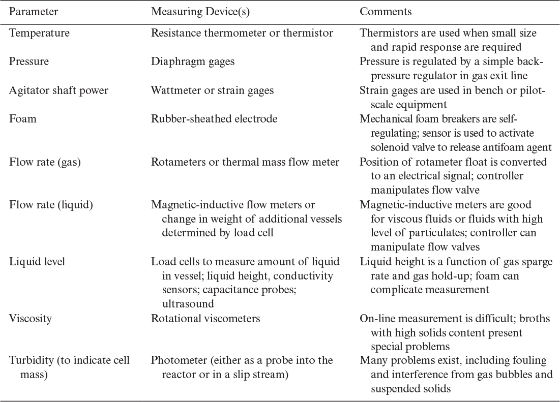
Techniques to monitor the physical environment are summarized in Table 10.5. Except for viscosity and turbidity, these parameters would be monitored on most pilot-plant fermenters and many industrial fermenters. Each parameter is generally subject to its own closed-loop control system. These individual control loops may be integrated into an overall control package, especially at the pilot-plant scale, but in many cases, higher-level control is not practiced, owing to the difficulty of measuring key parameters (e.g., product concentration) and the lack of dynamically accurate process models.
On-line measurements of concentrations beyond pH and DO are difficult, although exciting progress is being made. Table 10.6 summarizes techniques that have been considered for determining the concentrations of key components.
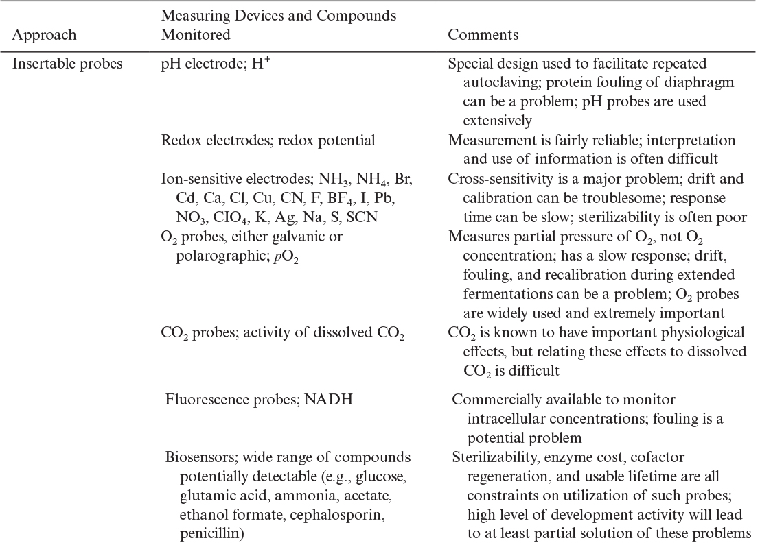

With insertable probes, we need to worry not only about probe performance but also about probe placement. The heterogeneity in a large fermenter means that DO and substrate levels (and to a lesser extent pH) will be position dependent (see Example 10.4). Although placement in the midsection of the vessel often gives the most representative values, mechanical design considerations may dictate placement elsewhere. Because probe fouling is a potential problem, the probe should be inserted in a region with sufficient turbulence to help keep it clean. Although the use of multiple probes would be desirable, the increased risk of contamination often argues against it. Even with accurate probe response, the interpretation of that response in a large fermenter must be done carefully.
Since many fermentations require extensive periods for completion (2 to 20 days), it is important that probe response be stable for extended periods. Industrial fermentation broths contain many proteins and other organics that have a significant tendency to adsorb onto surfaces. Many microbes also have a strong tendency to adhere to surfaces. Thus, probe fouling in an extended fermentation is a constant problem. Drift is a problem in some probes, and recalibration in situ is not always possible. If sterility is to be maintained, the removal and replacement of probes is practically impossible. In some cases, special designs allowing some back-flushing are possible. However, the quality of information available tends to decrease as the length of a fermentation cycle increases.
Exit-gas measurements, particularly with mass spectrometers, are of increasing interest. Advances in building robust process instruments at lower cost have made this a more attractive proposition, particularly when such an instrument can be used for several fermenters (e.g., using a computer-controlled switching manifold). The main limitation on exit-gas analysis is that only volatile components can be monitored.
On-line high-pressure liquid chromatography (HPLC) is very powerful for measuring the levels of dissolved solutes, particularly proteins made from genetically engineered cells. Many vendors are actively developing systems for this application. However, this method, as well as most others using a liquid slipstream, requires sample preparation and has a significant time delay associated with sampling. Typically, a small sidestream is pumped from the reactor, and microfiltration or an ultrafilter is used to remove cells and particulates. The filtrate usually requires further processing (e.g., the removal of compounds that could foul the analytical-grade columns). After injection of the sample, there can be a significant time (on order of minutes) before a response is obtained. One other problem with slipstreams is the potential for contamination; the membrane filtration step is of particular concern. Nonetheless, the use of liquid slipstreams allows the relatively rapid determination of important product information. The use of HPLC is most common on laboratory- or pilot-scale systems.
Other methods not listed in Table 10.6 have the potential to significantly affect the on-line measurement of fermentation parameters. Nuclear magnetic resonance (NMR) has given important information on intracellular metabolism for off-line or small-scale growth experiments. In situ NMR has the potential for use with at least bench-scale systems, although significant technical advances must first be made. Selective fluorescence in combination with flow cytometry has given important information, off line, on the distribution of intracellular parameters (e.g., plasmid content) in a population. The adaptation of such techniques to on-line measurement is conceivable, but again, a number of technical problems must first be solved. Another analytical method that offers a good potential for on-line determination of solutes is Fourier transform infrared (FTIR) spectra analysis. Raman spectroscopy is being used with animal cell culture, enabling noninvasive analysis of cellular metabolic changes. Finally, the use of spectra analysis combined with optical fibers may offer a good technique to determine cell mass in the presence of other suspended solids.
10.2.2. Using the Information Obtained
Having information is one thing; using it wisely is another. Current fermenter design and control techniques are rather limited. We do not have a fully satisfactory approach to the effective use of information on the extracellular and intracellular chemical environments.
Computer-controlled fermenters are fairly common, particularly at the pilot-plant scale. Figure 10.11 displays an overview of the software functions for a typical antibiotic fermentation facility, and Figure 10.12 shows the relationship of primary measurements to secondary parameters.
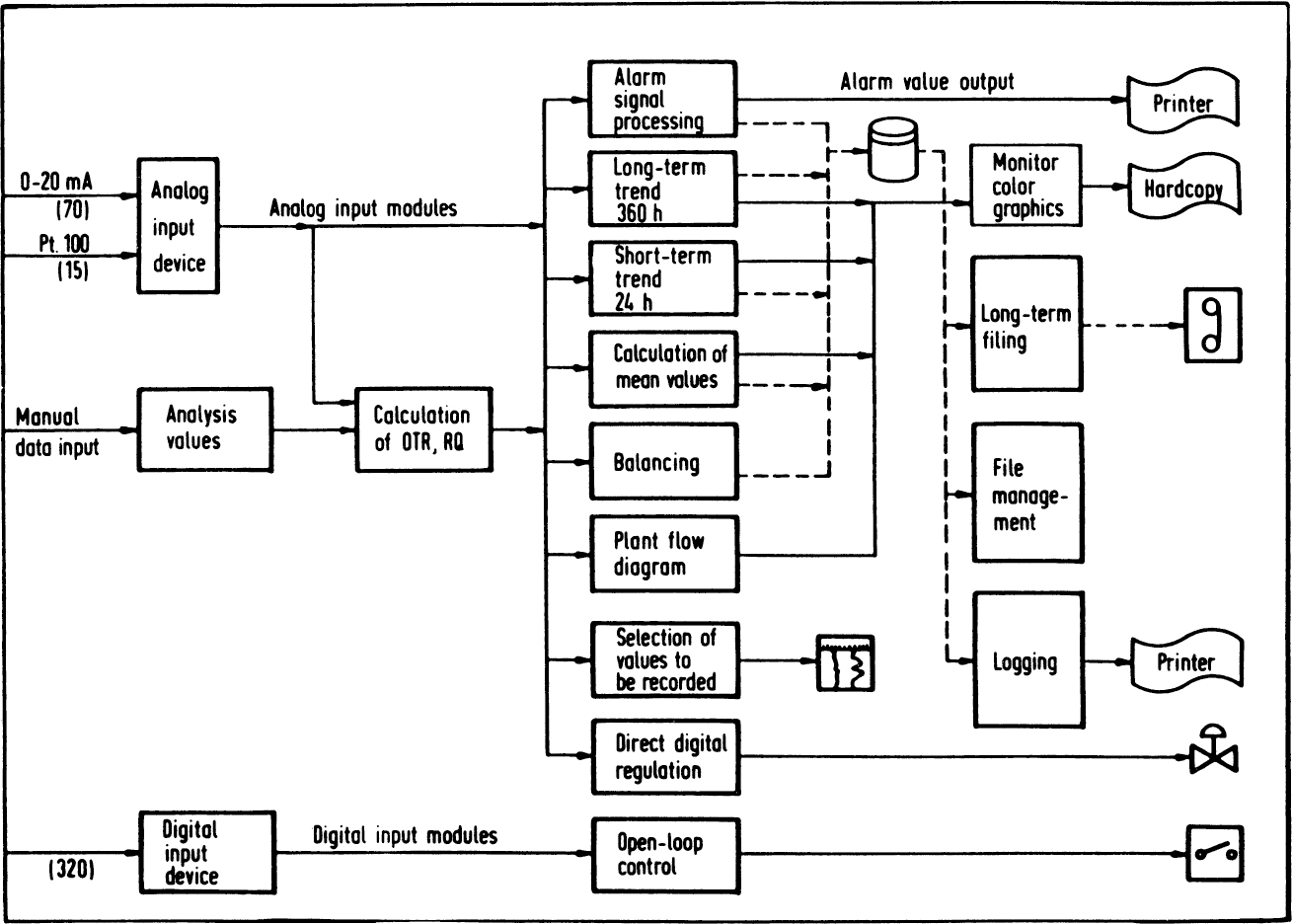
Figure 10.11. Overview of software for fermentation. (With permission, from H. Heine, J. Hahn, and A. Mangold, in Biotechnology Focus I, R. K. Finn and P. Prave, eds., Hanser Publishers, New York, 1988, p. 203.)
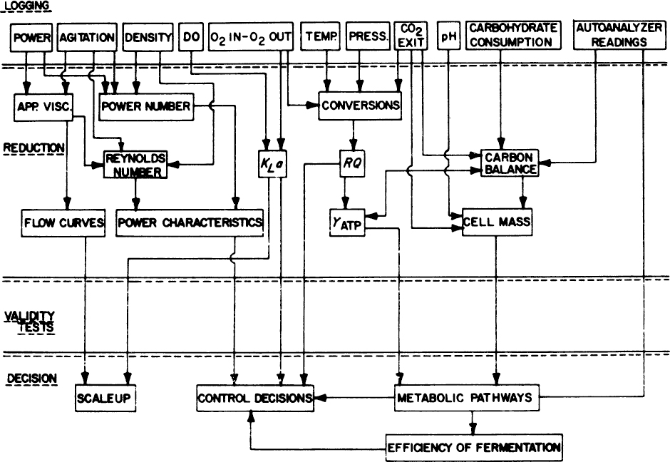
Figure 10.12. Primary measurements, shown on top, may be used to calculate many related process properties and parameters. (With permission, from L. P. Tannen and L. K. Nyiri, “Instrumentation of Fermentation Systems,” p. 331, in Microbial Technology, 2d ed., Vol. II, H. J. Peppler and D. Perlman, eds., Academic Press, New York, 1979.)
An important function of such systems is data logging. This information is unusually important in the food and pharmaceutical industries. An actual record for the manufacture of each product batch is required by regulatory agencies. If the product is later found to be unsafe, such information can be used to trace the problem. Beyond the regulatory concerns, the lack of good high-level control strategies leads to a control strategy based on exactly duplicating a particular recipe. Consistency from batch to batch is an important consideration. Expert control systems may be useful in such situations.
In many cases, fermentation control schemes have begun to move beyond simple open-loop environmental control strategies. The use of computers allows the rapid manipulation of information from the data-logging operation to yield estimates of secondary parameters. For example, a secondary parameter may be cell concentration estimated from estimates of oxygen consumption or carbon dioxide evolution based on primary measurements of off-gas composition and dissolved-gas concentrations. Essentially, cell mass is estimated from mass balances using information from what have been termed gateway sensors. The main limitation to this approach is the accumulation of error. For example, in estimating cell mass X at time t, the value of X at time t – Δt must be known. Any systematic errors in cell mass estimates or the inability of an algorithm to respond to an unusual perturbation can lead to significant difficulties over the length of a typical culture cycle. Data-handling procedures to mitigate this problem have been suggested (e.g., Kalman filters).
In some cases, our partial knowledge of cellular metabolism is sufficient to solve important bioreactor problems. For many years, it was thought impossible to grow E. coli to high cell densities (>15 or 20 g/l). An improved understanding of cell physiology led to the observation that it was the buildup of toxic metabolic by-products (primarily acetate) that inhibited growth. Acetate is formed in E. coli when a good carbon source, such as glucose, is available in high concentrations. Control strategies that feed glucose at a rate sufficient to maintain at least moderately good growth without forming acetate were seen as possibilities to improve reactor volumetric productivities.
Thus, several possible control strategies are immediately apparent. The simplest perhaps would be to measure acetate concentration on line and reduce nutrient feed rates in response to acetate accumulation. On-line measurement of acetate is not now routine, but improvements in sensors certainly make this a tenable approach. A strategy that is easier to implement with current sensors is based on measuring the rates of CO2 evolution. Measurement of CO2 in the off-gas, coupled with information on substrate concentration in the feed and nutrient flow rates, allows the glucose feed rate to be manipulated to maintain glucose concentrations at an optimal level. This indirect strategy depends on the use of mass balances and the gateway sensor concept. Another strategy is to control glucose concentration with a feedback control system if a glucose sensing system is available. The easiest approach is to use a predetermined glucose feeding schedule, although this usually results in significant periods of suboptimal or superoptimal glucose concentrations. These strategies have been used successfully. High-density E. coli cultures (ca. 100 g dry wt/l) have greatly increased product concentration and productivities in E. coli-based fermentations to make proteins from recombinant DNA. At these high densities, special strategies for oxygen supply (e.g., O2-enriched gas) are often required. This example illustrates the important interaction between process-control strategies and cellular metabolism.
As we develop better sensors and a better understanding of metabolic pathways, it becomes more feasible to combine information from primary sensors with models of metabolism to develop better control strategies. Without direct measurement of the product, simple feedback control on the process itself is impossible. Without extremely good models for dynamic response, feedforward control strategies are ineffective. Because of the highly nonlinear nature of most culture systems, black-box techniques to develop dynamic models are usually ineffective. Good process control for fermentations awaits improved models of cultures, more sophisticated sensors, and advances in nonlinear control theory. Hierarchical bioprocess automation where control is based on interconnecting parameters is now feasible. Such an approach requires relating typical process parameters (e.g., pH, DO, nutrient concentrations, cell concentration) to quality attributes (e.g., protein folding, glycosylation patterns of proteins, impurities). Currently, semiempirical models to relate process parameters to quality attributes are possible but are not routine and are not easily utilizable.
In addition to reactor control, a computer-monitored and controlled process involves the control of medium preparation, sterilization, and some downstream recovery processes. An important factor in bioprocesses is the predominance of batch processing. The scheduling of equipment is critical, and these tasks are being done increasingly with the aid of in-house computers.
10.3. Sterilization of Process Fluids
Modern fermenters consume large amounts of media and gas. The tens of thousands of liters of medium and millions of liters of air used in a typical antibiotic fermentation must be absolutely devoid of any contaminating organism. The economic penalty for contamination is high. With bioprocesses to make proteins from recombinant DNA, the exit streams must also be treated to prevent the discharge of any living cell. The ability to ensure the destruction of viable organisms is critical.
10.3.1. The Kinetics of Death
Sterility is an absolute concept; a system is never partially or almost sterile. However, with a 100,000 l fermenter, we cannot sample every drop of fluid for a foreign organism. On a practical basis, sterility means the absence of any detectable viable organism, and a pure culture means that only the desired organism is detectably present.
Disinfection differs from sterilization. A disinfecting agent will greatly reduce the number of viable organisms, often a specific type of organism, to a low but nonzero value.
Fluid streams can be sterilized through the physical removal of cells and viruses or the inactivation of living particles by heat, radiation, or chemicals. If sterilization is accomplished by inactivating living cells, spores, or viruses, we need to understand the kinetics of death. Death in this case means the failure of the cell, spore, or virus to reproduce or germinate when placed in a favorable environment. When dealing with sterilization, the probabilistic nature of cell death cannot be ignored.
The simplest case presumes that all the viable cells or spores are identical. The probability of extinction of the total population, P0(t), follows:
Here p(t) is the probability that an individual will still be viable at time t, and N0 is the number of individuals initially present. The expected number of individuals present at time t, E[N(t)], is as follows:
The variance about this number is
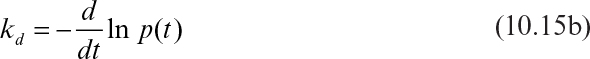
The specific death rate, kd, is

And if p(t) is not a function of N(t), then
The functional form for p(t) depends on the organism and environment. The simplest form is to assume a first-order death model in which kd is a constant and has units of reciprocal time:
In the microbiological literature, the term decimal reduction time (D) is often used. It is the time for the number of viable cells to decrease tenfold. For example, with kd as a constant, the value of D is
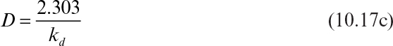
A plot of ln N(t)/N0 versus time is called a survival curve (see Figure 10.13). Such a curve is implicitly deterministic; the deterministic and probabilistic approaches give essentially the same result as long as N(t) is >>1 (about 10 to 100). Extrapolation of a survival curve to one organism or less is not proper.
Figure 10.13. (a) Typical death-rate data for spores of Bacillus stearothermophilus Fs 7954 in distilled water, where N = number of viable spores at any time, N0 = original number of viable spores. (b) Typical death rate for E. coli in buffer, where N = number of viable cells at any time and N0 = original number of viable cells. (With permission, from S. Aiba, A. E. Humphrey, and N. F. Millis, Biochemical Engineering, 2d ed., University of Tokyo Press, Tokyo, 1973, p. 241.)
Most real populations are not homogenous. Often, a subgroup is more resistant to the sterilization agent. Also, organisms growing in clumps tend to be more resistant to death. These factors are important in processing (see Figure 10.14 for the effects on survival curves). For example, consider a tragic error in the early development of a polio vaccine. The virus is inactivated (“killed”). The required processing time was estimated from linear extrapolation (on a semilog plot) of a survival curve. The original data for the plot did not extend to sufficiently low numbers to detect the presence of a resistant subpopulation. Consequently, some patients were inoculated with live rather than killed virus.
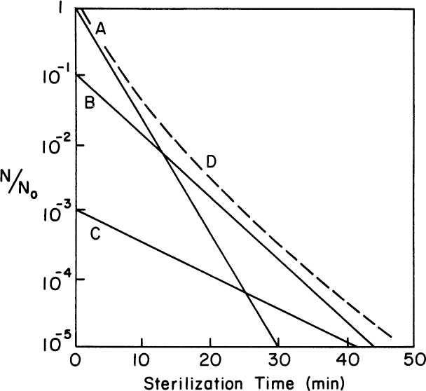
Figure 10.14. Overall survival curve (D) for a system with three distinct subpopulations (A, B, and C). Population A is normally dominant, but it is the one most sensitive to the sterilizing agent, while subpopulation C is far more resistant.
10.3.2. Sterilization of Liquids
The kinetics of death apply to the sterilization of liquids. Values for kd can be determined for inactivation by chemical, thermal, or radioactive agents. Thermal inactivation is very much preferred for the economic, large-scale sterilization of equipment and liquids. However, heat-sensitive equipment must be sterilized with chemical agents or radiation.
The use of ultraviolet (UV) radiation is effective to sterilize surfaces, but UV cannot penetrate fluids easily, particularly those with high amounts of suspended material. Although x-rays can penetrate more deeply, cost and safety considerations preclude their use in large-scale systems.
A chemical agent for sterilization must leave no residue that would be toxic to the desired culture. Ethylene oxide, a gas, can be used to sterilize equipment. A 70% ethanol–water mixture acidified to a pH of 2 with HCl kills virtually all vegetative cells and many spores and can be used to sterilize equipment. A formaldehyde solution is often effective. Sodium hypochlorite solution (3%) has been used in sterilizing (or disinfecting) small-scale, heat-sensitive equipment. Some chemicals (e.g., ozone) cannot usually be used to sterilize fluids without adverse side reactions affecting medium quality.
For most large-scale equipment and liquids, thermal sterilization is used (filter sterilization is the only practical alternative for liquids). Usually, the dependence of the specific death rate on temperature is given by an Arrhenius equation:
where R is the gas constant, T is absolute temperature, and E0d is the activation energy for the death of the organism. Values for E0d range from about 50 to 150 kcal/g-mol. For spores of Bacillus stearothermophilus, E0d ≈ 70 kcal/g-mol, and values of 127 kcal/g-mol have been determined for E. coli. Most thermal sterilizations take place at 121°C. The values for kd in such situations are very high for vegetative cells (often >1010 min–1). For spores, the values of kd typically range from 0.5 to 5.0 min–1. In most cases, we are only concerned about spores when steam-sterilizing equipment and media, since the value of kd is so much lower with spores than vegetative cells.
The E0d for vitamins and growth factors in many media is about 2 to 20 kcal/g-mol. The inactivation of viability is much more sensitive to temperature changes than the degradation of important growth factors in the medium. This factor is important to the design of sterilization equipment and protocols so as to assure complete killing of foreign organisms without the destruction of necessary growth factors in the medium.
The main factors in any sterilization protocol are the temperature, time of exposure, and initial number of organisms that must be killed. The problems of sterilization increase with scale-up. Consider the probability of an unsuccessful fermentation, [1 - P0(t)], in a reactor:
or with a simple model of killing in homogeneous populations:
N0 in equation 10.19 corresponds to the number of individuals in the reactor, not the concentration of organisms. Let n0 be the concentration of particles. Now consider the probability of an unsuccessful sterilization in a 1 l and a 10,000 l reactor, where each contains the identical solution (n0is the same in both tanks), and the temperature (kd) and time of sterilization are identical. Thus, for the 1 l tank,
And for the 10,000 l tank,
If kdt is 15 and n0 = 104 spores/l in both cases, the probability of an unsuccessful fermentation is 0.003 in the 1 l vessel and about 1 in the 10,000 l tank (5 · 10-14 probability of extinction of the spores). Thus, the sterilization protocol that would be acceptable for a laboratory bench-scale experiment would be totally unacceptable for the larger-scale system. The larger tank would require much longer exposure to the same temperature to achieve the same degree of sterility, and the longer exposure to higher temperatures could lead to greater changes in the chemical composition of the medium.
A sterilization chart can be constructed from equation 10.19b. An example is depicted in Figure 10.15. To use such a chart, you need to specify the probability of failure that is acceptable (e.g., 10-3) and the number of particles initially present in the fluid (n0 total volume). For 10-3 and N0 = 108, the corresponding value of kdt is about 26. If kd = 1 min–1 at 121°C, then t = 26 min corresponds to the exposure time at 121°C required to ensure that 999 out of 1000 sterilizations are successful.
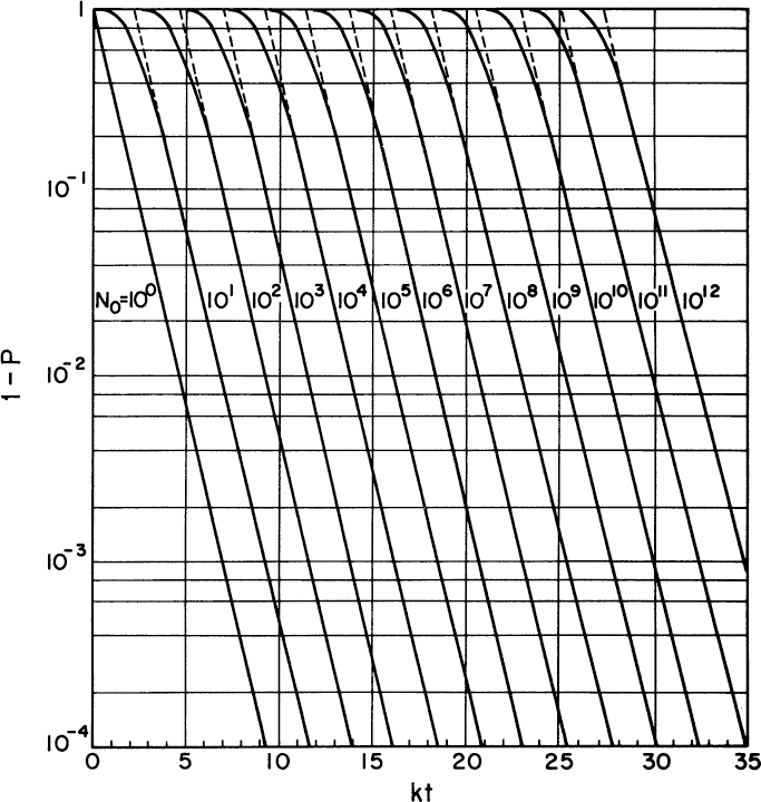
Figure 10.15. Sterilization chart. (With permission, from M. L. Shuler, Encyclopedia of Physical Science and Technology, Vol. 2, p. 427, Academic Press, New York, 1987.)
Steam sterilizations can be accomplished batchwise, often in situ in the fermentation vessel, or in a continuous apparatus (Figure 10.16). The greatest difficulty with batch sterilization is thermal lags and incomplete mixing. Typically, batch sterilization occurs at 121°C. The time required to heat the fluid to 121°C and to cool it back to growth temperatures (e.g., 37°C) is often much longer than the time of exposure to the desired temperature. For most spores, kd falls very rapidly with temperatures (e.g., a tenfold decrease for kd at T = 110°C rather than 121°C), so the heat-up and cool-down periods do little to augment spore killing. However, the elevated temperatures during heat-up and cool-down can be very damaging to vitamins and proteins, can lead to caramelization reactions for sugars, and can greatly alter medium quality.
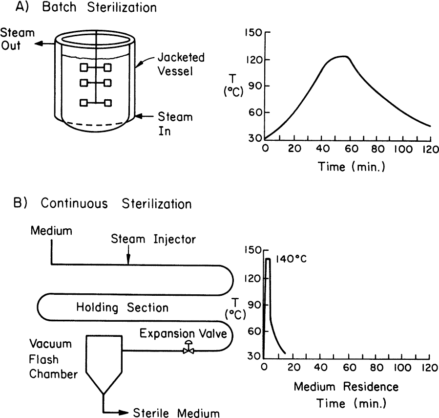
Figure 10.16. Comparison of a batch (a) with a continuous sterilization strategy (b) for the temperature profile of the medium sterilized. The continuous unit allows short-time, high-temperature sterilization.
Continuous sterilization, particularly a high-temperature, short-exposure time, can achieve complete sterilization with much less damage to the medium. Both the heat-up and cool-down periods are very rapid. Continuous sterilization is easier to control and reduces downtime in the fermenters. Two potential disadvantages of the continuous process are dilution of the medium with steam injection and foaming. The flow pattern inside the pipe is critical, since the fluid residence time near the wall can be different from that in the center. The average flow rate and the length of the sterilizing section should be designed to ensure high Peclet numbers (above 500), so that the velocity distribution approaches piston-like flow.
In addition to steam sterilization, process fluids can be filter sterilized. Filter sterilization is necessary when the medium contains heat-sensitive materials. An important example of filter sterilization in bioprocesses is the sterilization of medium to support the growth of animal cells. Microporous filters (pore sizes <0.2 μm) are typically used. The filters should be absolute filters; no pores larger than the nominal pore size must exist. A very narrow pore-size distribution is advantageous. The medium may be first prefiltered to remove large particulates that might plug the microporous filter. The actual microporous filter must be sterilized. The equipment that receives the filtered–sterilized fluid is also sterilized.
Filter sterilization is not as reliable as steam sterilization. Any defect in the membrane can lead to failure. Viruses and mycoplasma (small wall-less bacteria) can pass the filter. Consequently, filtered–sterilized medium is usually quarantined for a period of time to allow any contaminants to multiply to a detectable number. Clearly, a period of quarantine will detect only vegetative cells and not host-dependent contaminants (e.g., viruses).
Filter sterilization is used not only to filter medium but also to sterilize process air.
10.3.3. Sterilization of Gases
Aerobic fermentations require huge volumes of air. At 0.1 to 1 volume of gas per volume of liquid per minute, a 50,000 l fermenter requires 7 · 106 l to 7 · 107 l per day of air. Many fermentations are several days in duration. For a five-day fermentation, as much as 2 · 108 l of air may be required. This volume of air must be absolutely sterile. Typically, the concentration of microbes in air is 103 to 104/m3 or 1 to 10 microbes/l. Fed-batch or continuous culture systems place even more stringent demands on air sterilization, since air filters cannot be replaced during the run period.
An air supply of this magnitude requires sizable air compressors. Adiabatic compression of air can increase the air temperature (typically 150° to 220°C). Dry heat is less effective than moist heat in killing organisms. To kill spores, a temperature typically of 220°C for 30 s is required. Consequently, the adiabatic compression of process air certainly aids air sterilization. Since the exit air cools rapidly and the pipes connecting the compressor to the fermenter are difficult to maintain as absolutely sterile, an air-filtration step is almost always used. (Alternatives such as UV radiation, ozone injection, and scrubbing are not practical.)
The filtration of gases can be accomplished using either depth filters or surface filters. Historically, depth filters using glass wool were used, but depth filters have been almost totally replaced with membrane cartridge filters, which are surface filters.
Glass wool filters rely on a combination of mechanisms for the capture of particles. Possible mechanisms of removal for particles of about 1 μm diameter are direct interception, electrostatic effects, diffusion (or Brownian motion), and inertial effects. As the flowing gas approaches a fiber, the flow streamlines must curve around the fiber. If a particle had no density, it would follow the streamlines around the fiber. Only particles whose centers are on streamlines less than a particle radius away from the fiber could be intercepted. However, for real particles, inertial effects mean that particles with mass will have a tendency to maintain a straight-line trajectory as they approach the fiber. Thus, such particles deviate from the streamline and crash into the fiber. Both interception and inertial effects are important in removing bacteria.
Diffusional effects may be important for virus removal, but bacteria are sufficiently large that diffusion is relatively unimportant. The removal of a particle by these mechanisms is probabilistic. The deeper the filter is, the smaller the probability of a particle penetrating the depth of the filter.
Depth filters using glass wool can show shrinkage and hardening upon steam sterilization. In such cases, channeling can occur, and the filter becomes far less effective than would be predicted. More recent advances in the design of fiberglass filter cartridges have overcome much of this disadvantage. Another serious problem with such fibrous filters is wetting. If a filter wets, an easy path becomes available for a contaminant to penetrate through it. A wet filter also greatly increases pressure drop. Thus, any condensation within such a filter must be avoided.
Surface filters (membrane cartridges) work using another mechanism for particle removal, a sieving effect. Figure 10.17 depicts a membrane cartridge unit and its housing. Membranes with uniformly small pores prevent the passage of particles with a radius larger than the pore radius. Such filters can be steam-sterilized many times. Also, any condensate formed on the nonsterile side cannot pass into the sterile side.

Figure 10.17. (a) A Pull-Emflon membrane cartridge for filter sterilization of air. (b) Housing for air sterilization filter. (With permission, from W. Crueger, “Sterile Techniques in Biotechnology,” in R. K. Finn and P. Prave, eds., Biotechnology Focus 2, Hanser Publishers, New York, 1990, p. 413.)
With both depth filters and membrane cartridges, pressure drop is critical. The energy input for compressed air for a commercial-scale process is significant. Air treatment can account for 25% of total production costs. Thus, the design engineer has to balance the assurance of sterility against pressure drop.
Generally, the bioprocess engineer is not involved in the design of membrane cartridge units (a number of competent vendors offer suitable products), but the testing of such units for effectiveness is important. In the United States, an example is an aerosol test using corn oil nebulized to 1.0 to 1.5 mg oil/l of air. This test is recognized by the FDA. Such an aerosol would contain particles primarily in the range of 0.2 to 1.0 μm in diameter. Aerosol in the exit gas from a filter cartridge can be monitored by a photometer. The number of sterilization cycles a cartridge can undergo before failure is an important criterion in the selection of membrane cartridge units.
Other tests for the integrity of the unit are pressure-drop-versus-flow-rate and bubble-point tests, which detect defects in the membrane and maximum pore size. Grow-through tests use a sterile nutrient solution on one side of the membrane and a similar nutrient solution inoculated with a test strain (e.g., Pseudomonas diminuta) on the nonsterile side. The greater the integrity of the filter, the longer it will take before growth on the nominally sterile side will occur. A filter should be evaluated with several different types of tests.
Because of the high costs associated with the loss of a batch due to contamination, the choice of air filter to give dependable protection for a fermentation while minimizing pressure drop is critical.
So far, we have considered only inlet gas streams. With fermentations involving pathogens (disease-causing organisms) or recombinant DNA, all organisms must be removed from the exhaust gas. The concentration of microbes in the exit gas is far higher than in the inlet gas. Catalytically aided combustion (incineration) of the exit gas is an effective, but expensive, solution. Consequently, filtration of the exit air is of increasing importance.
10.4. Summary
Scale-up of reactors is a task primarily for the bioprocess engineer. Three basic reactor types for the aerobic cultivation of suspended cells are mechanically agitated reactors, bubble columns, and loop reactors. Although the bubble and loop reactors offer advantages in terms of energy efficiency and reduced shear damage to cells, the traditional stirred-tank system is more flexible and can better handle broths that become highly viscous.
The primary limitations on the size of stirred-tank bioreactors are gas supply (e.g., O2) and heat removal. The value of KLa, of the volumetric transfer coefficient, is of prime concern. Its value depends not only on the equipment used, gas flow rates, and agitator speed, but also on the nature of the fluid (salt content, presence of surface active agents, and viscosity). The properties of the fluid can change during the fermentation. By directly monitoring oxygen concentration in the gas phase and the dissolved-oxygen level, it is possible to make on-line estimates of KLa. If the rate of oxygen uptake is known, the rate of heat generation can be readily estimated in aerobic fermentations.
Scale-up is difficult, because conditions in a large vessel are much more heterogeneous than in a small vessel. If geometrically similar tanks are used, it is impossible to maintain identical values of shear, mixing times, and kLa simultaneously in both the large and small tanks. Scale-up would be simplified if good reaction models could be coupled to good transport models; since this is not yet possible, scale-down techniques are a good alternative.
Bioreactor instrumentation and control are less advanced than in the petrochemical industry. Improvements in sensor technology and the dynamical models of bioreactors are critical to improvements in control technology.
The large-scale bioreactor places heavy demands on processes to sterilize (kill or remove all organisms from) fluids entering the bioreactor. Liquid streams are thermally sterilized or filter sterilized. Steam sterilization is preferred, but the sterilization process must not damage the ability of the medium to support growth. Since longer periods of exposure to high temperatures are necessary to assure sterility in larger volumes of liquid, the sterilization process can alter the medium composition more for large-scale than for small-scale systems. This is an additional factor that can lead to differences in productivity upon scale-up. Continuous sterilization protects the medium components from degradation better than batch sterilization, because the heat-up and cool-down periods are greatly minimized. Filter sterilization of liquids is used when the medium contains particularly heat-sensitive components. Air streams are typically filter sterilized. Surface filters (membrane cartridges) are commonly used in gas sterilization.
Suggestions for Further Reading
General References
BAILEY, J. E., AND D. F. OLLIS, Biochemical Engineering Fundamentals, 2d ed., McGraw-Hill, New York, 1986.
BLANCH, H. W., AND D. S. CLARK, Biochemical Engineering, Marcel Dekker, New York, 1996.
DORAN, P. M., Bioprocess Engineering Principles, 2d ed., Academic Press, San Diego, 2013.
Specific Articles and Books
ALFORD, J. S., “Bioprocess Control: Advances and Challenges,” Comput. Chem. Eng. 30: 1464–1475, 2006.
AMANULLAH, A., J. M. OTERRO, M. MIKOLA, A. HSU, J. ZHANG, J. AUNINS, H. B. SCHREYER, J. A. HOPE, AND A. P. RUSSO, “Novel Micro-Bioreactor High Throughput Technology for Cell Culture Process Development: Reproducibility and Scalability Assessment of Fed-Batch CHO Cultures,” Biotechnol. Bioeng. 106: 57–67, 2010.
BULL, D. N., R. W. THOMA, AND T. E. STINNETT, “Bioreactors for Submerged Culture,” Adv. Biotechnol. Processes 1: 1–30, 1983.
BYLUND, F., F. GUILLARD, S.-O. ENFORS, C. TRäGARDH, AND G. LARSSON, “Scale Down of Recombinant Protein Production: A Comparative Study of Scaling Performance,” Bioprocess Eng. 20: 327–389, 1999.
GARCIA-OCHEA, F., AND E. GOMEZ, “Bioreactor Scale Up and Oxygen Transfer Rate in Microbial Processes: An Overview,” Biotechnology Advances 27: 153–176, 2009.
JOST, J., “Selected Bioengineering Problems in Stirred-Tank Fermenters,” in S. L. Sandler and B. A. Finlayson, eds., Chemical Engineering Education in a Changing Environment, Engineering Foundation, New York, 1988.
JUNKER, B. H., M. STANIK, C. BARNA, P. SALMON, E. PAUL, AND B. C. BUCKLAND, “Influence of Impeller Type on Power Input in Fermentation Vessels,” Bioprocess Eng. 18: 401–412, 1998.
KARGI, F., AND M. MOO-YOUNG, “Transport Phenomena in Bioprocesses,” in Comprehensive Biotechnology, Vol. 2, M. Moo-Young, ed., Pergamon Press, Oxford, UK, 1985, pp. 5–55.
KIM, B. J., J. DIAO, AND M. L. SHULER, “Mini-scale Bioprocessing Systems for Highly Parallel Animal Cell Cultures,” Biotechnol. Progr. 28: 595–607, 2012.
KLUTZ, S., J. MAGNUS, M. LOBEDANN, P. SCHAWN, B. MAISER, J. NIKLAS, M. TEMMING, AND G. SCHEMBECKER, “Developing the Biofacility of the Future Based on Continuous Processing and Single-Use Technology,” J. Biotechnol. 213: 120–130, 2015.
KOMIVES, C., AND R. S. PARKER, “Bioreactor State Estimation and Control,” Curr. Opin. Biotechnol. 14: 468–474, 2003.
LOFFELHOLZ, C., S. C. KAISER, M. KRAUME, R. EIBL, AND D. EIBL, “Dynamic Single-use Bioreactors Used in Modern Liter and m3-scale Biotechnological Processes: Engineering Characteristics and Scaling Up,” Adv. Biochem. Eng./Biotechnol. 138: 1–44, 2014.
POHLSCHEIDT, M., S. CHARANIYA, C. BORK, M. JENZSCH, T. NOETZEL, AND A. LUEBBERT, “Bioprocess and Fermentation Monitoring,” Chapter 69, pp. 1471–1491, in Upstream Industrial Biotechnology: Equipment, Process Design, Sensing, Control, and cGMP Operations, Vol. 2, M. C. Flickenger, ed., 2013.
RAMEEZ, S., S. S. MOSTAFA, C. MILLER, AND A. SHUKLA, “High-Throughput Miniaturized Bioreactors for Cell Culture Process Development; Reproducibility, Scalability and Control,” Biotechnol. Progr. 30: 718–727, 2014.
Problems
10.1. The air supply to a fermenter was turned off for a short period of time and then restarted. A value for C* of 7.3 mg/l of has been determined for the operating conditions. Use the tabulated measurements of dissolved oxygen (DO) values in the following table to estimate the oxygen uptake rate and kLa in this system.
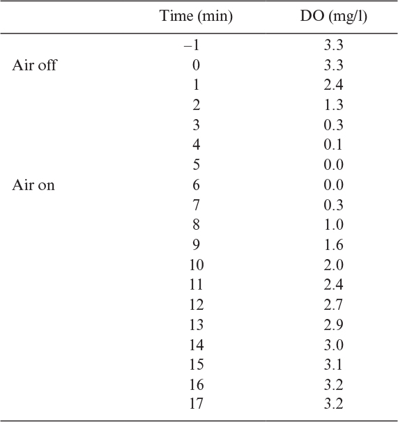
10.2. A value of kLa = 30 h-1 has been determined for a fermenter at its maximum practical agitator rotational speed and with air being sparged at 0.5 l gas/l reactor volume-min. E. coli with a qo2 of 10 mmol O2/g-dry wt-h are to be cultured. The critical dissolved oxygen concentration is 0.2 mg/l. The solubility of oxygen from air in the fermentation broth is 7.3 mg/l at 30°C.
a. What maximum concentration of E. coli can be sustained in this fermenter under aerobic conditions?
b. What concentration could be maintained if pure oxygen was used to sparge the reactor?
10.3. You are asked to design the temperature control system for a large fermenter.
a. Estimate the required cooling-water flow rate for a 100,000 l fermenter with an 80,000 l working volume when the rate of oxygen consumption is 100 mmol O2/1-h. The desired operating temperature is 35°C. A cooling coil is to be used. The minimum allowable temperature differential between the cooling water and the broth is 5°C. Cooling water is available at 15°C. The heat capacities of the broth and the cooling water are roughly equal.
b. Estimate the required length of cooling coil if the coil has a 2.5-cm diameter and the overall heat transfer coefficient is 1420 J/s-m2-°C.
10.4. A lethal agent (KCN) was added to the fermentation medium in the presence of aeration using diffusors. Dissolved oxygen (DO) concentration increased with time as follows when N = 100 rev/min:
Saturation DO concentration in the fermentation medium is 7.0 mg/L.
a. Determine oxygen transfer coefficient kLa.
b. Determine kLa when Ni is increased to 200 rev/min.
10.5. A laboratory-scale stirred-tank fermenter of volume 5 l (Do/H = 1/2) is to be scaled up to 500 l by using the following criteria: Di/Do = 1/3, N = 100 rev/min. Determine the size of the fermenter, impeller diameter and speed for each case:
a. Constant oxygen transfer rate
b. Constant power/volume
c. Constant impeller tip speed
d. Constant mixing time
10.6. Consider Example 10.4. What would be the substrate concentrations in each compartment in the 10 l and 10,000 l tanks if the probe were placed in the bottom compartment?
10.7. Consider the 10 l and 10,000 l tanks described in Example 10.4. Suppose that fully continuous operation is to be used, F was fixed at 5 mg/l-s for both tanks, and D = 0.2 h-1 for each tank with fluid removal from the top. What fraction of the inlet substrate would be consumed in each tank? If the biomass yield coefficient were 0.5 g cells/g substrate and YP/X = 0.1 g product/g cells, what would be the effect on volumetric productivity upon scale-up?
10.8. A continuous culture system is being constructed. The fermentation tank is to be 50,000 l in size, and the residence time is to be 2 h. A continuous sterilizer is to be used. The unsterilized medium contains 104spores/l. The value of kd has been determined to be 1 min-1 at 121°C and 61 min-1 at 140°C. For each temperature (121°C and 140°C), determine the required residence time in the holding section so as to ensure that 99% of the time 4 weeks of continuous operation can be obtained without contamination (due to contaminants in the liquid medium).
10.9. Discuss the effects of mixing on sterilization in a batch fermenter.
10.10. A medium containing a vitamin is to be sterilized. Assume that the number of spores initially present is 105/l. The values of the pre-Arrhenius constant and E0d for the spores are
E0d = 65 kcal/g-mol
α = 1·1036min-1
For the inactivation of the vitamin, the values of E0d and α are
E0d = 10 kcal/g-mol
a = 1 · 104min-1
The initial concentration of the vitamin is 30 mg/l. Compare the amount of active vitamin in the sterilized medium for 10 l and 10,000 l fermenters when both are sterilized at 121°C when we require in both cases that the probability of an unsuccessful fermentation be 0.001. Ignore the effects of the heat-up and cool-down periods.
10.11. Consider the data given in the following table on the temperature changes in a 10,000 l fermenter, which includes the heat-up and cool-down periods. Use the values for the Arrhenius parameters given in Problem 10.8 and assume an initial spore concentration of 105/l and a vitamin concentration of 30 mg/l.

a. What is the probability of a successful sterilization?
b. What fraction of the vitamin remains undegraded?
c. What fraction of the vitamin is degraded in the sterilization period?
d. What fraction of the vitamin is degraded in the heat-up and cool-down periods?
e. What is the fraction of spores deactivated in the heat-up and cool-down cycles?
10.12. E. coli has a maximum respiration rate, qo2max, of about 240 mg O2/g-dry wt-h. It is desired to achieve a cell mass of 20 g dry wt/l. The kLa is in a 1000 l reactor (800 l working volume). A gas stream enriched in oxygen is used (i.e., 80% O2), which gives a value of c* = 28 mg/L. If oxygen becomes limiting, growth and respiration slow; following is an example:
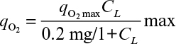
Here CL is the dissolved oxygen concentration in the fermenter. What is CL when the cell mass is at 20 g/l?
10.13. The temperature history of the heating and cooling of a 40,000 l tank during sterilization of medium follows: 0 to 15 min, T = 85°C; 15 to 40 min, T = 121°C; 40 to 50 min, T = 85°C; 50 to 60 min, T = 55°C;> 60 min, T = 30°C. The medium contains vitamins, the most fragile of the vitamins has an activation energy for destruction of 10 kcal/g-mol and the value of α (see equation 10.18) is 1 · 104 min–1. Assume vitamin destruction is first order and the initial concentration is 50 mg/1. R is 1.99 cal/g-mol-K. The medium contains 2.5·103 spores/l. The spores have an E0d = 65 kcal/g-mol, and kd at 121°C is 1.02 min-1. Estimate the probability of a successful sterilization. What fraction of the vitamin remains active?
10.14. Estimate kLa from Figure 10.5 if C* is 35 mg/l due to the use of nearly pure oxygen rather than air.
10.15. In cultivation of baker’s yeast in a stirred and aerated tank, lethal agents are added to the fermentation medium to kill the organisms immediately. Increase in dissolved oxygen (DO) concentration upon addition of lethal agents is followed with the aid of a DO analyzer and a recorder. Using the following data, determine the oxygen transfer coefficient (kLa) for the reactor. Saturation DO concentration is C* = 9 mg/1.
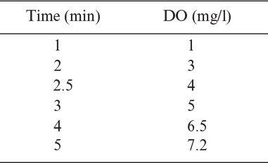
10.16. A stirred-tank reactor is to be scaled down from 10 m3 to 0.1 m3. The dimensions of the large tank are Dt = 2 m; Di = 0.5 m; N = 100 rpm.
a. Determine the dimensions of the small tank (Dt, Di, H) by using geometric similarity.
b. What would be the required rotational speed of the impeller in the small tank if the following criteria were used?
b1. Constant tip speed
b2. Constant impeller Re number
10.17. An autoclave malfunctions, and the temperature reaches only 119.5°C. The sterilization time at the maximum temperature was 20 min. The jar contains 10 l of complex medium that has 105 spores/l. At 121°C, kd = 1.0 min–1 and E0d = 90 kcal/g-mol. What is the probability that the medium was sterile?
10.18. You are asked to design a continuous sterilizer to produce 330,000 L/d of sterile media. The system must operate for 30 days with the probability of failure to be 0.001. The initial concentration of spores in the medium is 104/l. The value of kd is 1 min–1 at 121°C and 60 min–1 at 140°C.
a. Estimate the residence time in the sterilizer at 121°C necessary to achieve the desired probability of success.
b. Estimate the residence time required at 140°C.
c. What is the ratio of residence times for high-temperature, short-time sterilization to operation at 121°C?
10.19. One hundred tubes are to be sterilized. Each tube contains 10 mL of fluid. The value of kd = 0.6 min–1. The tubes are sterilized for 20 min. Ten of the tubes showed growth of contaminants. What was the concentration of spores in the tubes?