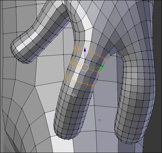
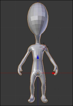
Before we sculpt our alien, we need to have a base mesh that has roughly its proportions. If you want, you can use the methods that you've learned in the previous chapter in order to model it, but here we are going to use a cool modifier that Blender has to offer: the Skin modifier. Its goal is to create a geometry around each vertex. We can simply extrude some vertices as if we were doing a real wire armature, and the Skin modifier will add volume around it. For each vertex, we have control over the volume size. Let's start our base mesh:
- We will start by entering in to the Edit Mode of our default cube. Then we will select all the vertices (A) and merge them to a sole vertex at the center (press Alt + M and click on the center). We now have our root vertex that will be the pelvis of our alien.
- It's now time to add a Skin modifier to our object in the modifier stack. As you can see, our vertex is controlling a new geometry around it. The geometry is low, so we will add a Subdivision surface modifier on top of the Skin modifier in order to have a smoother look. As you may have seen, the vertex has a red circle around it. This means that it is the root of our armature.
- We can now extrude our vertex (E) on the Z axis in order to start the torso of our alien.
- Now we will add a Mirror modifier with the Clipping option turned on. This modifier needs to be placed before the Skin and Subdivision Surface modifier (use the up and down arrows to move it to the first place). Ensure that the vertices that are on the symmetry axis are merged.
- We can now select the top vertex (the base of the neck) and extrude it by pressing Ctrl and LMB to the right in order to create the shoulder. Be careful with the position of your vertex as the topology generated could be bad. Always try to move your vertices a little bit in order to see whether you can't have a better topology.
- We will now change the size of the volume that has been generated around the shoulder vertex. To do this, we will use the Ctrl + A shortcut and we move our mouse to adjust it.
- We will then extrude the arm. In order to give a more dynamic shape, we will bend it at the elbow. We then adjust its size. At this point, it is very important to match the proportions of the concept. Proportions means the length and size of the different members with respect to each other. If you need to constrain the size or change the volume on a certain axis, you can press Ctrl + A + X, Y, or Z.
- Let's extrude the long neck of our alien.
- It's now time to add the legs of our alien. We will do this by extruding the pelvis vertex at a 45 degree angle (press Ctrl and LMB). Then we extrude the leg and adjust its profile by changing the size of the different vertices (Ctrl + A). As we did for the arm, we will bend the leg a little bit at the knee location. Note that the pelvis vertex should be always marked as the root of the armature. If this is not the case, select it and in the Skin modifier, press the Mark Root button.
- The foot will be then extruded and resized. We can create the heel by simply extruding the ankle vertex to the back. The ankle vertex needs to be marked as Loose in order to have a nice transition with the front and the heel of the foot. To do this, we select it and use the Mark Loose button in the Skin modifier.
- It's now time to create the hand by extruding the wrist vertex. From the new vertex, we will extrude three fingers that will be rescaled appropriately. Note that the thumb is at a 45 degree angle from the other fingers. To add a more dynamic feeling to the hand, we will slightly bend the fingers inwards.
- We will then extrude the base of the neck. From the newly created vertex, we can extrude the head vertex that will then be the base for the chin and the cranium.

The steps of the base mesh creation with the Skin modifier.
- We can now apply all our modifiers from the top to the bottom of the stack.
- If we enter in the Edit Mode, we can see that some parts are very dense. This is why we are going to remove some edge loops from certain parts such as the fingers. However, rather than doing this for both sides of the model, we are going to split the mesh in two and add a mirror modifier. To do this, we first need to ensure that there is a symmetry axis in the middle of our mesh. If this not the case, you can use the knife tool (K) to create it. Then we can delete half of our model and add a mirror modifier as we did in the previous chapter. We can now select some edge loops where there is a lot of condensed geometry by pressing Shift + Alt and the RMB, and by pressing X we can delete them (delete the edge loops, not the vertices or faces).

Removing some edge loops of the dense parts.
- The base mesh is now ready to be sculpted.

The final base mesh
While sculpting, it's nice to use Matcap. It is simply an image that will be projected on your mesh in the viewport and that looks like a material. For instance, you can use a Matcap that reminds you of clay. Let's begin with our sculpting:
- To set up a Matcap for our mesh, we will have to set up the default material of our mesh in the Properties panel under the Material tab (refer to 1 in the following screenshot). Note that if you can't see a material, you can press the New button.
- Now we will check the Shadeless option under the Shading subpanel (refer to 1 in the following screenshot).

Creation of a new material with the Shadeless option.
- As we have said before, a Matcap is an image, so we will import our image as the texture of our material. To do this, we go to the Texture tab (refer to 3 in the following screenshot) and we add a new texture by clicking on the New button. In the image subpanel, we will click on the Open button (refer to 4 in the following screenshot) and we choose our Matcap image.
- A Matcap is mapped to a mesh according to its normals, so in the Mapping subpanel change the Coordinates from UV to Normals (refer to 5 in the following screenshot). We will also adjust the size of our projection by decreasing the X, Y, and Z size sliders to 0.95 (refer to 6 in the following screenshot).

Setting the Matcap image texture for our material
- In order to see our Matcap in the viewport, we will replace the Multitexture display mode with GLSL in the right panel of the 3D view (N) under the Shading subpanel.
- Last but not least, we will go into the Shading mode under Texture Viewport using the corresponding drop-down menu in the 3D view header. You can also use the Alt + Z shortcut to quickly switch to this mode. Our Matcap is now perfectly set up!

Setting the GLSL display mode in the right panel of the viewport (N).
