Now that we've finished the house modeling, we will improve our scene with an environment composed of a cliff, a barrier, a cart, and some rocks.
- We will start by modeling its ground part. In order to do this, we add a plane and scale it.
- We will then move the ground, so the house is placed above it.
- We will use the scale tool in order to make the ground wider.
- In the side view, we will enter the Edit Mode and activate the wireframe (Z). We will select the two vertices in the front of the plane, and by pressing Ctrl and the LMB, we will extrude the cliff profile to the left.
- We will then reshape the geometry from a top view by moving the vertices with the Grab (G) tool. The cliff should be narrower where the house is.
- The whole geometry will then be extruded down to form the height of the cliff.

Starting the cliff modeling
- At this point, we can add some new horizontal loop cuts (Ctrl + R) in order to add definition to our model.
Now our goal is to give the impression of a rock with the few polygons that we have. To get the shape, we will go in the top view, and with the wireframe turned on, we will select the edges of the contour of the cliff and move them to form ridges and a valley. This will give an angular look. Remember that all the details will come with the texturing process in the next chapter, so we only have to give the overall shape here.
- We can improve the model with some randomness. To do this, we go in the Tool tab of the left 3D view panel, and under the Deform section of the Mesh Tools subpanel, we click on Randomize. The effect of the tool can be tweaked with the Amount slider in the last tool option panel. This tool will simply push all the individual selected components in a random direction.

The final cliff
- Lastly, we can arrange the global shape of our object with Proportional Editing. For instance, we can scale the tip of the cliff with it.
We are now going to learn a new way of modeling certain objects with curves. Curves are entities that can be useful to model ornaments, shoelaces, ropes, tree branches, and so on. In our case, we will model an entire tree with them.
Note
A word about curves
A curve is defined by control points that are connected together. Each point has a handle type. This can be changed by first selecting the control point that you want and by pressing the V key. By choosing the Vector type, the point will be angular. We are choosing Automatic or Aligned, so you will have Bezier handles that define the smoothness of the point. Handles always work in pairs. You can break their link by selecting the handle that you want to disconnect and by pressing V and select Free. In the beginning, you will find that curves are hard to manipulate, but with a little bit of practice, it will become as easy as pie. But, of course, there is lot more to discover about them!

- We will add a new curve of the Bezier type (press Shift + A and select Curve | Bezier). Then we will enter in the Edit Mode.
- We will then turn off the handles and the normals of the curve. To do this, we will uncheck the Handles and Normals check boxes under the Curve Display subpanel in the right 3D view panel (N).

The Curve display options in the N panel.
- When you start working on a shape that uses curves, it's easier to set all the control points as Vector (press V and select Vector).
- Now we will leave the Edit Mode and add a new curve object of the bezier circle type (press Shift + A and select Curve | Circle). This circle will define the volume of our bezier curves.
- We will select the bezier curve, and in the Properties editor, we will click on the object data icon. Under the Shape subpanel, we will then select the circle as the Bevel Object. As you can see, the curve is now getting a volume defined by the circle. If you change the circle, its scale, for instance, will change the curve volume.
- We will then close the holes on each side of the curve by checking the Fill caps option under the Bevel Object one.
- We can now modify our curve to form the trunk of the tree. To do this, we can simply vertically rotate the two points that we already have and extrude the tip several times with E or press Ctrl and LMB. You can also subdivide the curve by selecting at least two consecutive points and pressing W and select Subdivide.
- Now we can change the radius of each point by changing its value in the Transform subpanel in the left 3D view panel. This is how we will taper the trunk.
- We can now add new branches to our tree by simply adding a new point by pressing Ctrl and LMB without anything else selected. This point could then be extruded.
We can also change the radius of the branch. If you want to quickly select a branch, you can either select one of its points and press Ctrl + L, or select one of its points and press Ctrl and the + numpad key several times.
- We will now add more branches by duplicating the first one that we've created. The process simply involves the duplication and placement of a lot of branches that differ in size and radius.
- Next, we can convert our curves to a mesh object. In order to do this, we will have to first decrease the subdivision of our branches and our circle profile object by going to their Object data tab in the Properties editor and by changing the Preview U (for the viewport) and Render U (for the final render) sliders. We can now select our curve object and press Alt + C and select Mesh from Curve/Meta/Surf/Text to convert our curve object into polygonal geometry.

The curves option in the Properties editor
We will now show you how to deform the tree with a special type of object called a lattice. This will serve us to change the overall shape of it.
Note
What exactly is a lattice?
A lattice is a very useful object that is bound to another object. It is a cube that can be subdivided along three axes: U, V, and W. This needs to encapsulate the object to which it is bound. Then, when we move its control points, it performs a sort of a projection that allows us to deform the bound mesh.

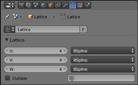
The Lattice options in the Properties editor.
- We will add a new lattice by pressing Shift + A as usual.
- Now that we have a new lattice, we can place it around our tree. No geometry should be outside the lattice or it will cause problems.
- We will now increase the subdivisions of the lattice in U, V, and W to 4. This will gives us enough control points in order to tweak our tree.
- Now it's time to bind our lattice to our tree by simply selecting our tree and adding a new Lattice modifier. We will now have to specify to Blender the lattice object that we want to bind to our mesh in the Object parameter. In our case, we only have one lattice so it's easy to find it in the list, but if you have many lattices, don't forget to name them.
- We can now enter Lattice Edit Mode and move the control points as if they were vertices.

The final tree with its lattice
We will now enhance our scene by adding some cool assets using the techniques that we've seen in this chapter:
- Let's start with the easiest asset, the rock. We will start this element with a cube.
- Now in Edit Mode, we will use the Subdivide smooth option (press W and select Subdivide smooth).
- In the last tool subpanel of the left 3D view panel, we can tweak the Fractal slider in order to add some randomness to the subdivision.
- We can now repeat steps 2 and 3 several times.

A single rock
- Now that we have a pretty spherical rock, we will use a Lattice modifier to shape it more like a rock. In our case, we will set our lattice with three subdivisions in U, V, and W, and after we've done the job, we will apply the modifier on the rock.
- We can now use the instance duplication (Alt + D) tool in order to populate our terrain with rocks. This is a little bit of cheating, but we don't have to do any other objects in order to give the impression that there are many different rocks. Indeed, we can simply rotate and scale the rocks in a random manner! In this case, the Free Rotation tool (press R key twice) is quite useful.

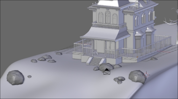
The rocks are now placed all around the house.
We will now create a barrier in front of the house with a very nice modifier.
- We will first add a new cube that we will scale on the x and y axes to make it thinner.
- Next, we can select the top face in the Edit Mode and move it to change the height of the plank.
- With the top face selected, we will extrude the top part of the plank and scale it on X.
- We can then select all the objects (A) and use the Bevel tool (Ctrl + B) to smooth their edges.

The barrier plank
- We can now place it on the far left of the cliff in front of the house.
- The next thing is to use the Array modifier in order to do a line of planks to the middle of the house.
- We can duplicate this barrier piece on the other side.
- In order to break the boring alignment of these objects a little bit, we will use a path curve (Shift + A and select Curve | Path) that will guide the planks.
- The path object looks like a curve. We can select each control point, extrude them, and subdivide them. We will extend the path object from the far left to the far right of the cliff and subdivide it several times (W and select Subdivide).
- We can now break the path by moving each control point in a random way.
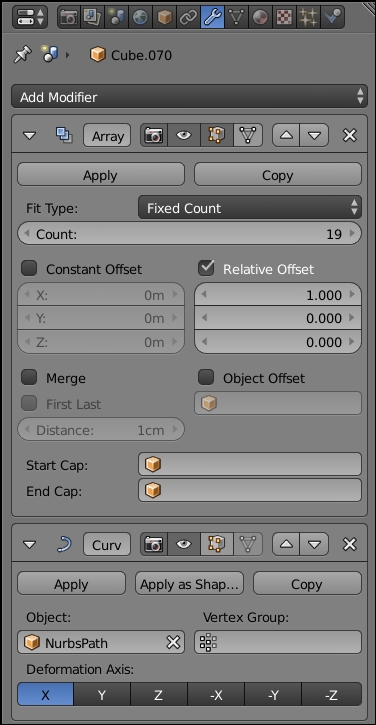
- On the barriers, we will add Curve modifiers and select our path as the object. In our case, the deformation axis is x. Be careful that curve modifier is placed above the array of the stack. Indeed, we want to deform only one plank. As you can see, we now have our barrier following the path.

The final barriers with their curve
The following screenshot shows the barrier modifiers:

The barrier modifiers
It's now time to model the cart, which is a more complex object, but still simple to do with all the tools you've learned until now:
- Let's start by duplicating one of the planks that we used in our physics simulation. This time we want to modify it without breaking the ones that are part of our simulation, so we press the U key and select Object & Data to make it a single user.
- We can now use an Array modifier to make the bottom part of our cart. We can specify a little margin between each of them.
- Now we will apply the modifier and tweak each plank so that they don't look the same.
- We will now add a small cube and change its height. We can break its silhouette a little bit with Loop Cut (Ctrl + R) that we will move, and finally, add a bevel.
- Now we can duplicate this object (Shift + D) at each corner of the cart.
- We can now add a small plane that we will extrude by following the outline of the cart. We will add a Solidify modifier and apply it.
- We can now add a new cube that we will shape into handles. As always, it's a matter of loop cuts, bevel, and placement.
- Now, the last thing we need is two big wheels. To do this, we will add a circle, and in the Edit Mode, we will extrude it along the normals (press E + Alt + S). We can also extrude the wheel to give it a thickness. Remember to check your normals' orientations and clean them with Ctrl + N if needed.
- Now we will add some radius. To do so, we first select one of the inner faces of the wheel, duplicate it and extrude it. We can select the whole radius and press P for Separate selection. We will also need to change its pivot point at the center of the wheel (press Ctrl + Alt + Shift + C and select At center).
- We then duplicate the wheel with Alt + D, and without validating the action, we will press R to rotate it. This is because now we can press Ctrl + R to repeat the duplication and rotation process. What a time saver!
- In order to cap the wheel, we will add a cylinder that will be extruded several times.
- Finally, we can duplicate the wheel on the other side with Alt + D and add a cylinder that will connect both wheels. Remember to delete the unneeded faces on each side.

The final cart
As you can see, the items that we created are quite simple, so we encourage you to add more of them, such as a dead trunk or a scarecrow. Be creative, you have all the tools needed to do that yourself.
