
Chapter 3. Architecture
That’s been one of my mantras—focus and simplicity. Simple can be harder than complex: You have to work hard to get your thinking clean to make it simple. But it’s worth it in the end because once you get there, you can move mountains.
—Steve Jobs
The architecture for Bluetooth low energy is fundamentally very simple. As shown in Figure 3–1, it is split into three basic parts: controller, host, and applications. The controller is typically a physical device that can transmit and receive radio signals and understand how these signals can be interpreted as packets with information within them. The host is typically a software stack that manages how two or more devices communicate with one another and how several different services can be provided at the same time over the radios. The applications use the software stack, and therefore the controller, to enable a use case.

Figure 3–1. The Bluetooth Architecture
Within the controller, there is both the Physical Layer and Link Layer as well as a Direct Test Mode and the lower layer of the Host Controller Interface. Within the host are three protocols: Logical Link Control and Adaptation Protocol, Attribute Protocol, and the Security Manager Protocol. Also within the host are the Generic Attribute Profile, the Generic Access Profile, and modes.
3.1. Controller
The controller is the bit that most people can identify as the Bluetooth chip or radio. Calling the controller a radio, however, is very simplistic; the controller is composed of both analog and digital parts of the radio frequency components as well as hardware to support the transmission and reception of packets. The controller interfaces with the outside world through an antenna and to the host through the Host Controller Interface.
3.1.1. Physical Layer
The Physical Layer is the bit that does the hard work of transmitting and receiving bits using the 2.4GHz radio. To lots of people, the Physical Layer is magical. Fundamentally, it is not magic, but is the simple transmission and reception of electromagnetic radiation. Typically, radio waves can carry information by varying the amplitude, frequency, or phase of the wave within a given frequency band. In Bluetooth low energy, the frequency of the radio waves are varied to allow either a zero or a one to be exposed, using a modulation scheme called Gaussian Frequency Shift Keying (GFSK).
The Frequency Shift Keying part means that ones and zeros are coded onto the radio by slightly shifting the frequency up and down. If the frequency is shifted abruptly to one side or the other at the moment the frequency changes, there is a pulse of energy that spreads out over a wider range of frequencies. So a filter is used to stop the energy spreading too far into higher or lower frequencies. In the case of GFSK, the filter used is shaped like a Gaussian curve. The filter used for Bluetooth low energy is not as tight as the filter used for Bluetooth classic. This means that the low energy radio signal spreads out a little more than the classic radio signal.
This slight widening of the radio signal is useful because it means the radio comes under spread-spectrum radio regulations, whereas the Bluetooth classic radio is governed by frequency-hopping radio regulations. Spread-spectrum radio regulations allow a radio to transmit on fewer frequencies than frequency-hopping radio regulations. Without the more relaxed filter shape, the Bluetooth low energy radio would not be allowed to advertise on just three channels; it would have to use many more channels, which would make the system higher power (as discussed earlier).
This slight widening of the radio signal is referred to as the modulation index. Modulation index describes how wide the upper and lower frequencies used are around the center frequency of a channel. When the radio signal is transmitted, a positive frequency deviation of more than 185kHz from the center frequency represents a bit with the value 1; a negative frequency deviation of more than 185kHz represents a bit with the value 0.
For the Physical Layer to work, especially when lots of other radios are in the same area transmitting at the same time, the 2.4GHz band is split up into 40 separate RF channels, each 2MHz apart from one another. The Physical Layer transmits information at one bit of application data every one microsecond. For example, to send the 80 bits of data for the string “low energy” formatted in UTF-8 would take just 80μs, although this does not take into account any packet overhead.
3.1.2. Direct Test Mode
Direct Test Mode is a novel approach to the testing of the Physical Layer. In most wireless standards, there is no standard way to get a device to perform standard Physical Layer tests. This leads to the problem of many different companies building their own proprietary methods to test only their Physical Layers. This increases the costs for the whole industry and increases the barriers for an end-product manufacturer to change from one silicon supplier to another quickly.
Direct Test Mode allows a tester to command a controller’s Physical Layer to either transmit a sequence of test packets or receive a sequence of test packets. The tester can then analyze the packets received, or the number of packets that the device under test received, to determine if the Physical Layer is working according to the specification. The tester can also measure various RF parameters from received packets to determine if the Physical Layer is compliant with the RF specs. The Direct Test Mode is not just applicable to qualification testing; it can also be used for production line testing and calibration of radios. For example, by quickly commanding a Physical Layer to transmit on a given radio frequency, and measuring the actual transmitted signal, the radio can be tuned to match what it should be doing. This sort of calibration is typically done on every single unit, so having test equipment that can do this efficiently can save product manufacturers money.
3.1.3. Link Layer
The Link Layer is probably the single most complex part of the Bluetooth low energy architecture. It is responsible for advertising, scanning, and creating and maintaining connections. It is also responsible for ensuring that packets are structured in just the right way, with the correctly calculated check values and encryption sequences. To do this, three basic concepts are defined: channels, packets, and procedures.
There are two types of Link Layer channels: advertising channels and data channels. Advertising channels are used by devices that are not in a connection sending data. There are three advertising channels—again, this is a compromise between low power and robustness. Devices use these channels to broadcast data, advertise that they are connectable and discoverable, and to scan and initiate connections. The data channels are only used once a connection has been established and data needs to flow. There are 37 data channels, and they are used through an adaptive frequency-hopping engine to ensure robustness. The data channels allow data from one device to another to be sent, acknowledged, and, if necessary, retransmitted. Data channels can be encrypted and authenticated on a per-packet basis.
To send data on any of these channels (data or advertising), small packets are defined. A packet encapsulates a small amount of data that is sent from a transmitter to a receiver over a very short period of time. Packets include information to identify the intended receiver, as well as a checksum that ensures that the packet is valid. The basic packet structure is identical between the advertising channels and data channels, with a minimum of 80 bits of addressing, header, and check information included in each and every packet. Figure 3–2 presents an overview of the Link Layer packet structure.
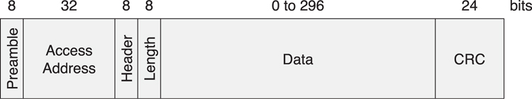
Figure 3–2. The Link Layer packet structure
The packets are optimized to increase their robustness by using an 8-bit preamble that is sufficiently large to allow the receiver to synchronize bit timing and set the radio’s automatic gain control; a 32-bit access address that is fixed for advertising packets but completely random and private for data packets; an 8-bit header to describe the contents of the packet; an 8-bit length field to describe the payload length, although not all these bits are used for length because no packet with more than 37 octets of payload is allowed to be sent; a variable-length payload that contains useful data from the application or the host device stack; and finally, a 24-bit cyclic redundancy check (CRC) value to ensure that there are no bit errors in the received packet.
The shortest packet that can be sent is an empty data packet that is 80μs in length, whereas the longest packet is a fully loaded advertising packet that is 376μs in length. Most advertising packets are just 128μs in length, and most data packets are 144μs in length.
3.1.4. The Host/Controller Interface
For many devices, a Host/Controller Interface (HCI) will be provided that allows a host to communicate with the controller though a standardized interface. This architectural split has proven to be extremely popular in Bluetooth classic, for which over 60 percent of all Bluetooth controllers are used through the HCI interface. It allows a host to send commands and data to the controller and the controller to send events and data to the host. It is really composed of two separate parts: the logical interface and the physical interface.
The logical interface defines the commands and events and their associated behavior. The logical interface can be delivered over any of the physical transports, or it can be delivered via a local application programming interface (API) on the controller, allowing an embedded host stack to be included within the controller.
The physical interface defines how the commands, events, and data are transported over different connection technologies. The physical interfaces that are defined include USB,1 SDIO,2 and two variants of the UART.3 For most controllers, they will support just one or possibly two interfaces. It should also be considered that to implement a USB interface requires lots of hardware, and the interface is not the lowest power interface, so it would not typically be provided on a Bluetooth low energy single-mode controller.
Because the host controller interface has to exist on both the controller and the host, the part that is in the controller is typically called the lower-host controller interface; the part that is in the host is typically called the upper-host controller interface.
3.2. The Host
The host is the unsung hero of the Bluetooth world. The host contains multiplexing layers, protocols, and procedures for doing lots of useful and interesting things. The host is built on top of the upper-host controller interface. On top of this is the Logical Link Control and Adaptation Protocol, a multiplexing layer. On top of this are two fundamental building blocks for the system; the Security Manager that does everything from authentication and setting up secure connections and the Attribute Protocol that exposes the state data on a device. Built on the Attribute Protocol is the Generic Attribute Profile that defines how the Attribute Protocol is used to enable reusable services that expose the standard characteristics of a device. Finally, the Generic Access Profile defines how devices find and connect with one another in an interoperable manner.
There is no defined upper interface for the host. Each operating system or environment will have a different way of exposing the host APIs, whether that be through a functional or object-oriented interface.
3.2.1. Logical Link Control and Adaptation Protocol
The Logical Link Control and Adaptation Protocol (also referred to as L2CAP) is the multiplexing layer for Bluetooth low energy. This layer defines two basic concepts: the L2CAP channel and the L2CAP signaling commands. An L2CAP channel is a single bidirectional data channel that is terminated at a particular protocol or profile on the peer device. Each channel is independent and can have its own flow control and other configuration information associated with it. Bluetooth classic uses most of the features of L2CAP, including dynamic channel identifiers, protocol service multiplexers, enhanced retransmission, and streaming modes. Bluetooth low energy just takes the absolute minimum of L2CAP.
In Bluetooth low energy, only fixed channels are used: one for the signaling channel, one for the Security Manager, and one for the Attribute Protocol. There is only one frame format, the B-frame; this has a two-octet length field and a two-octet channel identifier field, as illustrated in Figure 3–3. This is the same frame format that classic L2CAP uses for every channel until the frame formats are negotiated to something more complex. For example, in Bluetooth classic, it is possible to have frame formats that include additional frame sequencing and checks. These are not needed in Bluetooth low energy because the checks at the Link Layer are strong enough to not need additional checks, and the simple Attribute Protocol has no need for out-of-order delivering of packets from multiple channels. By keeping the protocols simple and doing sufficient checks, only one frame format was required.
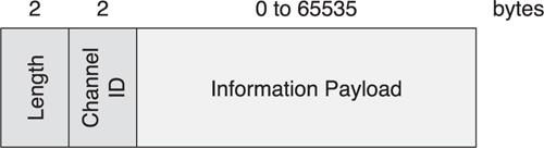
Figure 3–3. The L2CAP packet structure
3.2.2. The Security Manager Protocol
The Security Manager defines a simple protocol for pairing and key distribution. Pairing is the process of attempting to trust another device, typically by authenticating the other device. Pairing is typically followed by the link being encrypted and the key distribution. Using key distribution, shared secrets can be distributed from a slave to a master so that when these two devices reconnect at a later date, they can quickly prove their authenticity by encrypting using the previously distributed shared secrets. The Security Manager also provides a security toolbox for generating hashes of data, generating confirmation values, and generating short-term keys used during pairing.
3.2.3. The Attribute Protocol
The Attribute Protocol defines a set of rules for accessing data on a peer device. The data is stored on an attribute server in “attributes” that an attribute client can read and write. The client sends requests to the server and the server responds with response messages. The client can use these requests to find all the attributes on a server and then read and write these attributes. The Attribute Protocol defines six types of messages: 1) requests sent from the client to the server; 2) responses sent from the server to the client in reply to a request; 3) commands sent from the client to the server that have no response; 4) notifications sent from the server to the client that have no confirmation; 5) indications sent from the server to the client; and 6) confirmations sent from the client to the server in reply to an indication. So, both client and server can initiate communication with messages that require a response, or with messages that do not require a response.
Attributes are addressed, labeled bits of data. Each attribute has a unique handle that identifies that attribute, a type that identifies the data stored in the attribute, and a value. For example, an attribute with the type Temperature that has the value ![]() could be contained within an attribute with the handle 0x01CE. The Attribute Protocol doesn’t define any attribute types, although it does define that some attributes can be grouped, and their group semantics can be discovered via the Attribute Protocol.
could be contained within an attribute with the handle 0x01CE. The Attribute Protocol doesn’t define any attribute types, although it does define that some attributes can be grouped, and their group semantics can be discovered via the Attribute Protocol.
The Attribute Protocol also defines that some attributes have permissions: permissions to allow a client to read or write an attribute’s value, or only allow access to the value of the attribute if the client has authenticated itself or has been authorized by the server. It is not possible to discover explicitly an attribute’s permissions; that can only be done implicitly by sending a request and receiving an error in response, stating why the request cannot be completed.
The Attribute Protocol itself is mostly stateless. Each individual transaction—for example, a single read request and read response—does not cause state to be saved on the server. This means that the protocol itself requires very little memory. There is one exception to this: the prepare and execute write requests. These store a set of values that are to be written in the server and then executed all in sequence, in a single transaction.
3.2.4. The Generic Attribute Profile
The Generic Attribute Profile sits above the Attribute Protocol. It defines the types of attributes and how they are used. It introduces a number of concepts, including “characteristics,” “services,” “include” relationships between services, and characteristic “descriptors.” It also defines a number of procedures that can be used to discover the services, characteristics, and relationships between services, as well as read and write characteristic values.
A service is an immutable encapsulation of some atomic behavior of a device. This is a long stream of very complex words, but it is a very simple concept to understand. Immutable means that once a service is published, it cannot change. This is necessary because for a service to be reused it can never be changed. As soon as a service’s behavior changes, version numbers and other awkward setup procedures and configuration take time and therefore become the antithesis of a connectionless model, one of the basic concepts behind Bluetooth low energy.
Encapsulation means expressing features of something succinctly. Everything about a given service is enclosed and expressed through a set of attributes in an attribute server. Once you know the bounds of a service on an attribute server, you know what information that service is encapsulating. Atomic means of or forming a single irreducible unit or component of a larger system. Atomic services are important because the smaller the server, the more likely it is to be reusable in another context. If we created complex services that had multiple, possibly related behaviors, the chance of these being reused is significantly reduced.
Behavior means the way something acts in response to a particular situation or stimulus. For services, the behavior means what happens when you read or write an attribute, or what causes the attribute to be notified to the client. Explicitly defined behavior is very important for interoperability. If a service is specified with poorly defined behavior, each client might act in a different way when interacting with the service. The services might then act differently depending on which client is connecting, or more important, the same service on different devices will act differently. As soon as this becomes entrenched in the devices, interoperability is destroyed. Therefore, explicitly defined behavior that is testable, even for erroneous interactions, promotes interoperability.
Service relationships are key to the complex behaviors that devices expose. A service is atomic by nature. Complex behaviors should not be exposed in just a single service. Take, for example, a device that can measure the room temperature by exposing a temperature service. The device might be powered by a battery so it would expose a battery service. However, if the battery also has a temperature sensor, we should be able to expose another instance of the temperature service on the device. This second temperature service needs to be related to the battery so that a client can determine that relationship. This is shown in Figure 3–4.

Figure 3–4. Complex service relationships
To accomodate complex behaviors and relationships between services, services come in two types: primary services and secondary services. The type of a service is not typically dependent on the service itself but on how that service is used in a device. A primary service is one that exposes what the device does, from the perspective of the user. A secondary service is one that is used by a primary service or another secondary service to enable it to provide its complete behavior. In the previous example, the first temperature service would be a primary service, the battery service would also be a primary service, whereas the second instance of the temperature service—the temperature of the battery—would be a secondary service referenced from the battery service.
3.2.5. The Generic Access Profile
The Generic Access Profile defines how devices discover, connect, and present useful information to the users. It also defines how devices can create a permanent relationship, called bonding. To enable this, the profile defines how devices can be discoverable, connectable, and bondable. It also describes how devices can use procedures to discover other devices, connect to other devices, read their device name, and bond with them.
This layer also introduces the concept of privacy by using resolvable private addresses. Privacy is important for devices that are constantly advertising their presence so that other devices can discover and connect to them. Devices that want to be private, however, must broadcast by using a constantly changing random address so that other devices cannot determine which device it is by listening, or which device is moving around by tracking its current random address over time. However, to allow devices that are trusted to determine if it is nearby, and to allow connections, the private address must be resolvable. The Generic Access Profile, therefore, defines not only how private addresses are resolvable but also how to connect to devices that are private.
3.3. The Application Layer
Above the controller and the host is the Application Layer. The Application Layer defines three types of specifications: characteristic, service, and profile. Each of these specifications is built on top of the Generic Attribute Profile. The Generic Attribute Profile defines grouping attributes for characteristics and services, and the applications define the specifications that use these attribute groups.
3.3.1. Characteristics
A characteristic is a bit of data that has a known format labeled with a Universally Unique Identifier4 (UUID). Characteristics are designed to be reusable, and therefore have no behavior. As soon as behavior is added to something, it limits its reuse. The most interesting thing about characteristic specifications is that they are defined in a computer-readable format rather than as human-readable text. This gives computers the ability, when they see a characteristic used for the first time, to download this computer-readable specification and use it to display these characteristics to the user.
3.3.2. Services
A service is a human-readable specification of a set of characteristics and their associated behavior. The service only defines the behavior of these characteristics on a server; the service does not define the client behavior. For many services, the client behavior can be implicitly determined by the service’s server behavior. However, for some services, there might need to be more complex behavior in the client that must be defined. This client behavior is defined in profiles, not in the services.
Services can include other services. The parent service can only define the services that are included; it cannot change the characteristics in these included services or change the behavior of these services. The including service, however, can describe how multiple included services interact with each other.
Services come in two variants: primary and secondary, as noted in Section 3.2.4. The primary or secondary nature of a service can be defined in a service specification or can be left up to the profile or an implementation. Primary services are those that embody what a given device does—it is these services that the user would understand that the device does. Secondary services are those that assist the primary services or other secondary services.
Services do not describe how devices connect to each other to find and use services. Services only describe what happens when a characteristic is read or written, or when it is notified or indicated. Services do not describe what Generic Attribute Profile procedures are used to find the service, the characteristics within a service, or how the characteristics are used by a client.
3.3.3. Profiles
Profiles are the ultimate embodiment of a use case or application. Profiles are specifications that describe two or more devices, with one or more services on each device. Profiles also describe how the devices should be discoverable and connectable, thereby defining what topology is necessary on each device. Profiles also describe the client behavior for finding the service, finding the characteristics of the service, and using the service to enable the functionality required by the use case or application.
There is a many-to-many mapping of profiles to services, as illustrated in Figure 3–5. A service can be used by many profiles to enable a given behavior on a device. The behavior of a service is independent of which profile is using this service at this time. Application stores can be given the list of services that a device supports and find the set of applications from the store that use these services. This flexibility enables a plug-and-play model that has worked so well for the universal serial bus.
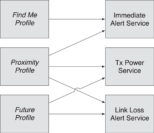
Figure 3–5. Complex profile service relationships
3.4. Stack Splits
It is possible to build a Bluetooth low energy product by using multiple different stack splits. The specification defines one stack split using the host controller interface between the controller and the host, but you can use many other different stack splits.
3.4.1. Single-Chip Solutions
The simplest stack split that is possible with Bluetooth low energy is the single-chip solution, as shown in Figure 3–6. This has no stack splits; all parts of the product are packed into a single chip. This chip includes the controller, the host software, and the applications. This is the ultimate in low-cost products, only requiring a source of power, an antenna, some hardware to interface to—for instance, buttons and lights—and some additional discrete components.
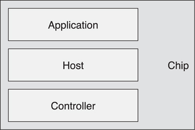
Figure 3–6. A single-chip solution
Unfortunately, there are some downsides to using single-chip solutions. First, the development environments are more difficult to use because the chips are very resource constrained. Second, to reduce the cost, the software needs to be burned into read-only memory (ROM) in the chip. This requires a custom chip to be made for a single product. This can be offset by the reduced bill of materials for very large production runs, but the process can be very expensive for smaller production runs.
For devices that have small production runs or for prototype products, a mass-produced single chip that includes everything from the controller up to the top of the host can be used with a small nonvolatile memory chip to store the application. This yields very low-cost small production runs. At power up, the contents of the non-volatile memory are read into the single chip and executed. Thus, you can have both an efficient prototyping platform and a cost-effective small production run product.
3.4.2. Two-Chip Solutions
For two-chip solutions, the classic model is that the controller is on one chip and the host and applications are on a separate chip, as shown in Figure 3–7A. This model is typically used for cell phones and computers because they already have very powerful processors capable of running the complete host and application software stack. This solution typically uses mass-produced controller chips with a standard Host Controller Interface. Although this architectural split is ideal for devices that already have a very powerful processor, it is not ideal for any other type of device.
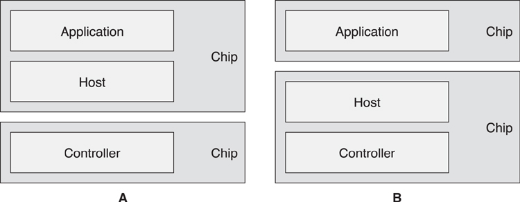
Figure 3–7. A pair of two-chip solutions
An alternative two-chip solution is one in which the controller and host are on one chip, and the applications are on a separate chip, as shown in Figure 3–7B. This has the advantage that the application chip can be a very small low-power microprocessor because the application chip doesn’t need much memory or other resources to run the application. The interface between the two chips would typically be a custom interface, probably employing a simple UART. This solution has the advantage that two standard mass-produced chips can be combined and use the standard development tools for the application chip.
3.4.3. Three-Chip Solutions
It is also possible for multiple-chip solutions to be used. For example, it would be possible to combine a standard controller on one chip, with a host chip and an application chip, as shown in Figure 3–8. The host chip would require two separate interfaces.
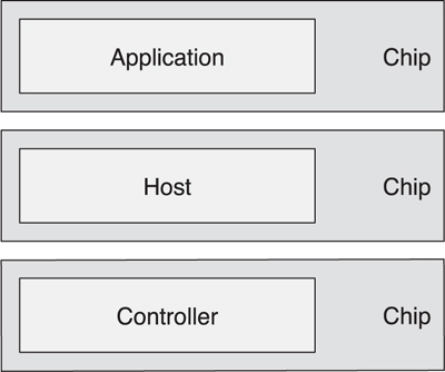
Figure 3–8. A three-chip solution
These solutions are typically prohibitively expensive; therefore, they are typically confined to development systems where multiple interfaces are used to allow each layer to be separately instrumented. Short production runs might also be able to tolerate this complexity because the cost of integrating into fewer components is not offset by the savings on each end product if only a few products are ever to be manufactured. For mass-produced products, this architecture would never be viable from a cost point of view.