
12
Energy Harvesting Enabled Body Sensor Networks
12.1 Introduction
Wireless and embedded systems are commonly powered using batteries and, over time, there has been advances in creating low-power and energy-efficient systems to enable running for a longer time while consuming less energy. For applications where the system is expected to operate for longer, energy becomes a severe bottleneck and much research effort needs to be spent on the efficient use of battery energy while creating new technologies. Recently, another alternative, namely harvesting energy from the environment, has been explored to supplement or even replace batteries.
Sensor networks typically are required to run for a long time, often several years, and are only powered by batteries. This makes energy awareness a major issue when designing these networks. Finite battery capacity is therefore a limitation in the battery-powered networks. This consequently limits the lifetime of the wireless sensor network (WSN) applications or additional cost and complexity to regularly change the batteries. On the other hand, depleted batteries constitute environmental pollution and hazards.
While the technology in battery design is constantly improving and the power requirement of electronics is also dropping, they are not keeping pace with the increasing energy demands of many WSN applications. Therefore, there has been considerable interest in the development of systems capable of extracting sufficient electrical energy from existing environmental sources.
The energy required by the sensors is consumed mostly for wireless communications, and it depends on the communication range. Some energy is also required for recording (or sensing) and processing the sensor data either by the sensors themselves or by the processing machines such as mobile phones or PCs. The data processing power is highly dependent on the working frequency, sampling frequency, and the computation cost for each particular algorithm. In addition, different communication systems require different energy consumptions. Increasing the data size, by adding overheads before transmission, for error protection, or security purposes further increases the energy demand. Table 12.1 shows the energy requirement for three different commercial nodes.
Table 12.1 Power consumption for Crossbow MICAz [1], Intel IMote2 [2], and Jennic JN5139 [3] commercial sensor network nodes (clock speed between 13 and 104 MHz).
Source: Courtesy of Xbow.
| Crossbow MICAz | Intel IMote2 | Jennic JN5139 | |
| Radio standard | IEEE 802.15.4/ZigBee | IEEE 802.15.4 | IEEE 802.15.4/ZigBee |
| Typical range | 100 m (outdoor), 30 m (indoor) | 30 m | 1 km |
| Data rate (kbps) | 250 kbps | 250 kbps | 250 kbps |
| Sleep mode (deep sleep) | 15 μA | 390 μA | 2.8 μA (1.6 μA) |
| Processor only | 8 mA active mode | 31–53 mA* | 2.7 + 0.325 mA/MHz |
| RX | 19.7 mA | 44 mA | 34 mA |
| TX | 17.4 mA (+0dbm) | 44 mA | 34 mA (+3 dBm) |
| Supply voltage (minimum) | 2.7 V | 3.2 V | 2.7 V |
| Average | 2.8 mW | 12 mW | 3 mW |
12.2 Energy Conservation
The efficient use of available energy in a network is always one of the fundamental metrics. This is even more critical for a body sensor network (BSN) or WSN where the nodes have limited power. Thus, in order to reduce energy consumption, a practical and efficient approach is to reduce the transmission power. On the other hand, the need for sensor power directly depends on the on-sensor processing capability, which can be very different from relay sensors or those directly connected (mostly through wire) to a separate processor.
Considering the wireless channel and energy consumption models in WSN, one observation is that, instead of using a long, energy-inefficient edge, the nodes should choose a multihop path composed of short edges that connect the two endpoints of a long distance (edge) for communication [4]. This observation is a fundamental idea in topology control to reduce energy consumption. Therefore, the topology control algorithms in a battery-powered WSN aim to choose short links between the nodes while preserving network connectivity. However, in an energy harvesting wireless sensor network (EH-WSN), with renewable energy the nodes need to manage the required energy smartly. This also depends on how they choose, communicate, or deal with their neighbouring sensors. In a smart EH-WSN each node should choose its neighbours based on not only its own energy consumption but also the energy levels available to its neighbours.
12.3 Network Capacity
Network capacity is the amount of traffic or the maximum data speed that a communication network can tolerate. In a wireless network, the communications share the same medium. This implies the existence of undesired noise, interference, attenuation, and multipath during communication, which negatively affect the network traffic capacity. The effects of various artefacts can be reduced by increasing the transmitted power. This in return requires more energy. An ideal situation is that the transmission range is reduced to minimise the overlapping area. A practical approach to decrease interference is to set their transmission power to the desired value, such that the transmission ranges are limited. However, if the transmission power is reduced too much, the network may be disconnected. So, when designing a topology control algorithm, it is necessary to keep a balance between the connectivity and the network performance. There is more on the topology control concept in a later section of this chapter.
12.4 Energy Harvesting
Energy harvesting is an approach to capture, harvest, or search an ambient energy and convert it into electrical energy which is directly used or stored-then-used for sensing or actuation. The captured energy by sensors is generally very small as compared to large-scale energy harvesting using renewable energy sources, such as solar and wind farms. Unlike the large-scale power stations which are fixed at a given location, the small-scale energy sources are portable and readily available for use. Energy harvested from the ambient environment are used to power small autonomous sensors that are deployed in remote locations for sensing or even to endure long-term experience to hostile environments. The operations of these small independent sensors are often restricted by a reliance on battery energy. Hence, the driving force behind the search for energy-harvesting practice is the desire to power WSNs and moveable devices for extended operation with the supplement of the energy storage elements if not completely avoiding the storage elements such as batteries. EH-WSNs can provide a solution to the energy problem by harvesting energy that already exists in the surrounding environment. If the harvested energy source is large and constantly (or periodically) available, a sensor node can be powered perpetually. In this way, the energy is essentially infinite; however, this is not always available.
Despite solar and wind energy, which have become very popular, one interesting example is vibration, which can power up WSNs. Vibration energy harvesting is the process by which otherwise wasted vibration (such as from a piece of industrial machinery) is harvested and converted to useful electrical energy to continuously power wireless sensor nodes. As an example, for system health monitoring application, a WSN can be used to monitor vibrations of a rotating machine and by analysing the vibrations in frequency domain to determine when the machine is going to fail and schedule the maintenance in time before the machine malfunctions. The fact that the WSN is being powered by the same vibration it's measuring allows the system to continuously monitor the machine's operation without the risk of the node running out of power.
Energy harvesting introduces a change to the fundamental principles based on which the necessary protocols for WSNs are designed. Instead of focusing on energy-efficient protocols that aim to maximise a sensor's lifetime, the main design objective in EH-WSNs is to maximise the network performance given the rate of available energy to be harvested from the environment. In other words, the surplus of harvested energy can be used to improve network performance. In general, energy harvesting provides numerous benefits to the end user. Some of the major benefits of energy harvesting suitable for WSNs are stated and elaborated in the following list.
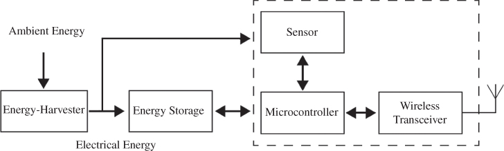
Figure 12.1 A typical node in an energy harvesting sensor network [5].
Source: Courtesy of Seah, W.K.G., Tan, Y.K., and Chan, A.T.S.
Energy-harvesting technology provides numerous benefits, such as:
- Reducing the dependency on battery power. This is mainly because the nodes eliminate the use of battery power. The harvested ambient energy may be sufficient to eliminate the need for batteries completely.
- Reducing installation and maintenance costs by avoiding service visits to replace the batteries and avoiding other problems such as battery wearing if the batteries are rechargeable.
- Providing long-term solutions to design and deploy reliable nodes with energy-harvesting devices which can function in the cases where the ambient energy becomes unavailable to make it perfectly suited for long-term applications.
A typical node in EH-WSN can be viewed in Figure 12.1. Often, there are actuators which are triggered by the microcontroller which is responsible for processing and control, and normally consumes a large amount of energy. The microcontroller itself consumes energy depending on the processing load, information volume, sampling frequency, and speed.
12.5 Challenges in Energy Harvesting
Potential sources of energy harvesting are all around us. Examples include light, radio signals propagating through the air, wind, different kinds of vibration, and movement. With new materials and ways of transforming energy, efficiency of harvesting has risen to the level that can be used for powering WSNs. Nevertheless, harvesting sources are not powerful enough yet to allow the continuous operation of sensor nodes powered by energy harvesting. Therefore, effective design and optimisation of the system is necessary.
The first stage of design is finding a way of converting ambient energy to electrical energy. Harvesting light and vibration energy through use of small-scale solar cells for light harvesting and macro fibre composites for capturing vibration energy have become popular in recent applications. In order to harvest maximum energy from the source, the load on the circuit producing energy needs to be matched through appropriate circuitry and the load is always application-specific, making it hard to implement.
Another energy-harvesting example can be extracting energy from the ocean tides, which is technically more challenging as the tide peaks need to be effectively harvested to empower the energy source.
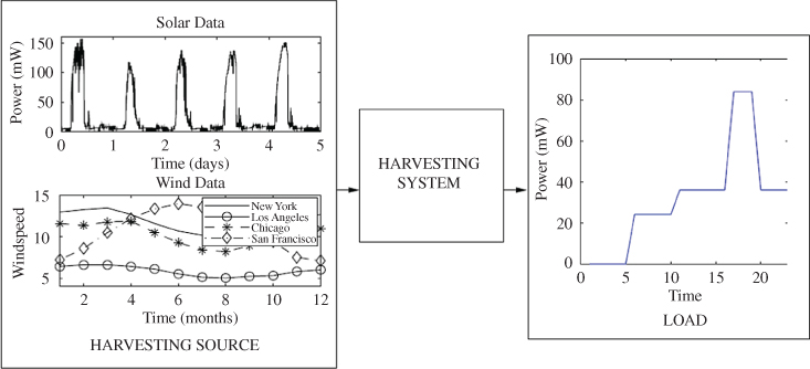
Figure 12.2 Environment (solar and wind) energy harvesting [6].
Source: Courtesy of Kansal, A., Hsu, J., Zahedi, S., and Srivastava, M.B.
The second stage is to manage the energy stored in the most efficient way. The system needs to be in charge of selecting when and how the energy is distributed throughout the system being powered by it. Furthermore, this block needs to minimise the leakage from the storage and have the smallest possible quiescent current.
The third stage is the application running on the node. This can be very different depending on the sensor technology and functionality. For battery-powered systems the main challenge lies in prolonging the battery life, but with energy harvesting the designer is aware that the energy storage will be replenished. Therefore, other approaches, such as using the power when harvesting and keeping dormant when no energy is harvested, can be utilised. Changing the duty cycle of operation depending on the energy level may be another option.
The environment energy varies with time depending on the environmental conditions which are often outside the designer's control. For instance, Figure 12.2 shows two possible power output variations over time: a solar cell output on a diurnal scale and wind speeds at four arbitrarily chosen locations [7] over a year. In a distributed system, multiple such harvesting sources may be present at multiple nodes at different locations [6].
In a battery-powered device, the typical power management design goals are to minimise the energy consumption and to maximise the lifetime of the device while meeting the required performance constraints. In an energy-harvesting node, one mode of usage is to treat the harvested energy as a supplement to the battery energy and, again, a possible power management objective is to maximise its lifetime. However, in the case of harvesting nodes, another usage mode is possible: using the harvested energy at an appropriate rate such that the system continues to operate perennially. This mode may be called energy neutral operation. A harvesting node is said to achieve energy neutral operation if a desired performance level can be supported for ever (subject to hardware failure). In this mode, power management design considerations are very different from those of maximising lifetime. Two design considerations are apparent:
- Energy neutral operation. How to operate such that the consumed energy is always less than the harvested energy? The system may have multiple distributed components each harvesting its own energy. In this case, the performance not only depends on the spatiotemporal profile of the available energy but also on how this energy is used to deliver network-wide performance guarantees.
- Maximum performance. While ensuring energy neutral operation, what is the maximum performance level that can be supported in a given harvesting environment? Again, this depends on the harvested energy at multiple distributed components.
For a simple scenario with a single sensor, a naive approach would be to develop a harvesting technology whose minimum energy output at any instant is sufficient to supply the maximum power required by the load. This, however, has several disadvantages, such as high cost, and may not even be feasible in many situations. For instance, when harvesting solar energy, the minimum energy output for any solar cell would be zero at night and this can never be made more than the power required by the load. A more reasonable approach is to add a power management system between the harvesting source and the load, which attempts to satisfy the energy consumption profile from the available generation profile (Figure 12.2).
In Figure 12.2 ‘HARVESTING SYSTEM’ refers to the system designed specifically to support a variable load from a variable energy-harvesting source when the instantaneous power supply levels from the harvesting source are not exactly matched to the consumption levels of the load. In a harvesting network, this may also involve collaboration among the power management systems of the constituent nodes to support distributed loads from the available energy. On the other hand, ‘LOAD’ refers to the energy consuming activity being supported. A load, such as a sensor node, may consist of multiple subsystems, and energy consumption may be variable for its different modes of operation. For instance, the activity may involve sampling a sensor signal, transmitting the sensed value, and receiving an acknowledgment.
There are two ways in which the load requirements may be reliably fed from a variable supply. One is to use an energy storage unit in the harvesting system such as a battery or an ultra-capacitor. Another is to modify the load consumption profile according to the availability. In practice, neither of these approaches alone may be sufficient since the load cannot be arbitrarily modified, and energy storage technologies have nonideal behaviour that causes energy loss.
A fourth stage can be added to the system in Figure 12.3 to enable scheduling the sensors, systems, or appliances which use the energy. This can happen if a group of nearby sensors can make a wired network to enable energy transfer. Following this concept, which stems from cooperative networking theory [9–11], the overall energy can be reduced and intelligently distributed among the sensors in a neighbourhood.
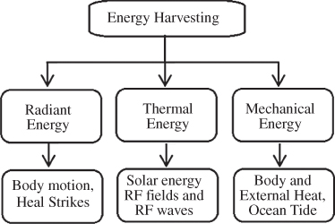
Figure 12.3 Some methods of energy harvesting [8].
Source: Courtesy of Vijayaraghavan, K., and Rajamani, R.
Much research and development work has been carried out on harnessing large-scale energy from various renewable energy sources, such as solar, wind, and water/hydro [12]. Little attention has been paid to small-scale energy-harvesting methods and strategies in the past as there hasn't been any need for it. Owing to the recent increase in small-scale sensor demands, there is quite a significant amount of research recorded in the literature that discusses scavenging or harvesting small-scale environmental energy for low-powered mobile electronic devices, especially wireless and wearable devices and sensors.
12.6 Types of Energy Harvesting
Figure 12.3 shows numerous types of ambient energy forms appropriate for energy harvesting along with examples of the energy sources. The energy types are thermal energy, radiant energy, and mechanical energy [8]. Substantial research has been devoted to the extraction of energy from kinetic motion. There are other vibration-based energy-harvesting techniques being reported, for instance piezoelectric generators, wearable electronic textiles, and electromagnetic vibration-based micro generator devices for intelligent sensor systems. In the thermal energy-harvesting research domain, consider the system design aspects for thermal energy scavenging via thermoelectric conversion that exploits the natural temperature difference between the ground and the air. Similarly, thermal energy harvesting through thermoelectric power generation from body heat to power wireless sensor nodes has been researched. Research on small-scale wind energy harvesting has also been performed by several groups of researchers [13].
Figure 12.4 further expands Figure 12.3 to show the common energy sources suitable for energy harvesting and their extraction techniques. Although for BSN very few of these energy sources are applicable, here we briefly look at the nature of these sources, their corresponding extraction techniques, along with some of their general applications. Despite the mechanism in energy harvesting, the efficiency in harvesting one type of energy is different from those for others.
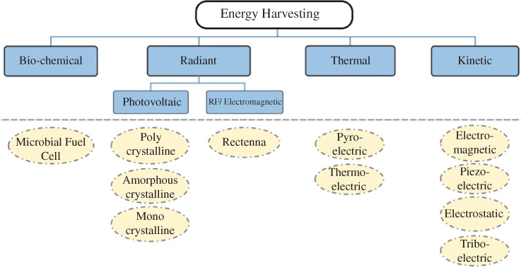
Figure 12.4 Energy sources (rectangular blocks) and their extraction techniques (oval blocks) [14].
Source: Courtesy of Anwar Bhatti, N., Alizai, M.H., Syed, A.A. and Mottola, L.
12.6.1 Harvesting Energy from Kinetic Sources
Kinetic energy is generated by motion. It is one of the most fundamental forces of nature and is described as the work required to accelerate a body of a given mass from rest to a certain speed. The body gains the energy during its acceleration and maintains this amount of energy unless its speed changes. The same amount of work is performed by the body when decelerating to a state of rest. Beyond the computing domain, leveraging kinetic energy to power various devices is an established practice. One example is that of self-winding watches, where the mainspring is wound automatically as a result of the natural motion of one's arm.
Kinetic energy may take numerous forms. In the following, popular forms of kinetic energy together with the corresponding most commonly employed extraction techniques are discussed. These, however, should not be understood as mutually exclusive categories. A given form of kinetic energy may, for example, easily transform into a different one. As a result, extraction techniques employed for one form of kinetic energy are sometimes applicable when kinetic energy manifests in different ways.
One of the most common kinetic energy types is produced by vibration. Vibrations from manufacturing machines, mechanical stress, and sound waves are popular sources of kinetic energy. The vibration mechanical energy may be described using a simple mass-spring model. Assume there is a mass of m connected to a spring of factor k. There is also a damper with a damping parameter of b, as illustrated in Figure 12.5. The entire device moves relative to the inertial frame with the position of the case at time instant t described by u(t). The displacement x(t) can be derived by solving the following second-order differential equation:
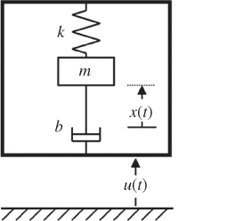
Figure 12.5 A translational inertial generator model using mass, spring, and damper.
Assuming that the device vibration relative to the inertial frame is defined as u (t) = sin(ωt) then the steady state solution for x(t) is:
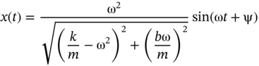
In that case the total power dissipated in the damping element is [15]:
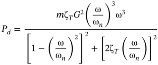
where the natural frequency of the spring is ![]() and the damping factor is ζT = b/(2mωn). For a given amplitude of acceleration, A, the amplitude of the displacement decreases as G = A/ω2. The peak power happens when ω = ωn, resulting in:
and the damping factor is ζT = b/(2mωn). For a given amplitude of acceleration, A, the amplitude of the displacement decreases as G = A/ω2. The peak power happens when ω = ωn, resulting in:
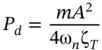
This shows the relationship between the total power and the system parameters. Any parasitic element in the system can, however, affect or reduce this power.
Piezoelectric [4], electromagnetic, or electrostatic effects [16, 17] are the most important basis of kinetic energy measurement. As shown in Figure 12.6, these solutions share the fundamental mechanism of converting vibrations into electric energy. Two involved subsystems are the mass-spring system and a mechanical-to-electrical converter. The mass-spring system transforms vibrations into motion between two elements relative to a single axis. The mechanical-to-electrical converter transforms the relative motion into electric energy by exploiting any of the three aforementioned effects.
Solutions exploiting piezoelectric effect are based on a property of some crystals that generate an electric potential when they are twisted, distorted, or compressed [18]. When a piezoelectric material is under some external force, it causes a deformation of the internal molecular structure that shifts positive and negative charge centres. This produces a macroscopic polarisation of the material directly proportional to the applied force. The resulting potential difference across the material generates an alternating current (AC) which is then converted into a direct current (DC).
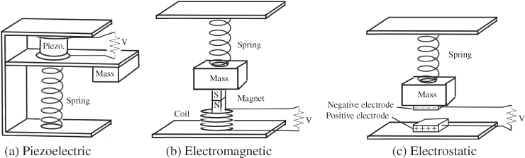
Figure 12.6 Simplified models of different vibration energy harvesters [14].
Source: Courtesy of Anwar Bhatti, N., Alizai, M.H., Syed, A.A., and Mottola, L.
Although piezoelectric materials are not necessarily used for harvesting energy from vibrations [19, 20], they are most often employed with a cantilever-like structure, as illustrated in Figure 12.6a. The cantilever acts as the mass-spring system. When the beam bends due to vibrations, it creates stress on the piezoelectric film, generating AC. The cantilever's resonant frequency is a key factor in determining the efficiency and can be adjusted by changing the mass at the end of the beam and the material. Owing to their mode of operation, these systems capture not only the periodic ambient vibrations but also sudden or sporadic motion. The overall efficiency of a piezo element clamped to a substrate and cyclically compressed at its resonant frequency is [21]:

where k is the electromechanical coupling coefficient, and Q is the quality factor of the resonator. As Q becomes larger, the efficiency tends towards unity but for typically achievable Q factors the efficiency increases significantly for higher values of k.
The electromagnetic effect is ruled by Faraday's and Lenz's laws, stating that a change in the magnetic conditions of a coil's surrounding generates an electromotive force. This causes a voltage to be induced in the coil. To make a change in the magnetic conditions around a coil, a magnet acts as the mass in a mass-spring system that produces movement parallel to the coils axis [22, 23]. This concept can be seen in Figure 12.6b. This is not the only way to exploit the electromagnetic effect. For example, DeBruin et al. [24] have developed a current sensor that leverages the changes in the magnetic field induced by an AC current line. This, in turn, induces an AC signal on the secondary coil, producing sufficient energy to power the sensor device.
In the case of mass-spring systems, besides the magnet's mass, its material and the coils characteristics are used to determine the efficiency of the harvesting device. Most solutions use neodymium iron boron (NdFeB) for the magnet, as it provides the highest magnetic field density. The number of turns and the material used for the coil help tune the resonant frequency according to the expected ambient vibrations. Although electromagnetic generators are more efficient than piezoelectric ones, their fabrication at the micro level is difficult as it involves a complex assembly and care must be taken to align the magnet with the coil. These aspects negatively impact the overall system robustness.
Electrostatic transducers, on the other hand, produce electric energy due to the relative motion of two capacitor plates, as shown in Figure 12.6c. When the ambient vibration is imposed on a variable capacitance structure, its capacitance oscillates between its maximum and minimum values. An increase in the capacitance decreases the voltage and vice versa. If the voltage is constrained, the charges start flowing towards a storage device, converting the vibration energy into electrical energy. Consequently, electrostatic energy harvesters are modelled as current sources [25]. The main benefit of electrostatic transducers over piezoelectric and electromagnetic ones is the small form factor (i.e. they can be highly reduced in size), as they can be easily fused into a micro-fabrication process [15]. However, they require an initial charge for the capacitor.
Body movement and possible tremor are among those kinetic sources which can be harvested for BSNs. There are many other sources of kinetic energy with wide applications in WSNs such as wind and water flows used by wind and water turbines.
To extract kinetic energy from human motion, the same techniques employed for vibrations – such as those based on piezoelectric, electromagnetic, and electrostatic effects – are applied. For example, Paradiso and Feldmeier [20] have designed a system able to harvest energy from the push of a button through a piezoelectric material. The device then transmits a digital identifier wirelessly which can be used to control other electronic equipment.
In addition, it is possible to harvest electric energy from movements such as footfalls or finger motion through the triboelectric effect. This is very natural phenomena, which occurs when different materials contact by friction and become electrically charged. Rubbing glass with fur or passing a combing the hairs can, for example, yield triboelectricity. In another energy-harvesting approach using the triboelectric effect Hou et al. [26] showed that a triboelectric energy harvester embedded within a shoe is able to power 30 light-emitting diodes. These devices are typically composed of two films of different polymers laid in a ‘sandwich’ structure, as in Figure 12.7a. The charge is generated by rubbing two polymer films together and then captured by two electrodes.
To capture triboelectric energy generated by the touch of human skin, a single-electrode device is used, as in Figure 12.7b. When a positively charged surface, such as a human finger, comes in contact with the polymer, it induces a negative charge on the polymer. The overall circuit remains neutral as long as the two surfaces remain in contact, producing zero voltage on the load, as indicated on the left-hand side of Figure 12.7b. However, as the positively charged surface moves away, as shown on the right-hand side of Figure 12.7b, the polymer induces a positive charge on the electrode to compensate for the overall charge. This makes the free electrons flow from the polymer towards the electrode and then to the ground, producing output voltage on the load. Once the polymer returns to the original state, the voltage drops back to zero [14].
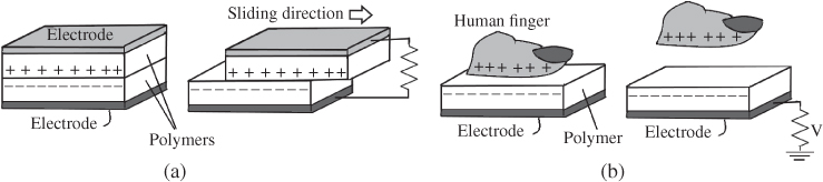
Figure 12.7 Two modes of energy harvesting through the triboelectric effect [14]: (a) double electrode triboelectric and (b) single electrode triboelectric harvesters.
Source: Courtesy of Anwar Bhatti, N., Alizai, M.H., Syed, A.A., and Mottola, L.
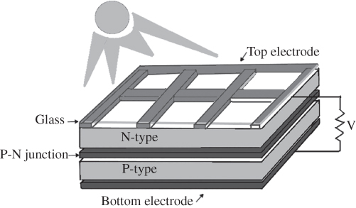
Figure 12.8 Simplified model of a photovoltaic cell [14].
Source: Courtesy of Anwar Bhatti, N., Alizai, M.H., Syed, A.A., and Mottola, L.
12.6.2 Energy Sources from Radiant Sources
Radiant energy is the energy carried by light or electromagnetic radiations. Light, mainly solar light, is the most common form of radiant energy. Radio frequency (RF) and ultrasound are very popular radiant energy sources too.
One common way to extract energy from light is by means of the photoelectric effect for below the infrared spectrum, with solar (visible) light as the primary example. Photovoltaic cells are one of the most mature energy-harvesting devices. From Figure 12.8, a photovoltaic cell, also known as a solar cell, consists of a minimum of two layers of semi-conducting material, mostly silicon. The N-type layer is doped with impurities to increase the concentrations of electrons. Likewise, freely moving positive charges called holes are introduced by doping the silicon of the P-type layer. Each two layers make a P–N junction. When light hits the N-type layer, due to the photoelectric effect, the material absorbs the photons and thus releases the free electrons. The electrons travel through the P–N junction towards the P-type layer to fill the holes in the latter. Among the freed electrons, some do not find a hole in the P-type layer and move back to the N-type layer. This occurs through an external circuit. The produced current is directly proportional to the intensity of light. Thus, photovoltaic cells are generally modelled as current sources [27].
Solar cells are often characterised by the relation between their efficiency against the actual load and operating temperature.
As for the RF energy harvesting, the key element of an RF energy-harvesting device is a special type of antenna called a rectenna. A rectenna comprises a standard antenna and a rectifying circuit making a rectenna look like a voltage-controlled current source [28]. The power levels in the harvested energy for WSNs using rectenna has been reported to be from nW to mW depending on the distance from the nearest base station. Unlike other techniques, the conversion of RF transmissions into electrical current through the rectenna does not involve any mechanical process.
12.6.3 Energy Harvesting from Thermal Sources
Thermal energy refers to the internal energy of an object which follows the thermodynamic equilibrium conditions. Whenever these conditions cease to exist, the resulting matter or energy flows become usable to harvest electric energy through thermoelectric or pyroelectric techniques.
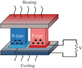
Figure 12.9 Simplified illustration of thermoelectric effect leading to electrical current [14].
Source: Courtesy of Anwar Bhatti, N., Alizai, M.H., Syed, A.A. and Mottola, L.
Deriving energy from a thermal source requires a thermal gradient. The efficiency of conversion from a thermal source follows the Carnot efficiency as:
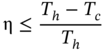
where Th is the absolute temperature on the ‘hot’ side of the device and Tc is the absolute temperature on the ‘cold’ side. Therefore, the greater the temperature difference, the greater the efficiency of the energy conversion.
Thermoelectric techniques are based on Seebeck's effect, which is conceptually the same as the photovoltaic techniques described in Section 12.6.2. As an example, in Figure 12.9, as the temperature difference between opposite segments of the materials increases, the charges are driven towards the cold end. This creates a voltage difference proportional to the temperature difference across the base electrodes. Thus, the thermoelectric harvesters can be modelled as voltage sources [27]. Silicon wafers or aluminium oxides are typically used as the substrate material due to their high thermal conductivity.
In contrast, pyroelectric energy harvesters use materials with the ability to generate a temporary voltage as their temperature is made continuously varying, much like piezoelectric materials generate a potential when they are distorted. Specifically, temperature changes cause the atoms to reposition themselves in a crystalline structure, changing the polarisation of the material. This induces a voltage difference across the crystal, which gradually disappears due to leakage currents if the temperature stays constant.
Since the thermal sources have no moving parts, they are more robust to environmental effects compared with other micro-level harvesters. The devices may thus achieve operational lifetimes of several years without maintenance. Because of their mode of operation, it is also relatively simple to achieve small form factors. Both thermoelectric- and pyroelectric-based harvesters are becoming widely available in the market. The application of these harvesters is suitable for BAN applications as the body heat can be utilised.
12.6.4 Energy Harvesting from Biochemical and Chemical Sources
Energy may be harvested from biological or chemical processes. Among biochemical extraction techniques, microbial fuel cells (MFC) use biological waste to generate electrical energy. As schematically shown in Figure 12.10, bacteria in water metabolise biological waste by breaking it down in an oxidisation process. This results in the creation of free electrons along with CO2 and H+ ions. If the environment has oxygen deficiency then an anode picks up the free electrons and transports them to a corresponding cathode where, in an environment abundant in oxygen, the reduction process completes, yielding a water molecule.
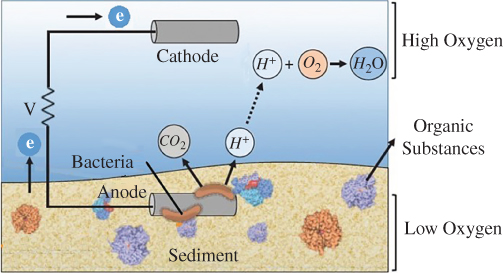
Figure 12.10 Microbial fuel cell concept: bacteria remove electrons from organic material; the electrons flow through an anode–cathode, battery-like, structure where the two compartments are located in mediums with different O2 concentration [14].
Source: Courtesy of Anwar Bhatti, N., Alizai, M.H., Syed, A.A., and Mottola, L.
(See color plate section for color representation of this figure)
On the other hand, methane is a widely available abundant energy source used for power generation in thermal power plants via combustion, but direct conversion to electricity in fuel cells is challenging. Using recent technology, a microbial fuel cell has been demonstrated to efficiently convert methane directly to current by careful selection of a consortium of microorganisms [29].
The efficiency of an MFC is therefore dependent on the difference in oxygen concentration across the anode and the cathode tubes. This is why, for example, MFCs deployed in marine environments have the anode partly embedded in soil and the cathode placed close to the surface, at a higher oxygen concentration, as in Figure 12.10. MFCs are thus modelled as a voltage source in series with a resistance. They are robust and require little maintenance as long as the renewable resource, such as biological waste, is available. Recent results also indicate the potential to harvest energy from voltage differences across the xylem of a tree bark and the soil [30] following similar principles.
For miniaturised devices, such as biomedical implants, enzymatic biofuel cells are also considered [31]. Enzymes are proteins generated by living organisms to catalyse chemical reactions. Unlike MFCs, enzymatic biofuel cells do not use living organisms to trigger the oxidation process but only some of the enzymes produced by specific microorganisms, which are carefully extracted and purified for use. This results in higher energy efficiency compared with the MFCs, at the expense of higher production costs [32]. Moreover, the power densities of enzymatic biofuel cells vary significantly compared to MFCs, as they are typically several times smaller [33].
Extraction techniques based on chemical processes typically exploit and result from corrosion phenomena. The two main factors responsible for the corrosion of steel are carbonation and oxidation under the presence of water. The water may be in touch with the iron or seeps through cement pores or other surrounding materials. These elements, when reacting with iron (Fe), form new compounds like hydrated iron oxides (Fe2O3nH2O) or iron oxide-hydroxide, FeO(OH), also known as rust, while releasing electrons. The portion of steel that releases electrons acts as an anode, whereas the portion of metal that accepts the electrons acts as a cathode, with water acting as an electrolyte. The resulting flow of electrons is harvested in the form of electrical current.
Table 12.2 Properties of energy-harvesting sources. Taken from [34] and [35].
| Energy harvesting sources | |||||||
| Property | Biochemical | Visible light | RF waves | Thermal | Vibration | Air/Water flow | Human/Animal motion |
| Power density | Low (∼300 μW) | Low (180 μW) to high (240 mW) | Low (∼100 μW) | Low (218 μW to 250 μW) | Low (70 μW) to medium (12 mW) | Medium (7.7 mW to 18 mW) | Medium (∼1 mW) |
| Conversion efficiency | N/A | ∼0.1% to 15% | ∼33% | ∼0.1% to 10% | N/A | N/A | ∼7.5% to 11% |
| Form factor | Large | Small | Medium | Small | Small | Large | Small |
| Robustness | High | High | High | High | Low | Low | Low |
| Cost | Medium | Low | Medium | Low | Low | High | Low |
Source: Courtesy of Vullers, R.J. M., van Schaijk, R., Doms, I., Van Hoof, C., and Mertens, R.
Table 12.2 summarises the practical properties of various energy-harvesting sources and approaches. Although the majority of these sources are used in WSN, a number of them are applicable to BSNs too. Energy from body motion, light, and heat are among the very obvious ones.
12.7 Topology Control
A popular method to increase energy efficiency in WSNs is by employing topology control algorithms. There are some works, though limited, in topology control. The important one is by Tan et al., who presented a game-theory-based distributed energy harvesting aware (EHA) algorithm [36], which models the behaviours of sensor nodes as a game. This work analyses the energy consumption rate and energy-harvesting rate of each node at different time instants. In this game, the high harvesting power nodes cooperate with the low harvesting power nodes to maintain the connectivity of the network. The algorithm first constructs a preliminary topology based on the directed local spanning sub-graph (DLSS) algorithm [37]. Then, each node k tries to find a neighbour that covers the farthest neighbour of node k by adjusting the transmission power step by step. The idea is that a node may make a sacrifice by increasing its transmission power if it can help reduce energy consumption at another node with lower residual energy.
These algorithms focus only on the transmission power while constructing a static topology without taking into account the residual energy of the nodes, so, they may not be effective when the nodes have different energy levels and when the number of active nodes varies with time in EH-WSN. Since the number of operational nodes in EH-WSNs is varying, there is no possibility of having a centralised solution. Therefore, Wang et al. [38] suggest two localised energy-based topology control algorithms, namely EBTC-1 and EBTC-2, to alleviate the above shortcomings.
The basic idea of EBTC-x (x = 1, 2) is that the topology control in EH-WSN is not just about selecting links with low costs but also includes selecting neighbours according to various energy levels of the nodes. It is therefore aimed to design greedy algorithms to maximise the remaining nodes' energy and select neighbours with high residual energy. Consequently, since the nodes have ‘high energy neighbours’, their neighbours can receive and transmit more information, resulting in a more sustainable network. Both variants consist of two phases: topology construction and topology maintenance. The key idea in the construction phase is that the nodes select their neighbours according to the distances to the neighbours and the remaining energy of its neighbours. The nodes first collect their neighbour information, including the remaining energy and the distances between nodes. Then, each node selects neighbours according to a metric based on local information. Finally, the nodes adjust their transmission power to the lowest value that is needed to reach the farthest neighbours. In this case, the distance is no longer the only factor in selecting the neighbours. Topology maintenance is required in EH-WSN as a mechanism to update the topology whenever the nodes leave or rejoin the network, taking care of the nodes' energy in the heterogeneous network and keeping all active nodes in the topology.
There are two major differences between EBTC-1 and EBTC-2: first of all, they use different strategies to trigger nodes to initialize the neighbour information collection process and, second, the nodes select neighbours based on different criteria.
EBTC-1 is for converge cast applications of WSNs (where unlike broadcast the data from different nodes are sent and combined in a sink node) and EBTC-2 is for a generic scenario where all the nodes are required to be strictly connected. In some cases, to ensure fault tolerance, the network may be required to be k-connected. While typical topology control algorithms select a particular number of neighbours, the distinguishing feature of both these algorithms is that they select neighbours based on energy-levels and render the global topology strongly connected. It has been shown by simulation that EBTC-1 and EBTC-2 reduce the transmission power and let nodes have neighbours with high remaining energy [38]. It has been claimed that using these algorithms the remaining energy per neighbour is increased by approximately 33%. In addition, in terms of energy consumption and fault tolerance, the algorithms typically achieve significantly less energy compared to K-Neigh [38]. In the K-Neigh algorithm the k neighbours of each node are selected based on distance. Using the algorithm, it is possible for a node to estimate the distance to another node by going through the following steps [38]:
- Every node broadcasts its ID at maximum transmit power.
- Upon receiving the broadcast messages from other nodes, every node stores the neighbour information.
- Every node computes its k-closest neighbours, and broadcasts this information at maximum transmit power.
- By exchanging neighbour information, the nodes are able to have lists of symmetric neighbours.
At the end of protocol execution, the nodes set the transmit power to the minimum value needed to reach the farthest node in the neighbour lists. In this approach, however, the connectivity of the k-neighbour graph should be guaranteed.
12.8 Typical Energy Harvesters for BSNs
As mentioned above, motion, thermal, and light are the most popular energy sources in a BSN. The early and most intuitive method of scavenging energy from footsteps utilised piezoelectric materials embedded in areas of footwear that experience the most strain. The method has been used for a long time to light up baby shoes when they walk around. In such cosmetic methods, the energy is intermittently generated but not harvested. Shenck and Paradiso demonstrated a method of harnessing foot-strike energy using piezoelectric by inserting a piezoelectric transducer (PZT) foil into the heel area of a shoe [39]. For their energy-harvesting device an average power of 8.4 mW was reported at a foot strike frequency of 0.9 Hz. The benefit of such a design is its unobtrusiveness with respect to the user's ergonomic experience with the product. However, the magnitude of energy that can be harvested is limited by the use of piezoelectric devices which rely on mechanical strain enforced by the heel inside the shoe to create a potential difference. Moro et al. also designed a shoe for energy harvesting with a piezoelectric vibrating cantilever device [40], where the generated power was limited by the low frequency of foot strike.
Akay et al. designed an energy-harvesting system installed in the boot for satellite positioning [41]. Their system converts able-bodied bipedal locomotion to usable electricity by way of unobtrusive hardware installed in footwear. This generates airflow from the compressive forces applied by feet inside shoes during walking [42]. The structure of this energy-harvesting system is displayed in Figure 12.11. Air bulbs are positioned in the sole, optimised relative to the length of the foot. Outflow from the bulbs is directed towards a two-stage turbine enclosure that drives two DC motors in series to generate electrical power. This energy is stored in a supercapacitor and used to charge a battery that powers a global positioning system (GPS) receiver. The key design parameters considered for the air bulbs are their effective stiffness and time period of regaining original shape after being compressed.
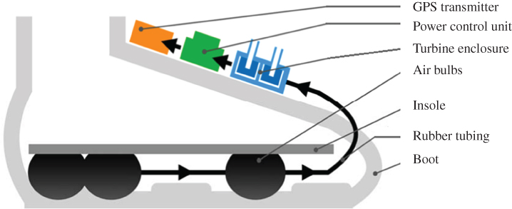
Figure 12.11 The structure of boot-installed energy harvesting system [42].
Source: Courtesy of Akay, H., Xu, R., Han, D.C.X., Teo, T.H., and Kim, S.-G.
12.9 Predicting Availability of Energy
The effective use of energy-harvesting technologies needs to deal with the variable behaviour of the energy sources, which governs the amount and rate of harvested energy over time. In the case of predictable, noncontrollable power sources, such as the solar one, energy prediction methods can be used to forecast the source availability and estimate the expected energy intake [40–42]. Such a predictor can alleviate the problem of harvested power being neither constant nor continuous, allowing the system to take critical decisions about the utilisation of available energy. For prediction of solar and wind harvesters some methods have been proposed [43, 44].
In general, the idea is to develop models that can predict the measurements of a sensor given a subset of others and then use these prediction models to reduce the number of sensors or select a subset of sensors for taking the measurements in any particular time interval.
Kansal et al. [45] proposed a solar energy prediction model based on an exponentially weighted moving-average (EWMA) filter [46]. This method is based on the assumption that the energy available at a given time of the day is similar to that available at the same time of previous days. The time series is segmented into N time slots of fixed length (usually 30 minutes each). The amount of energy available in previous days is maintained as a weighted average where the contribution of older data is exponentially decreasing. The EWMA model uses a smoothing factor 0 ≤ α ≤ 1 to predict that in time slot n the amount of energy in day d ![]() is available for harvesting, where xn is the amount of energy harvested by the end of nth slot.
is available for harvesting, where xn is the amount of energy harvested by the end of nth slot.
Another prediction method, called weather-conditioned moving average (WCMA), was proposed by Piorno et al. [47] for alleviating the EWMA shortcomings. Similar to EWMA, WCMA takes into account the energy harvested in the previous days. However, it also considers the weather conditions of the current and previous days. Specifically, WCMA stores a matrix E of size D × N, where D is the number of days considered and N is the number of time slots per day. The entry Ed,n stores the energy harvested in day d at time slot n. Energy in the current day is kept in a vector C of size N. In addition, WCMA keeps a vector M of size N whose nth entry Mn stores the average energy observed during time slot n in the last D days:
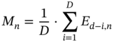
At the end of each day Mn is updated with the energy just observed, overwriting the date of the previous day. The amount of energy Pn+1 predicted by WCMA for the next time slot n + 1 of the current day is estimated as Pn + 1 = α · Cn + (1 − α) · Mn + 1 · ρn, where Cn is the amount of energy observed during time slot n of the current day, Mn+1 is the average harvested energy during time slot n + 1 over the last D days, and ρn is a weighting factor providing an indication of the changing weather conditions during time slot n of the current day with respect to the previous D days.
Another algorithm, developed in Eidgenössische Technische Hochschule (ETH), aka the ETH algorithm, combines information about the energy harvested during the current time interval with the energy availability obtained in the past [48]. Similar to EWMA, the contribution of older data is exponentially decreasing with the past-to-now time interval. These algorithms have been further modified to enhance the prediction performances with minor differences in the outcome.
12.10 Reliability of Energy Storage
Energy-harvesting-enabled sensor networks not only have ultra-low power constraints but also should cope with the time-varying state of available energy. This means the energy stored at the energy buffer is constantly increasing and decreasing in a random manner. In addition to this, the ambient energy has a slow temporal dynamic which modulates the harvesting power in several orders of magnitude. The self-powered WSN approach aims to extend the sensor node life by means of energy harvesting. However, the low power density that these energy sources provide compared to the required energy for the communication process creates the necessity of temporal storage. Unfortunately, the random nature of the power sources implies that the energy storage unit might not be able to guarantee the communication at all times, thus giving a certain loss probability, which is a function of the statistics of the harvesting process and the energy storage capacity [49, 50]. A typical solution to reduce this loss probability is an over-dimensioning of the energy storage capacity, which implies a very large overhead in both volume and weight.
As an example, the available power of solar energy ranges from 10 μW cm−2 to as high as 100 μW cm−2 a day [51]. Often it is challenging for the network designer to dimension critical parameters such as the link capacity [52], the energy buffer capacity of each sensor node, or to design transmission policies [53]. Among other critical parameters, the energy buffer which is usually composed of supercapacitors or chargeable batteries is an expensive and larger volume subsystem. In particular, a typical supercapacitor requires an approximated volume of 2 cm in order to store 1 J of energy [9–11, 45, 54–56]. Thus, the design of the energy buffer might result either in an over-dimensioning of its maximum capacity which leads to significant downscaling impairments and an increase in cost or, on the contrary, an under-dimensioning, which would lead to unnecessary interruptions along the normal operation of the network. In order to capture the random patterns of the energy-harvesting process, the systems presented in [52] and [55] model the energy source as an uncorrelated process in the communications timescale, thus the model can handle specific communication patterns. As a result, these models show that very low buffer capacity (i.e. just a few tens of times the energy of a single data packet) is enough to maintain the communication. On the other hand, those suggested in [45, 51, 56] are aimed for solar energy harvesting and account for daily temporal variations. In this case, these models cannot provide detailed information regarding the communication energy harvesting random patterns, but point out to energy buffer of thousands to even millions of times larger than the energy of a single data packet.
Cid-Fuentes et al. [49] suggested a scalable energy model for estimation of the loss probability and applied their model in order to introduce some guidelines for battery dimensioning. They also provided a general-purpose framework for dimensioning the energy buffer [50]. They presented a dynamics-decoupled multisource-capable energy model to handle fast random patterns of communications and energy harvesting, while capturing slow variations of the ambient energy in both time and space. In their model they assume that the energy field is given by adding two separated dynamics:
where p(r, t) is a dimension-less spatiotemporally uncorrelated fast dynamic random process and PS(r, t), in power units, stands for a spatiotemporally slow varying random process.
The model can more accurately evaluate the sensor node performance in terms of the energy storage capacity and estimation of the expected energy of the neighbouring nodes. The model based on energy-Erlang provides a link between the energy model, the environmental harvested power, and the energy buffer.
The above proposed source-versatile, dynamics-decoupled framework more accurately models the node energy-harvesting process and shows how the energy buffer helps to counteract the impact of harvested energy temporal evolution upon the energy outage probability, thus showing a strong compromise between performance and size.
12.11 Conclusions
Energy harvesting is now an essential integral part of sensor networks as the sensors may not have direct or indirect connections to the conventional energy suppliers. Energy from the environment and the environmental changes and processes have attracted much attention, particularly in WSNs, which are mostly used for wireless communications. For BSNs often smaller sensors are used in order to alleviate the discomfort of wearing intrusive devices. Therefore, more natural energy sources, suitable for various environments and activities are promoted for energy harvesting. Motion, vibration, thermal, and radiation (mostly visible light) are among the most desirable ones. Research has to be carried out to facilitate energy transfer among the nodes (sensors) as well as their efficiency in terms of power, size, and price. The major challenges in energy harvesting are the provision of the required energy to the sensor network and ensuring that sufficiently reliable energy storage is in place for continuous communication between the nodes in a sensor network. More advanced research may include a full topology control of the network to ensure the limited harvested energy is fairly and evenly distributed among the sensors. Moreover, in a decentralised distributed system with smart sensors, it is favourable to enable prediction of the power availability and limitations for each sensor by its neighbouring sensors.
References
- 1 Crossbow Products. (2008). MiCAz: Wireless measurement system. http://www.openautomation.net/uploadsproductos/micaz_datasheet.pdf (accessed 13 January 2020).
- 2 Crossbow Products. (2008). Imote2: high-performance wireless sensor network node. http://wsn.cse.wustl.edu/images/e/e3/Imote2_Datasheet.pdf (accessed 13 January 2020).
- 3 Jennic Ltd. 2008. JN5139 Wireless Microcontroller (IEEE 802.15.4 and ZigBee). https://fccid.io/TYOJN5139M0/User-Manual/Module-data-sheet-773710 (accessed 13 January 2020).
- 4 Mathna, C., Donnell, T.O., Martinez, R.V. et al. (2008). Energy scavenging for long – term deployable wireless sensor networks. Talanta 75 (3): 613–623.
- 5 Seah, W.K.G., Tan, Y.K., and Chan, A.T.S. (2013). Research in energy harvesting wireless sensor networks and the challenges ahead. Autonomous Sensor Networks: 73–93.
- 6 Kansal, A., Hsu, J., Zahedi, S., and Srivastava, M.B. (2007). Power management in energy harvesting sensor networks. ACM Transactions on Embedded Computing Systems (TECS) – Special Section LCTES'05 6 (4): 1–38.
- 7 Wind Data. (2001). Wind and radiation data. http://www.esrl.noaa.gov/psd/data/gridded/reanalysis/ (accessed 13 January 2020).
- 8 Vijayaraghavan, K. and Rajamani, R. (2007). Active control based energy harvesting for battery-less wireless traffic sensors: theory and experiments. In: Proceedings of American Control Conference, New York, USA (11–13 July 2007), 4579–4584. IEEE.
- 9 Sanei, S., Monajemi, S., Rastegarnia, A. et al. (2018). Multitask cooperative networks and their diverse applications. In: Learning Approaches in Signal Processing (eds. W.-C. Siu, L.-P. Chau, L. Wang and T. Tan). Jenny Stanford Publishing.
- 10 Vahidpour, V., Rastegarnia, A., Khalili, A., and Sanei, S. (2019). Partial diffusion Kalman filtering for distributed state estimation in multi-agent networks. IEEE Transactions on Neural Networks and Learning Systems https://doi.org/10.1109/TNNLS.2019.2899052.
- 11 Sayed, A.H. (2014). Adaptation, learning, and optimization over networks. Foundations and Trends in Machine Learning 7 (4–5): 311–801.
- 12 Stojcev, M.K., Kosanovic, M.R., and Golubovic, L.R. (2009). Power management and energy harvesting techniques for wireless sensor nodes. In: 2009 9th International Conference on Telecommunication in Modern Satellite, Cable, and Broadcasting Services, 65–72. IEEE.
- 13 Paulo, J. and Gaspar, P.D. (2010). Review and future trend of energy harvesting methods for portable medical devices. In: Proceedings of the World Congress on Engineering, London, UK (30 June–2 July 2010), 909–914. WCE.
- 14 Anwar Bhatti, N., Alizai, M.H., Syed, A.A., and Mottola, L. (2016). Energy harvesting and wireless transfer in sensor network applications: concepts and experiences. ACM Transactions on Sensor Networks (TOSN) 12 (3): 1–40.
- 15 Roundy, S., Wright, P.K., and Rabaey, J. (2003). A study of low level vibrations as a power source for wireless sensor nodes. Computer Communications 26 (11): 1131–1144.
- 16 Carlos, A. and de Queiroz, M. (2013). Electrostatic generators for vibrational energy harvesting. In: IEEE Fourth Latin American Symposium on Circuits and Systems (LASCAS), Cusco, Peru (27 February–March 2013), 1–4. IEEE.
- 17 Chye, W.C., Dahari, Z., Sidek, O., and Miskam, M.A. (2010). Electromagnetic micro power generator: a comprehensive survey. In: IEEE Symposium on Industrial Electronics Applications (ISIEA), Penang, Malaysia (3–6 October 2010), 376–382. IEEE.
- 18 Poulin, G., Sarraute, E., and Costa, F. (2004). Generation of electrical energy for portable devices: comparative study of an electromagnetic and a piezoelectric system. Sensors and Actuators A: Physical 116 (3): 461–471.
- 19 Zhu, D., Beeby, S.P., Tudor, M.J. et al. (2013). Novel miniature airflow energy harvester for wireless sensing applications in buildings. IEEE Sensors Journal 13 (2): 691–700.
- 20 Paradiso, J.A. and Feldmeier, M. (2001). A compact, wireless, self-powered pushbutton controller. In: Proceedings of the 3rd International Conference on Ubiquitous Computing, 299–304. Springer.
- 21 Beeby, S.P., Tudor, M.J., and White, N.M. (2006). Review paper: energy harvesting vibration sources for microsystems applications. Measurement Science and Technology 17 (12): 175–195.
- 22 Kulah, H. and Najafi, K. (2004). An electromagnetic micro power generator for low-frequency environmental vibrations. In: 17th IEEE International Conference on Micro Electro Mechanical Systems, Maastricht, Netherlands (25–29 January 2004), 237–240. IEEE.
- 23 Mizunoand, M. and Chetwynd, D.G. (2003). Investigation of a resonance microgenerator. Journal of Micromechanics and Microengineering 13 (2): 209–216.
- 24 DeBruin, S., Campbell, B., and Dutta, P. (2013). Monjolo: An energy-harvesting energy meter architecture. In: Proceedings of the 11th ACM Conference on Embedded Networked Sensor Systems. SenSys'13. ACM https://www.cs.virginia.edu/∼bjc8c/papers/debruin13monjolo.pdf, accessed 14 December 2019.
- 25 Torres, E.O. and Rincon-Mora, G.A. (2006). Electrostatic energy harvester and Li-ion charger circuit for micro-scale applications. In: Proceedings of the 49th IEEE International Midwest Symposium on Circuits and Systems (MWSCAS), 65–69. IEEE.
- 26 Hou, T.-C., Yang, Y., Zhang, H. et al. (2013). Triboelectric nanogenerator built inside shoe insole for harvesting walking energy. Nano Energy 2 (5): 856–862.
- 27 Kang, K. (2012) Multi-source energy harvesting for wireless sensor nodes. Royal Institute of Technology (KTH). https://pdfs.semanticscholar.org/939c/cef633c4c076ffc7b6ab44e6c6ac4c74684a.pdf, accessed 14 December 2019.
- 28 Nimo, A., Beckedahl, T., Ostertag, T., and Reindl, L. (2015). Analysis of passive RF-DC power rectification and harvesting wireless RF energy for micro-watt sensors. AIMS Energy 3 (2): 184–200.
- 29 Zhiyong, J.R. (2017). Microbial fuel cells: running on gas. Nature Energy 2 (6): 17093.
- 30 Love, C.J., Zhang, S., and Mershin, A. (2008). Source of sustained voltage difference between the xylem of a potted Ficus benjamina tree and its soil. PLoS One 3 (8): e2963.
- 31 MacVittie, K., Halamek, J., Halamkova, L. et al. (2013). From “cyborg” lobsters to a pacemaker powered by implantable biofuel cells. Energy and Environmental Science 6: 81–86.
- 32 Armstrong, R.E. (2010). Bio-Inspired Innovation and National Security. Smashbooks.
- 33 Barton, S.C., Gallaway, J., and Atanassov, P. (2004). Enzymatic biofuel cells for implantable and microscale devices. Chemical Reviews 104 (10): 4867–4886.
- 34 Vullers, R.J.M., van Schaijk, R., Doms, I. et al. (2009). Micropower energy harvesting. Solid-State Electronics 53 (7): 684–693.
- 35 Sudevalayam, S. and Kulkarni, P. (2011). Energy harvesting sensor nodes: survey and implications. IEEE Communications Surveys & Tutorials 13 (3): 443–461.
- 36 Tan, Q., An, W., Han, Y. et al. (2015). Energy harvesting aware topology control with power adaptation in wireless sensor networks. Ad Hoc Networks 27: 44–56.
- 37 Li, N. and Hou, J.C. (2005). Localized topology control algorithms for heterogeneous wireless networks. IEEE/ACM Transactions on Networking (TON) 13 (6): 1313–1324.
- 38 Wang, X., Rao, V.S., Prasad, R.V., and Niemegeers, I. (2016). Choose wisely: topology control in energy-harvesting wireless sensor networks. In: 2016 13th IEEE Annual Consumer Communications & Networking Conference (CCNC), 1054–1059. IEEE.
- 39 Shenck, N.S. and Paradiso, J.A. (2001). Energy scavenging with shoe-mounted piezoelectrics. IEEE Micro 21 (3): 30–42.
- 40 Moro, L. and Benasciutti, D. (2010). Harvested power and sensitivity analysis of vibrating shoe-mounted piezoelectric cantilevers. Smart Materials and Structures 19 (11).
- 41 Akay, H., Xu, R., Seto, K., and Kim, S.-G (2017) Energy harvesting footwear. U.S. Patent No. 62/449208, filed 23 October 2017 and issued 26 July 2018.
- 42 Akay, H., Xu, R., Han, D.C.X. et al. (2018). Energy harvesting combat boot for satellite positioning. Micromechanics 9 (5): 1–11.
- 43 Kosunalp, S. (2017). An energy prediction algorithm for wind-powered wireless sensor networks with energy harvesting. Energy 139: 1275–1280.
- 44 Kim, S.-G., Jung, J.-Y., and Sim, M.K. (2019). A two-step approach to solar power generation prediction based on weather data using machine learning. Sustainability 11 (1–16): 1501.
- 45 Kansal, A., Hsu, J., Zahedi, S., and Srivastava, M.B. (2007). Power management in energy harvesting sensor networks. ACM Transactions in Embedded Computing Systems 6 (4): 32–38.
- 46 Cox, D.R. (1961). Prediction by exponentially weighted moving averages and related methods. Journal of the Royal Statistical Society. Series B (Methodological) 23 (2): 414–422.
- 47 Recas Piorno, J., Bergonzini, C., Atienza, D., and Simunic Rosing, T. (2009). Prediction and management in energy harvested wireless sensor nodes. In: 1st International Conference on Wireless Communication, Vehicular Technology, Information Theory and Aerospace & Electronic Systems Technology. Aalborg, Denmark (19 May 2009), 6–10. IEEE.
- 48 Moser, C., Thiele, L., Brunelli, D., and Benini, L. (2007). Adaptive power management in energy harvesting systems. In: Proceedings of 2007 Design, Automation & Test in Europe Conference & Exhibition (DATE), 1–6. IEEE.
- 49 Cid-Fuentes, R.G., Cabellos-Aparicio, A., and Alarcon, E. (2012). Energy harvesting enabled wireless sensor networks: energy model and battery dimensioning. In: BodyNets '12 Proceedings of the 7th International Conference on Body Area Networks, 131–134. ACM.
- 50 Cid-Fuentes, R.G., Cabellos-Aparicio, A., and Alarcon, E. (2014). Energy buffer dimensioning through energy-Erlangs in spatio-temporal-correlated energy-harvesting-enabled wireless sensor networks. IEEE Journal on Emerging and Selected Topics in Circuits and Systems 4 (3): 301–312.
- 51 Gorlatova, M., Wallwater, A., and Zussman, G. (2011). Networking low-power energy harvesting devices: measurements and algorithms. In: Proceedings of the IEEE INFOCOM, 1602–1610. IEEE.
- 52 Rajesh, R., Sharma, V., and Viswanath, P. (2011). Information capacity of energy harvesting sensor nodes. In: Proceedings of the IEEE International Symposium on Information Theory, Saint Petersburg, Russia (31 July–5 August 2011), 2363–2367. IEEE.
- 53 Ozel, O., Tutuncuoglu, K., Yang, J. et al. (2011). Transmission with energy harvesting nodes in fading wireless channels: optimal policies. IEEE Journal on Selected Areas in Communications 29 (8): 1732–1743.
- 54 Pech, D., Brunet, M., Durou, H. et al. (2010). Ultrahigh-power micrometre-sized supercapacitors based on onion-like carbon. Nature Nano 5 (9): 651–654.
- 55 Jornet, J. and Akyildiz, I. (2012). Joint energy harvesting and communication analysis for perpetual wireless nanosensor networks in the terahertz band. IEEE Transactions on Nanotechnology 11 (3): 570–580.
- 56 Susu, A., Acquaviva, A., Atienza, D., and De Micheli, G. (2008). Stochastic modeling and analysis for environmentally powered wireless sensor nodes. In: Proceedings of the 6th International Symposium on Modeling and Optimization in Mobile, Ad Hoc, and Wireless Networks and Workshops. Berlin, Germany (1–3 April 2008), 125–134. IEEE.