6. Building a Media Center System
We admit it. We’re audio/video Luddites. When the receiver in our 15-year-old home audio system failed a few years ago, we didn’t bother to replace it. We have a Panasonic 27” analog television, basic $10/month analog cable TV service with only the broadcast channels, and no satellite receiver.
We rent movies and TV series from Netflix, borrow them from the public library or friends, or buy the DVD sets. (As we write this, we’ve just gotten around to renting The Sopranos. It’s new to us.…) We sometimes watch local TV news, sports, and weather in real time, but that’s about it. We’ve even given up watching PBS because of the intrusive begging and increasingly common commercials.
If there’s something we really want to see, we usually just buy the DVD set or wait until it’s available from Netflix. A few times a year, when we don’t want to wait for the DVD release, we record the program on our DVD recorder. The last time we watched a prime-time network television episode live was sometime in the 20th century. We’ve never bothered watching TV online, because the programs available on Hulu and the network websites contain embedded commercials that can’t be skipped. If we can’t watch something without commercials, we simply refuse to watch it.
Gotcha
One problem with depending on DVDs is that DVD releases are unpredictable. For example, we rented and watched season 1 of Crossing Jordan soon after the DVD set was released in 2008. Alas, we then learned that the remaining five seasons haven’t been released on DVD and probably never will be because of music licensing issues. Oh, well.
We had a similar problem with the fine British comedy-drama Cold Feet, starring the delightful Helen Baxendale. After we’d rented and watched the first three series, we realized belatedly that Netflix didn’t have series four and five. We immediately tried to buy those, only to learn that series four and five had never been released for the US market and were unavailable for purchase.
Amazon had one used copy of series four, but in Region 2 format, which is incompatible with our equipment. Arrrggggh. If we weren’t law abiding, we might have installed a good BitTorrent client and visited Pirate Bay.
So, why do we need a media center system? We don’t, at least if you define a media center system as incorporating PVR/DVR (personal/digital video recorder) functions. In fact, we built a very capable PVR/DVR media center system for the first edition of this book. After we verified that everything worked as it should, we found that we never used the system to record programs. We turned it off. It gathered dust, and eventually we salvaged its parts for other systems. There was nothing wrong with that system, mind you. It worked perfectly. We simply had no need for its recording capabilities. For the second edition of this book, we built another capable PVR/DVR media center system, this one with multiple analog and digital tuner cards. Once again, we turned it on, tested it and found it did everything expected of it, and then turned it off when we realized that we weren’t using it.
But there’s much more to a media center system than just recording TV programs. The first sentence of Wikipedia’s HTPC entry is a pretty good working definition:
A Home Theater PC (HTPC) or Media Center is a convergence device that combines a personal computer with a software application that supports video and music playback, and sometimes digital video recorder functionality.
The emphasis is ours. Sometimes, indeed. A couple of years ago, media center systems were all the rage. Best Buy featured several models in every Sunday supplement section. The Dell and HP home pages had media center systems splashed all over them. NewEgg carried a couple of dozen models. Even Sears sold media center systems. And the focus was always on recording TV programs.
Nowadays, things are very different. We searched the Best Buy website for “media center” and “HTPC” and got no results. The Dell site lists no media center systems, and only one third-party add-on box to provide media center functions when coupled to a standard PC. The HP website lists nothing, nor does the NewEgg site. You can still buy dedicated media center systems, but only from “boutique” vendors. What happened?
First and foremost, media center systems were simply much too expensive for what they do, ranging in price from perhaps $800 at the low end up to $2,500 or more. You could accomplish much the same things with a $150 DVD recorder or a $300 TiVo, or you could simply rent a PVR from your satellite or cable TV provider for a few bucks a month. Furthermore, TiVo, DVD recorders, and satellite/cable PVRs are reasonably reliable appliances; ordinarily, they Just Work. Media center PVR systems tended to crash, fail to record scheduled programs, and otherwise fall down on the job.
So, why bother to include a chapter on building a media center system? Because PVR functions were never anything more than a distraction from the real purpose of a media center system: centralizing your home media storage and making your media easy to access from anywhere in your home.
Brian Bilbrey Comments
As long as the TV provider PVR works just fine. My wife Marcia hardly ever watches “live” TV, but has many hours of programming recorded each week that can be easily fast-forwarded through the mercantile segments of each program.
But what if you also want to record television programs? In that case, our best advice is:
- If your television service is delivered by digital cable or satellite and you want PVR functions, rent or purchase a PVR box from your cable or satellite provider. If your cable or satellite receiver provides dual outputs and your television has dual inputs, you can instead use a DVD recorder, with or without a hard drive for extended recording time. Current U.S. law mandates that any television device that includes a tuner must include an ATSC digital tuner, so a DVD recorder may have no tuner, only a digital tuner, or both analog and digital tuners.
- If you have analog cable TV service, you’ll probably be happy with a DVD recorder, but those are becoming increasingly harder to find. Inexpensive cable/satellite PVR boxes are driving them from the market.
- If, like an increasing number of people, you have “cut the cable” and depend on over-the-air DTV, purchase a DVD recorder with an ATSC tuner.
Determining Functional Requirements
For this third iteration, we were determined to design a media center system that fit our actual needs, rather than those of some hypothetical “average” reader. By following our thought process, you should be able to come up with a media center system configuration that fits your needs as well.
We’ve never really needed our media center system to include TV recording functions, and it’s becoming increasingly obvious that many other people don’t, either. So, we’ll design this system to focus on pure media center functions. If we need to record TV programs, we’ll use one of the methods we listed in the previous section, and we’ll assume that you will, too.
Here’s the list of requirements we came up with:
Video output requirements
Obviously, the low resolution of our current 27” analog television severely constrains what we can do with the system. It was about time to replace our old TV anyway, so we checked Costco to see what TVs were selling for nowadays. We were surprised to find that we could buy a pretty reasonable 42” HDTV with full 1080p support for $600, so for design purposes we assumed that would be our media center system display.
HDTV 1080p resolution is actually 1920×1080, so we’ll need to make sure our video adapter can drive the display at that resolution. We’ll also need to verify that the outputs on the media center system match the inputs on the TV, which are HDMI/HDCP times four for video, and SP/DIF digital optical plus stereo in for audio.
Watching DVD videos
We currently watch rental DVDs using a standard Panasonic DVD player, which the media center system will replace. We don’t currently own or rent Blu-ray discs, but we want to make sure that our media center system can be easily upgraded to support Blu-ray in the future.
Rather than handling the physical discs, we want to rip our collection of purchased DVDs to the hard drive so that we can watch any of them just by pointing and clicking. That means we’ll need plenty of disk space. We want sufficient storage for 500+ DVDs. Allowing additional capacity for music and other files means we’ll want perhaps 4 TB of disk space in our media center system.
Watching web videos
We find ourselves spending increasingly more of our viewing time watching web videos on YouTube and similar services. We don’t care about support for iTunes or other copy-protected video download services, but it’s essential that this system make it easy to browse/watch unprotected web videos.
Listening to audio
We’ve already converted our collection of about 1,000 audio CDs to 320 kb/s VBR (variable bitrate) MP3 files, which Barbara listens to using MP3 players in her SUV and at the gym. It makes sense to use the media center system as the central storage location for these audio files, allowing them to be played back locally in the den or remotely on other systems in the house. We’d like the system to index our collection and offer the standard options for playback (full searchability by title/artist/genre, random shuffle, playlists, and so on). When we buy a new CD, we want to be able to pop it into the system and have the system automatically rip it, store it, and index it.
Viewing images
We have thousands of image files taken with our Pentax digital SLRs and stored in RAW (PEF) format. We’d like the system to store and index these files and make them readily searchable, viewable, and editable. It should also make it easy to produce hard copies, either by sending them to our color printer or by uploading them to the Walgreens website, which we use for most of our photo printing.
Video editing/production
Robert shoots a lot of videos for his YouTube channel, TheHomeScientist. Currently, he edits them on his main office system, but it would be nice to be able to do at least preliminary rough-cut editing while kicking back and relaxing on the sofa. Essentially, that means we’ll need a faster processor, more memory, and a faster hard drive than we might otherwise use. We transfer videos from the camcorder to Robert’s main office system, so FireWire support isn’t necessary.
Web browsing
We want instant access to the Web. For example, while we’re watching a DVD, we might want to pause the video and pop up a browser window to look up a cast member in the Internet Movie Database. Or, if we’ve just gotten back from walking the dog, we might want to check our email to see if our VoIP telephone service has emailed us a new voicemail message notification with an encapsulated audio file.
Interface
Our first thought was to use a standard media center “10-foot interface” with large text and icons and a handheld remote control for navigation. Then we realized that with a 42” display running at 1920×1080 resolution, we didn’t need that; we could simply use a standard desktop interface, which will be easily readable at that size and distance. That means we won’t need a handheld remote and receiver for the media center system. Instead, we can just use a wireless keyboard/mouse with sufficient range to reach across the room.
Hardware Design Criteria
With the functional requirements determined, the next step was to establish design criteria for the media center system hardware. Here are the relative priorities we assigned for our media center system.
|
Price |
★★✩✩✩ |
|
Reliability |
★★★✩✩ |
|
Size |
★★✩✩✩ |
|
Noise level |
★★★★✩ |
|
Expandability |
★★✩✩✩ |
|
Processor performance |
★★★✩✩ |
|
Video performance |
★★✩✩✩ |
|
Disk capacity/performance |
★★★✩✩ |
Here’s the breakdown:
Price
Price is a consideration, but only in the sense that we don’t want to waste money. This media center system will be our shared den PC, and we spend a lot of time in the den. Accordingly, we’ll use only first-rate components in this system, and if spending a few extra dollars buys us additional performance, reliability, or functionality, we’ll spend the extra money.
Reliability
Reliability is moderately important for this system, but primarily because this system will run 24/7/365, and we don’t want to have to stop what we’re doing to fix it in the middle of an evening’s viewing. Although the system will store as much as 4 TB of data, we won’t use RAID. We’ll keep copies of our audio and video collections on network or external hard drives, and if worse comes to horrible we can simply re-rip our audio CD and DVD collections.
Brian Bilbrey Comments
That’s just awful, IMO. Your time is far more valuable than a few terabytes of disk. I’d reconsider RAID, or have the system auto-rsync to an equivalent amount of disk in some system at the other end of the house each night, overnight.
In Our Defense
Well, as we said, we do keep copies of our audio and video data on network or external drives (actually, we keep copies on multiple network and external drives). Worse would really have to come to horrible before we had to re-rip anything at all.
Size
Size is a consideration for this system only in that it must fit the area available for it. We do want it to look like a standard home theater component rather than a computer. So, rather than using the smallest available case, we decided to choose from among cases designed for home theater use.
![]() Clearances Matter (and So Does Cooling)
Clearances Matter (and So Does Cooling)
If your system will reside in an entertainment center, make sure that the case you choose fits. In particular, if your entertainment center has an enclosed back, make sure the case is not too deep. Allow room for video and power cables. Also, many media center cases exhaust warm air through side or top vents, so it’s important to maintain an inch or more of clearance near those vents to prevent overheating.
Even if the clearances are adequate, you also need to consider cooling. Even a cool-running PC produces much more heat than a typical A/V component, and is often left running 24/7. Before you run your media center system for any extended period in an A/V rack, verify that the ventilation and cooling are sufficient to protect the system from overheating.
Noise level
Noise level is moderately important for this system. On one hand, when the system is being used to view a movie or listen to music, system noise is swamped by the sound coming from the speakers. On the other hand, because this system is always running, it must be reasonably quiet to avoid interfering with other uses of the room. On the gripping hand, it’s across the room from where we sit, so minor system noise is acceptable. Accordingly, we decided to use quiet standard components, but not go to extremes to minimize system noise.
Expandability
Expandability is relatively unimportant. Any new component we install will likely replace an old component, so we have no real need for spare drive bays, expansion slots, and so on. We want provision for at least one optical drive and two hard drives. We’ll choose a motherboard with integrated everything, so we could actually get along with no expansion slots at all. We do want to make provision for adding unrelated functions to the system, such as controlling a home weather station or functioning as an automated attendant and voicemail controller for our telephone system, but we can accommodate that requirement with at most one or two available expansion slots and an available USB port or two.
Processor performance
Processor performance is moderately important for our configuration, mainly because we’ll be doing some video editing on this system. (The same would be true if we were using this system for PC gaming, which we won’t, but you may.) That means we’ll need a mainstream processor in this system. Otherwise, we’d have chosen a budget processor like the AMD Athlon II X2 240 Regor, which is sufficient for 1080p video playback, at half the price.
Video performance
Video performance is relatively unimportant for our configuration. Integrated video is sufficient for everything we’ll do with this system, including video editing. We’ll choose a motherboard that provides integrated video but also includes a PCI Express x16 slot, just in case at some point we decide to add a standalone video adapter. If you’ll use your system for 3D gaming, you’ll want at least one PCI Express x16 expansion slot, and you’ll want to make sure that the case and power supply you choose are adequate to support the video card(s).
Disk capacity/performance
Disk capacity and performance are moderately important, capacity more so than performance. We estimated our disk storage requirements to be 4 TB. At the time we built this system, 2 TB drives were the largest available, so a pair of those fit our requirements nicely. Standard 7,200 RPM SATA hard drives are more than fast enough to keep up with anything we’re likely to demand of this system. If after a couple of years we find ourselves a bit cramped for storage space, we’ll simply swap out the pair of 2 TB drives for a pair of 4 TB drives, or whatever size drives are then available.
Component Considerations
With our design criteria in mind, we set out to choose the best components for the media center system. The following sections describe the components we chose, and why we chose them.
Display
Sharp LC-42SB48UT (http://www.sharpusa.com)
The most prominent component of any media center system is, of course, the display. Our old analog 27” television obviously wasn’t going to cut it as a media center display, so with some trepidation we visited the Costco website. Our two primary criteria were full HDTV 1080p support (1920×1080 resolution) and a 40” to 42” screen (about the largest we have room for). We expected the model we’d want would cost $1,500 or so.
We were pleasantly surprised to find that 1080p support is now almost universal, and that 42” models were quite affordable. After carefully checking specifications and reviews, we settled on the Sharp LC-42SB48UT, the least expensive 42” 1080p model that Costco offered. The price was only $600.
The LC-42SB48UT lacks some of the bells-and-whistles features of more expensive models—LED backlighting, picture-in-picture, picture-outside-picture, and so on—but it’s more than adequate for our needs. The image quality is excellent, and the unit provides a plethora of I/O connectors, including no fewer than four HDMI/HDCP ports. At 6.5 ms, the response time is fast enough even for most gaming.
Obviously, you needn’t buy a display if you already have a 1080p HDTV with the necessary inputs. If you have a 720p HDTV, make sure the video out on the motherboard or video adapter you choose supports 720p resolution.
Case and Power Supply
Antec NSK-2480 (http://www.antec.com)
Antec Fusion Remote (http://www.antec.com)
If appearance doesn’t matter, you can, of course, build your media center system in a standard computer case. But for many people, the critical Spousal-Unit Approval (SUA) criterion (otherwise known as, “You’re not putting that in my den!”) demands a case that matches standard home-audio components in size and appearance as closely as possible. Barbara has a sense of humor about these things. Many spouses do not, so it’s worth checking before you purchase a case.
When we were designing our media center system, we visited NewEgg to see which media center cases they offered. There were 77 media center cases available, ranging from $40 to $60 no-name units we wouldn’t use on a bet to a $600 Zalman unit that we wouldn’t pay for on a bet.
Decide first if you need a front-panel display and, if so, which type. Many media center cases use LED or LCD displays, which we think are less than ideally suited for that purpose. Some media center cases use a vacuum-fluorescent display (VFD), which we prefer. Particularly if you intend to include PVR functionality in your media center system and will use a 10-foot interface rather than a standard PC desktop interface, the display may be worth having. Otherwise, we consider it a distraction, and an expensive one at that.
Most media center cases that include a front-panel display also include a remote-control module (an IR receiver and remote control). These are useful if you intend to use a 10-foot interface, but not needed if you use a standard PC desktop interface. Even if you want a remote control module, don’t rule out an otherwise desirable case simply because it doesn’t include one. You can purchase a remote control and IR receiver separately that you may actually prefer.
Although you can pay upward of $600 for a media center case, we set an arbitrary $200 limit, including the power supply. Although we’d prefer to pay less, neither do we want something cheap and cheesy-looking in our den. Fortunately, that price range includes numerous attractive models from Antec, Apex, Ark, Lian-Li, nMEDIAPC, Silverstone, Zalman, and other manufacturers.
Antec has been the bang-for-the-buck leader in PC cases for a long time, so we weren’t surprised as we culled down the field to find that our two finalists were both Antec cases.
For a case with a front-panel display, our pick is the Antec Fusion Remote, which is available in either silver or black. This is essentially the same case we used in the second edition of this book. Sometimes, oldies really are goodies. The only real difference between the original Antec Fusion case and the version sold today is that the original version included a power supply and the current model does not. Adding a $40 Antec EarthWatts 380W power supply brings the total cost to about $175, well within our price range.
For a case without a front-panel display, our pick is the $110 Antec NSK-2480, which is available only in silver, unfortunately. This is essentially the same product as the Fusion Remote, but with a 380W EarthWatts power supply included and the front-panel display, remote-control module, and front-panel FireWire port removed. The absence of the front-panel display frees up a second 5.25” external drive bay, which can be used for a second optical drive (such as a Blu-ray reader) or for a third hard drive.
Silver Cases
The one thing we don’t like about the NSK 2480 case is the silver/aluminum front panel, which is actually plastic. The problem is that it’s impossible to match that front panel with the front bezel of any optical drive we’ve ever seen. We have three or four older optical drives with different “silver” bezels, but none of them are an exact match with any silver case we’ve ever seen. Apparently, others came to the same conclusion, because optical drives with silver bezels are now almost impossible to find. Actually, anything but black is now almost impossible to find, including the formerly common beige and somewhat less common white.
The problem is that an “almost-match” looks hideous. It’s worse looking than a complete mismatch, such as using a black optical drive in a silver case. The Antec Fusion case doesn’t have this problem, because it has a flip-up optical drive cover that conceals the front bezel of the optical drive. Alas, the NSK 2480 is available only in silver. If Antec offered a black version, that’s what we’d have chosen. This system is going to sit in our den, so we’ll probably remove the front panel of the case and spray-paint it matte black or a dark charcoal gray. If necessary, we can also spray-paint the front bezel of the optical drive to match exactly.
Black Isn’t Black
You may assume that you could avoid this problem just by buying a black case and using an optical drive with a black bezel. Alas, black isn’t black, at least when it comes to consumer products. “Black” comes in a huge variety of shades, from dark gray to truly black. There are warm blacks, cool blacks, and neutral blacks. Then there’s the matter of texture. Even if their blacks are very similar, a matte drive looks odd in a semi-matte case, and vice versa. Chances are small that your optical drive bezel will match the front panel of your case, and even a slight mismatch is glaringly obvious.
If you want your case and bezel to match, you’re going to have to spray paint both of them. (We chose a very dark neutral charcoal gray in semi-matte finish.) So, as it turns out, the only real advantage to starting with a black case rather than an aluminum or silver model is that it’s easier to cover with the paint (and scratches don’t show up as well).
If you plan to run Windows 7 rather than Linux on your media center system, either of these cases is suitable for a light- to medium-duty gaming rig. You’ll want to choose a video adapter that doesn’t draw much current or produce much heat or noise, but numerous low- to midrange video adapters meet those criteria.
Processor
Intel Core i3-530 (http://www.intel.com)
Most of the core functions of a media center system require relatively little processing power. For playing back audio and video, even a dual-core Intel Atom processor would suffice, although it might be marginal if we later upgrade our media center system to Blu-ray. Also, the A/V output options on Atom processor/motherboard combos are too limited for a media center system. Finally, because we want our media center system to function as a general-purpose PC, we decided we needed at least a low-end mainstream processor.
In that range, the Intel Core i3-530 is the obvious choice. It costs only $50 or so more than a budget CPU, and its performance approaches that of more expensive mainstream units. Because we intend to do some light video editing on this system, we actually considered using a Core i5 processor, but we concluded that would be overkill. The video editing we’ll do on this system will be just that—editing—rather than rendering, which is the real horsepower pig.
Drive It Until It Drops
A subtle point is that a media center system is likely to be upgraded much less frequently than a desktop PC. Once a media center system is built, configured, connected, and tested, it should reasonably be expected to live quietly in the home-audio rack for several years between upgrades. Accordingly, when the choice is between “just enough” and “more than I’ll ever need,” we suggest you choose the latter.
Motherboard
Intel BOXDH55TC (http://www.intel.com)
Our choice of the Antec Fusion case dictates a microATX motherboard. For our Core i3-530 processor, we wanted a Socket LGA 1156 motherboard with support for at least 8 GB (and, preferably, 16 GB) of dual-channel DDR3 memory. We’d prefer four memory slots rather than two. That way, if we install only two memory modules initially, we can upgrade the memory simply by adding a pair of DIMMs rather than removing existing memory. Support for Core i3 and Core i5 processors would be nice, just for future-proofing, although it’s unlikely we’ll ever upgrade the processor in this system.
Expansion slots aren’t critical, because we want a board with integrated everything. We’d like a PCI Express 2.X x16 expansion slot in case we ever need to install a separate video adapter. It would be nice to have at least one PCI expansion slot and one or two PCI Express x1 slots, in case we ever decide to add an expansion card or two to support ancillary functions such as home control, a weather station, or a PC-based telephone system.
We need at least three SATA connectors, one for the optical drive and two for the hard drives. SATA 6 Gb/s would be nice for future-proofing, but SATA 3 Gb/s is all we really need. We’d also like at least one and preferably two eSATA ports, just in case at some point we decide to expand disk storage with external hard drives.
USB 3.0 support would be nice, but in practical terms USB 3.0 peripherals are still thin on the ground. USB 2.0 is sufficient for our current needs and likely to remain so for the foreseeable future. If at some point we find a gotta-have USB 3.0 peripheral, we’ll simply install a USB 3.0 expansion card. Because we transfer camcorder videos on Robert’s main office system, a FireWire port isn’t necessary.
In terms of A/V outputs, it’s essential that the motherboard provide at least an HDMI connector with HDCP support, and we’d like to have a dual-channel DVI-D connector as well. Standard 5.1 audio out is required, and we’d like to have a digital audio out as well.
Entering all of these requirements into the NewEgg filtering system returned nine suitable boards, including models from ASUS, eVGA, GIGABYTE, Intel, and MSI. Any of those would be suitable, but we have a strong preference based on experience for motherboards from ASUS, GIGABYTE, and Intel. Over the years, we’ve come to use ASUS and GIGABYTE motherboards almost exclusively for AMD-based systems. For Intel processors, we’ve found Intel motherboards to be rock-solid reliable, so for this system we chose the retail-boxed Intel DH55TC motherboard.
Memory
Crucial Ballistix CT2KIT25664BN1337 4 GB Kit (2 GB×2)
(http://www.crucial.com)
The Intel DH55TC has four DDR3 memory slots and supports dual-channel memory operation with PC3-8500 or PC3-10600 modules in capacities up to 4 GB per slot. Our original rule of thumb was 1 GB of RAM per processor. With the advent of multi-core processors, we modified that rule to 1 GB per core. Nowadays, with multi-core processors running multiple threads per core, our current rule is 1 GB per thread. On that basis, we decided to install 4 GB of system memory.
When we checked the Crucial memory configurator to find modules compatible with the DH55TC motherboard, we found that four 1 GB modules cost more than two 2 GB modules, so we chose a 4 GB kit with two 2 GB PC3-10600 modules. Using only two DIMMs means we leave two memory slots free for future expansion.
At the time we ordered, Crucial offered three PC3-10600 4 GB memory kits, one with its standard modules with CL9 memory timing, and the other with its high-performance Ballistix modules at CL7 or CL6 timings. The CL6 Ballistix kit cost 50% more than the standard kit, but the CL7 Ballistix kit was only $8 more. We chose the CL7 Ballistix kit for its superior cooling and additional safety margin over the standard modules. (We’d probably have chosen the same memory for the mainstream system, but when we built that system the CL7 Ballistix modules were selling at a significantly higher premium.)
Video Adapter
Integrated
Video output requirements for our media center system are relatively undemanding. We need a video adapter that can output 1920×1080 full HDTV resolution and that has an output connector compatible with our HDTV. The Intel integrated video provided by the DH55TC motherboard and Core i3-530 processor meets both requirements, with power to spare.
We’ll connect our media center system to our HDTV using the High-Definition Multimedia Interface (HDMI) connector on the rear panel of the motherboard. That HDMI connector also supports High-Bandwidth Digital Content Protection (HDCP), an Intel DRM technology. Ordinarily, we’d have no truck with any DRM technology, but having HDCP support may come in handy in the future if we want to implement Blu-ray or another technology with embedded DRM that requires HDCP.
The Intel DH55TC motherboard also provides a dual-link Digital Visual Interface-Digital (DVI-D) connector. DVI-D is essentially an older version of HDMI that is electrically compatible but uses physically incompatible connectors. Most HDTV units that predate HDMI use DVI connectors, and DVI-to-HDMI adapter cables are readily available.
Having that DVI-D connector also keeps our options open. It will be useful, for example, when we’re building the media center system and installing software, because we can use any DVI-compatible flat-panel display in our workroom. Also, although we may be a bit paranoid, if we ever have conflicts or compatibility problems with the HDCP DRM on the HDMI output, we can simply disable it and use the DVI-D output to connect to our HDTV, using an inexpensive adapter cable.
We’ll run Linux on our media center system, but if we were running Windows 7 and wanted to use the system for gaming, we’d install a separate video adapter. The days when serious gaming demanded a $500 video card (or cards) that drew 120W are long gone (although some devoted PC gamers still install multiple high-end video adapters). Nowadays, you can play all but the most demanding 3D games at reasonable frame rates with a $75 to $125 video adapter. As of summer 2010, the best choice is a passively cooled (for minimum noise) ATI RADEON HD 4670 or 4850 adapter. Obviously, make sure the card you choose has an HDMI output.
Wireless Networking Adapter
ASUS PCE-N13 802.11 b/g/n PCI Express wireless adapter
(http://www.asus.com)
Although we plan eventually to connect the media center system to our 1000BaseT (gigabit) wired Ethernet network, there’s currently no Ethernet jack near the television. Running that cable will be a major project, because the television sits against an insulated exterior wall with no access above the ceiling or below the floor. So, for the time being, we decided to install a wireless networking card in the media center system and simply make it a client on our wireless network.
If we intended to use a wireless network adapter as a permanent solution, we’d install an ASUS PCE-N13 802.11 b/g/n PCI Express wireless adapter, which sells for under $30, is very fast, and provides full WPA2 security. However, because we’ll use wireless networking only until we have time to install an Ethernet cable, we fished around in our spare parts closet and came up with an old D-Link DWL-G520 AirPlusXtremeG 802.11 b/g/g+ PCI wireless adapter. With nominal data rates up to 108 Mb/s and WPA support, it’s both fast enough and secure enough for our temporary needs. And it didn’t cost anything.
Of course, as Barbara will tell you, Robert’s “temporary” solutions have a way of becoming permanent, so perhaps we should have installed the ASUS 802.11n adapter. Oh, well. That’ll be easy enough to fix later.
Hard Disk Drive(s)
Seagate Barracuda XT ST32000641AS 2TB (two) (http://www.seagate.com)
You’ll have some decisions to make when you choose a hard drive or drives for your media center system. If you’re not storing much video (or if your video is stored remotely on a home server system), you can probably get by with one $50 mainstream desktop hard drive. At the other extreme, if you have a large DVD collection that you want to rip and store locally on your media center system, as we do, you’ll need all the hard drive capacity you can get.
When we were building our media center system, the largest drives available were 2 TB drives, the most expensive of which cost more than twice as much as the least expensive models. Why the large difference? Speed, amount of cache, and interface. The least expensive 2 TB drives run at 5,400 RPM, have 8 MB, 16 MB, or 32 MB of cache, and use the SATA 3.0 Gb/s interface. Those that cost twice as much run at 7,200 RPM, have 64 MB of cache, and use the SATA 6.0 Gb/s interface.
At this point, the SATA 6.0 Gb/s interface is just marketing hype. Even the fastest current hard drives can’t saturate the SATA 3.0 Gb/s interface, so doubling that interface speed is meaningless. But rotation speed and cache size are real issues, ones that may affect the performance of the media center system.
For simple media playback, a 5,400 RPM drive is fast enough, and it has the advantages of being quieter and cooler-running than most 7,200 RPM drives. In this class, the standout choices are the Samsung SpinPoint and EcoGreen series drives and the Western Digital Caviar Green series drives.
If you’re doing more than just media playback on your media center system, or if it will also multitask—for example, serving multiple audio/video streams to other systems in your home—7,200 RPM drives are a better choice. They’re more expensive, run hotter, and make more noise than 5,400 RPM models, but they’re fast enough for disk-intensive tasks like serving multiple video streams or editing video.
The two real competitors in the high-performance 7,200 RPM segment are the Seagate Barracuda 7200.12 and Barracuda XT series and the Western Digital Caviar Black series. Performance-wise, they’re very similar. The Seagate drives win some benchmark tests and the WD drives others. The Barracudas generally outperform the Caviars in sequential read/write performance, which is more important than random read/write performance for a media center system. The Barracudas also run noticeably cooler and quieter than the Caviars, both of which are important for a media center system.
So, which drives would we go for? For a media center system with moderate storage requirements, choose a Seagate Barracuda 7200.12 drive of moderate capacity. If you need massive storage capacity but 5,400 RPM performance is sufficient, install one or two 2 GB Samsung SpinPoint drives. If you need both massive capacity and high performance, install one or two 2 TB Seagate Barracuda XT drives.
What About Backup?
Backing up a system with gobs of disk space is problematic. Optical discs don’t hold enough data, and tape drives are very expensive. External hard drives are often the only realistic option.
At first glance, backup may seem to be unimportant for a typical media center system. After all, we’re already backed up in the sense that all of the music and videos that we’ve ripped to our media center system are still on the original discs and all of our camcorder video is still on the original tapes. If a hard drive fails, we haven’t actually lost any data.
On the other hand, the thought of having to re-rip all those discs gives us pause. It takes only a few minutes to rip an audio CD or a DVD, but multiply that by a thousand discs and you’re looking at a serious time investment. So we decided to spring for a couple of extra 2 TB Barracuda XT drives, install them in external drive enclosures, run a full data backup set from the media center system, and then periodically back up any new or changed files on the media center system.
Brian Bilbrey Comments
OK. That makes me feel better. But detach them from the system and put them elsewhere, except for during the once-a-month/week refresh cycle.
Optical Drive
LiteOn iHAS424-98 DVD writer (http://us.liteonit.com/us/)
At $25 or so, DVD writers are pretty much commodities nowadays, although over the last couple of years we’ve had the best experience with units made by ASUS, LiteOn, and Samsung. The day we ordered components for this system NewEgg offered free shipping on the LiteOn drive but not on the similar ASUS and Samsung units, so we ordered the LiteOn.
Interestingly, the drive we ordered was retail-boxed. NewEgg also had the bare drive, but that day it was charging a dollar more for the bare drive than the retail-boxed model. Hmmm.
Retail-Boxed Versus Bare Drives
Ordinarily, a retail-boxed optical drive costs a few bucks more than a bare drive. For that extra money, you usually get mounting screws (be still, our throbbing hearts), a cheap SATA cable, and an OEM software disc. That software may include some Windows utilities (such as LightScribe support for burning labels on LightScribe discs or a disc-quality scanner) and may or may not include a “Lite” version of Nero Burning ROM or some other disc burning software.
If you run Windows and don’t have disc burning software, or if you happen to need a SATA cable to install the drive, the retail-boxed version may be a good deal. Otherwise, unless the price difference is tiny, buy the OEM (bare) drive.
Backup Hardware
Antec Easy SATA (http://www.antec.com)
SYBA SD-ENC50020 (http://www.syba.com)
Seagate 3 TB FreeAgent GoFlex Desk (http://www.seagate.com)
We actually installed no backup hardware in our media center system, because what little backup it requires can be done across our network. If you do need backup hardware for your media center system, there are three obvious alternatives: an internal hard drive docking station (like the Antec Easy SATA), an external hard drive docking station (like the SYBA SD-ENC50020), or a standard external hard drive (like the Seagate FreeAgent).
Installing the Antec Easy SATA or a similar internal docking station requires a second 5.25” external drive bay, which is available with the Antec NSK-2480 (and many other media center cases), but not with the Antec Fusion Remote. If you have an available 5.25” external drive bay, the Antec Easy SATA is both the cleanest and least expensive solution. It allows you to recycle older SATA hard drives, and its eSATA transfers are very fast.
The SYBA SD-ENC50020 external hard drive docking station offers the same performance as the Antec Easy SATA for about the same price, but it supports two hard drives simultaneously at the expense of additional clutter. However, neither of the cases we recommend has an external eSATA port, let alone the two eSATA ports required by the SYBA unit to support dual drives. You can, of course, substitute a case (or motherboard) that does provide external eSATA connectors, but it’s easy enough to solve the problem with the components we used.
The SYBA unit includes two long eSATA cables, which have a standard SATA connector on one end and the special eSATA connector on the other. These cables can’t be used on this system, because it has no eSATA connectors. The solution is simple. Just order an extra pair of standard SATA cables 18” to 24” long. Connect one end of each cable to a motherboard SATA port, run the cables out the back of the case, and connect them to the SYBA unit. Problem solved.
If you prefer a standard external hard drive, any of the Seagate FreeAgent models is a good choice. In particular, we’re looking forward to seeing the 3 TB Seagate FreeAgent GoFlex Desk, which had been announced but was not yet available when we were building this system. Obviously, we can recommend it only provisionally, since we haven’t actually seen it yet, but the specifications and suggested retail pricing indicate that this external drive will offer a lot of bang for the buck.
There is one obvious problem, though, at least for our chosen media center configuration. The 3 TB Seagate external unit can use any of three interfaces: USB 2.0, USB 3.0, and FireWire 800. We don’t have either of the latter two on our media center system (although you may choose a motherboard that provides one or both of those), and USB 2.0 is simply too slow. Filling a 3 TB drive at a typical USB 2.0 data rate of 25 to 30 MB/s would require more than a full day.
If your own media center configuration has USB 3.0 or FireWire available, the GoFlex 3 TB unit is a practical backup choice. Of course, you can also choose an external hard drive that uses an eSATA interface and run one or two SATA cables out the back of the case, as we recommended for the SYBA unit.
Keyboard and Mouse
Microsoft Wireless Desktop 3000 (http://www.microsoft.com)
The primary requirement here is a wireless keyboard/mouse combo that works reliably at across-the-room distances. Most wireless keyboards and mice designed for desktop use have a range of a meter (40”) or so at most. Among the units with sufficient range, we think the standout choice is the Microsoft Wireless Desktop 3000. At a street price of around $60, the Wireless Desktop 3000 is inexpensive, well built, and has a rated range of 30 feet. It uses alkaline batteries rather a rechargeable battery, but battery life is rated at eight months.
Speakers
Home audio speakers:
Logitech Z-5500 speaker system (http://www.logitech.com)
Logitech X-540 speaker system
Most people who build a media center system install it in their home entertainment center and connect the PC audio outputs to an existing receiver or amplifier. Obviously, if you already have a good receiver and speakers, you might as well use them.
Of course, not everyone has a suitable receiver and speaker set. When we built the home theater PC system for the first edition of this book, we’d just decided to move our elderly JVC receiver and speakers to the downstairs guest suite and replace them with a high-powered PC speaker system. At that time, the best PC speaker set available was the Logitech Z-680 5.1 speaker system, which we used then and still use now.
Several years ago, Logitech replaced the Z-680 with the Z-5500, which has similar specifications and equal sound quality. The street price of the Z-5500 is $375 or so, considerably less than the price of a traditional home audio receiver and speakers with comparable power and sound quality. The Z-5500 incorporates four satellite speakers for left/right and front/rear audio, a center-channel speaker, and a low-frequency emitter (LFE) subwoofer. The satellite speakers are rated at 62W RMS each, the center-channel speaker at 69W RMS, and the LFE at a massive 188W RMS, for a total RMS output of 505W.
Peak Versus RMS
Two methods are commonly used to specify the output power of amplifiers. Peak power is often specified for computer speakers, particularly inexpensive ones, but is essentially meaningless. Peak power indicates the maximum instantaneous power an amplifier can deliver, but it says nothing about how much power it can deliver continuously. The root mean square (RMS) power rating is more useful because it specifies how much power the amplifier can deliver continuously.
The Z-5500 speaker system includes Dolby Digital & DTS hardware decoding and is THX certified. We confess that we don’t understand what all that means, but our audiophile friends tell us those are Good Things. And, although admitting it may label us as audio barbarians, we have to say that the audio from our older Z-680 speaker system still sounds as good to us as anything else we’ve listened to, and the Z-5500 audio quality is just as good.
If the Z-5500 speaker set is a bit expensive for your budget, consider the Logitech X-540, which costs about $90, provides 70W RMS total power, and has very good sound quality for the price. Or you can, of course, simply use the speakers built into your HDTV.
Limited Choices
Several years ago, we could have chosen from among dozens of 5.1, 6.1, 7.1, and even 8.1 PC speaker sets from a dozen or more manufacturers. The decline of PC gaming changed that. Nowadays, your choices are limited to 2.0, 2.1, and 5.1 sets, and Logitech is the only mainstream manufacturer that still offers a high-power 5.1 system.
Component Summary
Table 6-1 summarizes our component choices for the media center system.
|
Table 6-1. Bill of materials for media center system |
|
|
Component |
Product |
|
Display |
Sharp LC-42SB48UT 42” 1080p HDTV |
|
Case |
Antec Fusion Remote or Antec NSK-2480 |
|
Power supply |
Antec EarthWatts 380 |
|
Processor |
Intel Core i3-530 |
|
Motherboard |
Intel DH55TC |
|
Memory |
Crucial Ballistix CT2KIT25664BN1337 4 GB Kit (2 GB×2) |
|
Video adapter |
Integrated or RADEON HD 4670/4850 |
|
Wireless network adapter |
ASUS PCE-N13 802.11 b/g/n wireless adapter (see text) |
|
Hard drives |
Seagate Barracuda XT ST32000641AS 2TB (two) |
|
Optical drive |
LiteOn iHAS424-98 DVD writer |
|
Backup hardware |
Antec Easy SATA hard drive docking station (see text) |
|
Keyboard and mouse |
Microsoft Wireless Desktop 3000 |
|
Speakers |
Home audio speakers or Logitech Z-5500 speaker system |
|
HDMI cable |
Nippon Labs Premium High Performance HDMI1.3-6 |
|
Remote control |
Logitech 915-000132 Universal Harmony 300 Remote |
Building the Media Center System
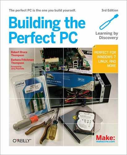
Figure 6-1 shows the core components of the media center system. At the top left of the image, the Antec Fusion Remote media center case sits atop the Antec NSK-2480 media center case. (When we shot this image, we still hadn’t decided which case to use.) On the left are the Crucial Ballistix 4 GB memory kit and Nippon Labs HDMI cable, with a pair of 2 TB Seagate Barracuda XT hard drives to their right. The LiteOn optical drive and the Intel Core i3-530 processor sit atop the Intel DH55TC motherboard, with the Logitech Universal Harmony 300 remote in front of them. The Sharp 42” 1080p HDTV we bought for our media center display wouldn’t fit in the picture.
Choosing a Work Surface
We build systems on the kitchen table because it provides plenty of work room, easy access from the front and rear, and plenty of light, all of which are important. Barbara isn’t happy about having her kitchen table thus occupied, but when Robert explained that the alternative was using her antique dining room table, she grudgingly agreed that the kitchen table was the better choice. Whatever location you choose to build your system, make sure it provides sufficient workspace, easy access, and good lighting. Spousal approval is optional, but highly recommended.
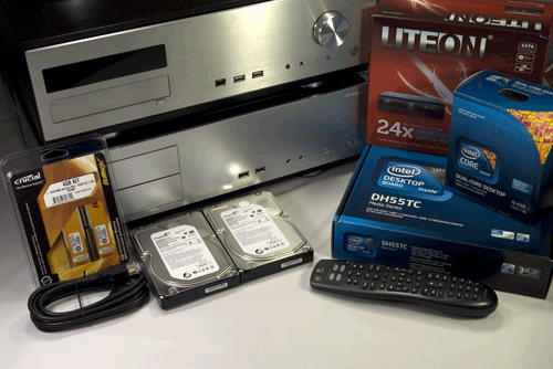
Figure 6-1. Core media center system components, awaiting construction
Before you proceed, verify that you have all of the necessary components. Open each box and confirm that all items on the packing list are present.
Sequencing the Build
You needn’t follow the exact sequence we describe when building your own system. For example, some people prefer to install the drives before installing the motherboard, while others prefer the converse. The best sequence may depend on the case you use and the components you are installing. For example, some case and motherboard combinations make it difficult or impossible to connect the ATX power cable after drives have been installed. Use your best judgment while building the system and you won’t go far wrong.
Preparing the Case
To begin preparing the Antec NSK-2480 case, place it on a flat surface and remove the single thumbscrew at the top rear, as shown in Figure 6-2. Then slide the top panel to the rear and lift it off, as shown in Figure 6-3.
![]() Avoid Fireworks
Avoid Fireworks
Before you do anything else, make sure that the power supply is set to the correct input voltage. Some power supplies, including the EarthWatts 380 unit bundled with the Antec NSK-2480 case, autodetect input voltage and set themselves automatically. Other power supplies require moving a slide switch to indicate the correct input voltage.
If your mains voltage is 115V and the power supply is set for 230V, no damage occurs. The system simply won’t start. However, if your mains voltage is 230V and the power supply expects 115V, you will see a very short and expensive fireworks show the first time you plug in your new system. The motherboard, processor, memory, expansion cards, and drives will all be burnt to a crisp within a fraction of a second.
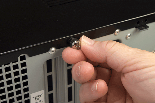
Figure 6-2. Remove the thumbscrew that secures the top panel
Figure 6-3. Slide the top panel to the rear and lift it off
Remove the optical drive bay by sliding it toward the rear of the case, pivoting it upward, and then lifting it free of the chassis, as shown in Figure 6-4.
With the optical drive bay removed, you have access to the bundle of cables from the power supply. Remove the AC power cord and set it aside. Remove the cable wraps that bundle the power supply cables, as shown in Figure 6-5, and straighten out the various cables.
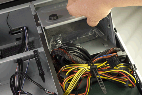
Figure 6-4. Remove the optical drive bay
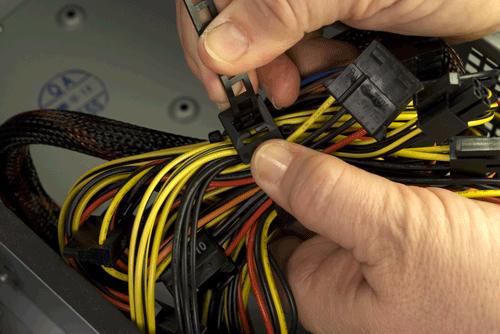
Figure 6-5. Remove the cable tie that secures the bundle of cables from the power supply
Like most cases, the Antec NSK-2480 comes with a generic rear-panel I/O shield. Generic I/O shields don’t fit any motherboard we’ve ever used, so we’re not sure why case makers bother to include them. Removing the generic I/O shield simply adds one more task.
To remove the generic I/O shield, press gently inward on it with a screwdriver handle, as shown in Figure 6-6. Don’t worry about bending the I/O shield, because you’ll discard it anyway. Do take care not to bend the cutout area of the case, which would make it very difficult to install the proper I/O shield. Support the edge of the cutout area with your fingers, and press on the generic I/O shield until it snaps out.
Every motherboard comes with a custom I/O shield that matches the ports on its rear I/O panel. The included I/O shield is nearly always correct, but we have on occasion received a motherboard with an incorrect I/O shield. Before you install the custom I/O shield supplied with the motherboard, compare it against the motherboard I/O panel, as shown in Figure 6-7. If you received the wrong I/O shield, contact the motherboard manufacturer to request a replacement.
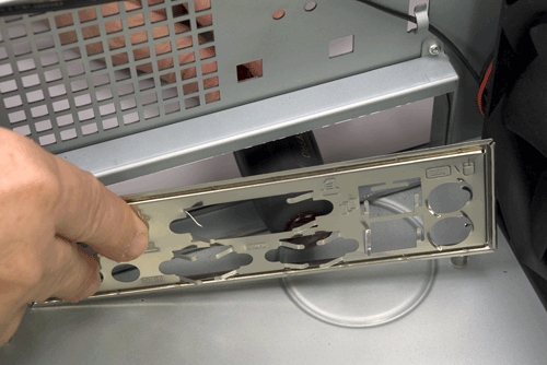
Figure 6-6. Press gently on the generic I/O shield until it snaps out
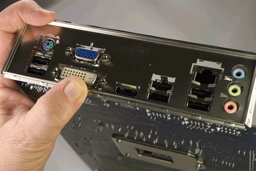
Figure 6-7. Compare the custom I/O shield with the I/O panel of the motherboard
To install the custom I/O shield, first make sure that it’s oriented properly relative to the back-panel motherboard ports. Working from inside the case, align the I/O shield with the cutout. Using a screwdriver handle, start at one corner, as shown in Figure 6-8, and press gently until the I/O shield snaps into place. Run the screwdriver handle around the edges and corners of the I/O shield to ensure that it’s fully seated.
After seating the I/O shield, hold the motherboard aligned in position directly over the case. Compare the positions of the motherboard mounting holes with the standoff mounting positions in the case. The Intel DH55TC has eight mounting holes. The Antec NSK-2480 case has six standoffs preinstalled, all of which correspond to mounting hole positions in the motherboard. Locate and note the two positions that require standoffs to be installed.
Install a brass standoff in each required position, and then use the motherboard again to verify that a standoff is installed at each of the required eight positions. Although you can screw in the standoffs using just your fingers, it’s much easier and faster to use a 5 mm nut driver, as shown in Figure 6-9. Be careful not to overtorque the standoffs as you install them. The standoffs are made of soft brass, and the motherboard tray, although steel, is relatively thin. Applying too much torque can strip the standoff or the screw hole. Finger-tight is good enough, plus maybe an extra quarter turn or so.
![]() Better Safe Than Sorry
Better Safe Than Sorry
Make absolutely sure that every standoff installed corresponds to a motherboard mounting hole. An extra standoff can contact the bottom of the motherboard, causing it to short and possibly damaging or destroying the motherboard and other components.
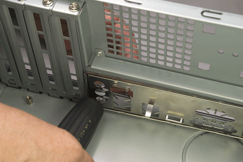
Figure 6-8. Press gently to seat the custom I/O shield
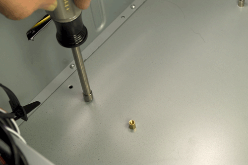
Figure 6-9. Install a standoff in each position that corresponds to a motherboard mounting hole
Preparing the Motherboard
The next step is to prepare the motherboard by installing the processor, CPU cooler, and memory. Although some case and motherboard manuals suggest installing these components after the motherboard has been installed in the case, it’s easier and often safer for the motherboard to mount the processor, cooler, and memory first.
Installing the processor
To begin, locate the processor socket. Ground yourself by touching the chassis, and then release the metal socket lever by pressing it down and away from the socket body. Once the catch releases, lift the lever until it’s fully vertical. Lifting the lever raises the load plate and exposes the socket. Snap out the black plastic socket cover and set it aside. Don’t discard the socket cover. If you ever remove the processor from the socket, you should replace the socket cover to protect the socket until another processor is installed.
Ground yourself to the power supply or chassis frame, and then open the processor package. Snap off the black plastic processor cover and set it aside. Once again, store the processor cover in case you ever need to remove the processor.
The processor and socket are keyed to prevent the processor from being inserted backward into the socket. The gold triangle visible in Figure 6-10 on the left corner of the processor matches a beveled corner on the processor socket. The processor and socket are also keyed with two notches on the edge of the processor that mate with two protruding nubs on the inside edge of the socket. Make sure the processor and socket are aligned properly and then drop the processor straight into the socket, as shown in Figure 6-10. The processor should seat completely without you needing to apply any pressure. If it doesn’t, lift the processor from the socket, recheck the alignment, and try again.
With the socket lever still vertical, lower the load plate, as shown in Figure 6-11.
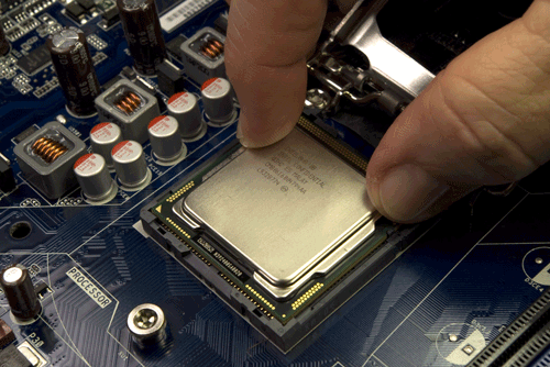
Figure 6-10. Align the processor with the socket and then drop the processor into the socket
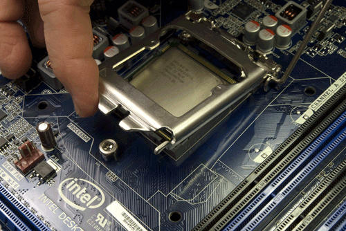
Figure 6-11. Lower the load plate into the closed position
Lower the processor lever to cam the load plate into locked position. Make sure the notch at the front of the load plate latches under the shoulder screw cap, as shown in Figure 6-12.
Press the processor lever flush with the motherboard and snap it into place under the load plate latch, as shown in Figure 6-13.
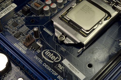
Figure 6-12. Lower the processor lever to cam the load plate into locked position
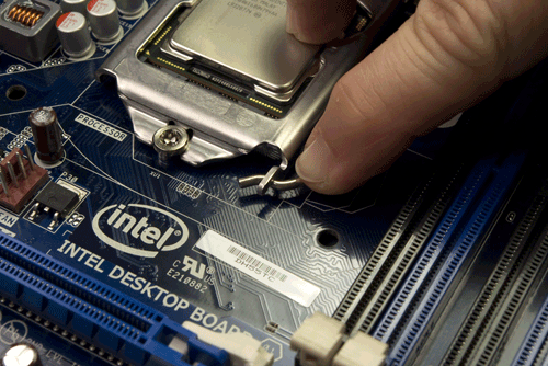
Figure 6-13. Press the processor lever flush with the motherboard and snap it into the load plate latch
Examine the surface of the processor for fingerprints, dust, or other contaminants. If any are present, polish the surface of the processor with a clean paper towel before you proceed to installing the CPU cooler. (If you’re reinstalling the CPU cooler, make sure to remove all of the old thermal compound. You can use a hair dryer to soften it and make it easier to rub off.)
Installing the CPU cooler
Remove the CPU cooler from its packaging and look at the bottom of the cooler. The gray patches on the copper bearing surface of the cooler, visible in Figure 6-14, are thermal compound. This thermal compound melts each time the processor warms up, filling the voids between the surfaces of the processor and the base of the heatsink to ensure good heat transfer. If any of those patches are damaged, carefully rub off any remaining thermal compound, polish the surface of the heatsink base, and apply an approved thermal paste.
The CPU cooler mounts to the motherboard using four posts that protrude through matching holes in the motherboard. Because the posts and holes are in a square pattern, you can install the CPU cooler in any of four orientations. It doesn’t matter which you use, so we generally install the CPU cooler so that the CPU fan power lead has just enough slack to reach the CPU fan power header pins on the motherboard.
You can’t install the CPU cooler with the motherboard on a hard surface because, when seated, the posts protrude slightly on the back side of the motherboard. Placing the motherboard on a soft surface (such as packing foam) allows the posts to penetrate the motherboard and lock into position. If you use foam, make sure to keep the antistatic bag the motherboard was packaged in between the motherboard and the foam. Or, you can do what we usually do, which is to support the motherboard at a slight angle to provide clearance for the posts as we press the posts into place.
To install the CPU cooler, align the tips of its four posts with the four mounting holes in the motherboard. Once all four posts are aligned, press down firmly on one post, as shown in Figure 6-15, until you feel it snap into place.
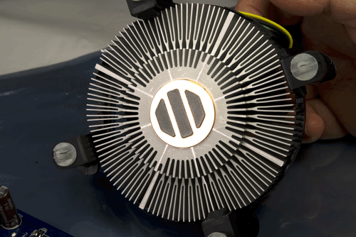
Figure 6-14. Verify that the thermal compound on the copper heatsink base is undamaged
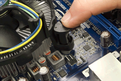
Figure 6-15. Align each CPU cooler post with a mounting hole and press down until it snaps into place
After you seat the posts, use a flat-blade screwdriver to turn the top of each post in the direction of the arrow to lock it into position, as shown in Figure 6-16.
Finally, connect the CPU fan power cable to the CPU fan power header pins on the edge of the motherboard, as shown in Figure 6-17. This connector is keyed. Make sure the slot in the cable connector aligns with the projecting tab on the motherboard header-pin set, and then slide the cable connector onto the pins until it seats.
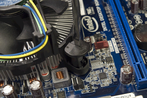
Figure 6-16. Lock each CPU cooler post by turning the head in the direction of the arrow
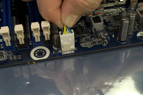
Figure 6-17. Connect the CPU fan power cable to the CPU fan power header pins
Installing memory
The next step is to install the memory modules. The DH55TC motherboard accepts 240-pin DDR3 memory modules. Installing memory modules in pairs enables dual-channel memory operation for faster memory performance.
If you are installing two identical memory modules, install them in the two blue slots. If you are installing two matched pairs of memory modules that differ in capacity, install the higher-capacity pair in the two blue slots and the lower-capacity pair in the black slots. Although it will reduce overall memory performance, you can install three memory modules if two of them are a matched pair. In that case, install the matched pair in the two blue slots, and the third module in either black slot.
In any case, fill the slots nearest the processor first and work forward toward the edge of the board. Ground yourself by touching the power supply or chassis frame before you handle a memory module. To install the first module, position it vertically over the appropriate slot. Align both edges of the module with the slots in the vertical posts on the sides of the slot. DDR3 DIMMs are keyed with an off-center notch on the contact edge of the DIMM. Make sure this notch aligns with the corresponding post in the slot, and then slide the DIMM into position, as shown in Figure 6-18.
After you’ve aligned the module properly, place one thumb on each side of the module and press down firmly until it snaps into place, as shown in Figure 6-19. Repeat this procedure to install any remaining DIMMs.
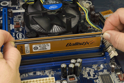
Figure 6-18. Position the memory module with the notch aligned with the socket tab
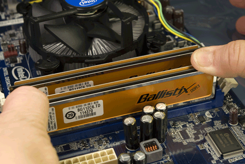
Figure 6-19. Press straight down with both thumbs until the module snaps into place
Installing the Motherboard
Installing the motherboard is the most time-consuming part of the build, because there are so many cables to be connected. Take your time during this phase, because it’s important that all of the cables be connected properly.
Connecting front-panel switch and indicator cables
Ordinarily, we install the motherboard in the case before connecting cables to it, but this combination of motherboard and case has so little clearance that we decided to connect the cables first. If you’re using the Intel DH55TC motherboard and Antec NSK-2480 case, we recommend you do the same. To do so, route the front-panel switch, indicator, and port cables into the motherboard chamber and out the top of the case. Place the protective plastic bag that contained the motherboard on top of the chassis over the motherboard chamber, and balance the motherboard on top of the chassis.
Ron Morse Comments
I like to use a thick towel or something that’s larger than the motherboard just in case it moves around a bit. The little component lead stubs on the back of a motherboard can do a number on the paint finish on the exposed edge of the case.
The only essential front-panel connector is the power switch, which must be connected before you can start the system. You’ll probably also want to connect the reset switch and the hard disk activity LED (shown in Figure 6-20). If you are using a different case, it may have front-panel cables for which there are no corresponding header-pin sets on the motherboard. Conversely, a motherboard may have header-pin sets for which the case has no corresponding cables. For example, the Intel DH55TC motherboard has pins for a power LED, for which the Antec NSK-2480 case does not provide a cable. (The NSK-2480 power LED connects directly to a Molex connector from the power supply. When the system is turned on, the power LED is illuminated.)
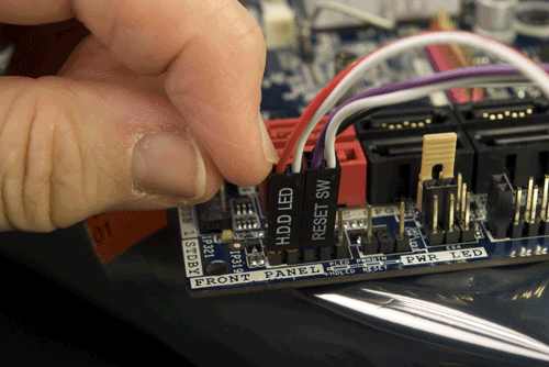
Figure 6-20. Connect the front-panel switch and indicator cables
Before you begin connecting front-panel cables, examine the connectors. Each should be labeled descriptively (POWER SW, RESET SW, HDD LED, and so on). Match those descriptions with the front-panel connector header pins on the motherboard to make sure you connect the correct cables to the appropriate pins. The power and reset switch cables are not polarized and may be connected either way. LED cables may or may not be polarized, but if you connect a polarized LED cable backward the worst that happens is that the LED won’t light up. Most Antec cases use white wires for ground and colored wires for signal. Some cases use black wires for ground, and a few use green.
When you’re connecting front-panel cables, try to get it right the first time, but don’t worry too much about getting it wrong. Other than the power switch cable, which must be connected properly for the system to start, none of the other front-panel switch and indicator cables are essential, and connecting them incorrectly won’t damage the system.
![]() Bright Lights
Bright Lights
The NSK-2480 power LED and HDD LED are quite bright. They’re not intrusive in a normally lit room or if you’re not looking directly at the system, but in a typical home theater setup the lights are often dimmed and the media center system is usually quite close to the television. Under those conditions, you may find the power and HDD LEDs distracting. For that reason, some builders don’t bother to connect them. The only downside to doing that is that if you later decide you want those indicators working, you may have some difficulty getting the cables connected. We suggest that you connect the power and HDD LEDs initially. If you decide they’re too bright, you can disconnect them easily.
Connecting front-panel audio
The NSK-2480 front-panel audio cable terminates in two connectors, one labeled HD AUDIO and the other FP’97. The motherboard HD audio front-panel audio connector is located near the PCI expansion slot and is keyed with a missing pin. The audio cable HD audio connector has a corresponding blocked hole, to prevent the connector from being installed backward. Align the HD audio cable connector over the HD audio header-pin set on the motherboard, and press the cable connector straight down until it seats completely, as shown in Figure 6-21.
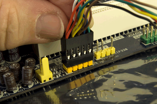
Figure 6-21. Connect the front-panel audio cable to the motherboard HD audio connector
Connecting front-panel USB ports
The Antec NSK-2480 case provides two front-panel USB ports with cables that terminate in one Intel-standard dual-USB connector. Locate that cable, which is labeled USB, and connect it to one of the three dual-USB motherboard connectors located near the left front edge of the motherboard near the SATA ports, as shown in Figure 6-22. The motherboard connector is keyed with a missing pin that corresponds to a blocked hole on the cable connector, so it’s difficult to connect the cable incorrectly. (However, it is possible to offset the cable connector against the motherboard connector and still seat the connector.) Note that we chose to use the FP USB 2 header-pin set, which can instead be used to connect an internal Intel SSD. We have no plans to install such a drive, and this header-pin set is perfectly usable for a standard USB front-panel connection.
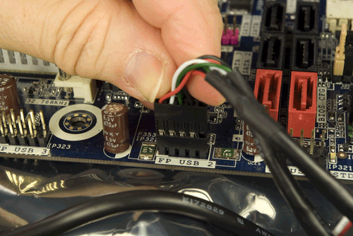
Figure 6-22. Connect the front-panel USB cable to a motherboard dual-USB connector
Seating and securing the motherboard
To begin, lower the motherboard into the case, as shown in Figure 6-23, with the front edge of the motherboard slightly raised. Carefully align the back-panel I/O connectors with the corresponding holes in the I/O shield, and slide the motherboard toward the rear of the case as you lower the motherboard to horizontal. This process is hard to describe, but easy to do. The goal is to get the back-panel ports on the motherboard low enough that they come into contact with the I/O shield grounding tabs, without those tabs intruding into the ports themselves. (The Ethernet grounding tab is usually the problem; we’ve been known to bend that tab slightly upward to facilitate installing the motherboard and then bend it back down into contact afterward.)
Maintain slight rearward pressure on the motherboard to keep it in contact with the I/O shield. Examine the rear I/O panel to make sure that none of the I/O shield grounding tabs intrude into a port connector. More than once, we’ve mounted a motherboard, inserted all the screws, and connected all the cables before we noticed that there was a metal tab sticking into one of our USB or LAN ports. Before you secure the motherboard in place, verify that the back-panel I/O connectors are mated cleanly with the I/O shield, as shown in Figure 6-24. A bright flashlight can be very helpful here.
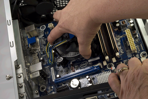
Figure 6-23. Slide the motherboard into position
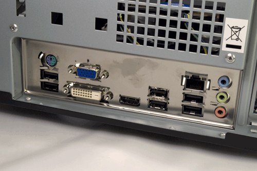
Figure 6-24. Make sure the back-panel connectors mate cleanly with the I/O shield
Once the motherboard is positioned properly and you have verified that the back-panel I/O port connectors are mated cleanly with the I/O shield, insert a screw through each motherboard mounting hole into the corresponding standoff, as shown in Figure 6-25. For the first two or three screws, you may have to apply pressure with one hand to keep the holes and standoffs aligned while driving the screw with the other.
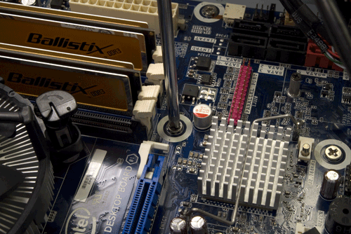
Figure 6-25. Securing the motherboard
At times it’s difficult to get all the holes and standoffs aligned. If that occurs, insert two screws into easily accessible positions, but don’t tighten the screws completely. You should then be able to force the motherboard into complete alignment, with all holes matching the standoffs. At that point, insert one or two more screws into standoffs and tighten them completely. Finish mounting the motherboard by inserting screws into all the standoffs and tightening them. Don’t put excessive force on the screws, or you may crack the motherboard. Finger-tight is plenty, plus at most a quarter turn.
Screwed
Although the problem is more common with cheap motherboards and cases, even if you’re using high-quality components it can be difficult, if not impossible, to get all of the mounting holes aligned with the standoffs. There simply isn’t much slack to work with. With high-quality components, everything usually lines up perfectly (although it may take some pressure). But if you find yourself unable to insert all of the motherboard mounting screws, don’t despair. We like to get all the screws installed, both for physical support and to make sure all of the grounding points on the motherboard are grounded, but getting most of them installed—say six or seven of the eight—is normally good enough.
If you are unable to install all of the screws, take the time to remove the brass standoffs where no screw will be installed. A misaligned standoff may short something out. In situations where we couldn’t use all of the brass standoffs because of alignment issues, we have been known to trim double chopsticks to length and install them as substitute standoffs. They’re the right thickness to support the motherboard and are made of non-conducting wood.
It’s particularly important to provide some support for the motherboard near the expansion slots, where significant pressure may be applied when installing cards. If the motherboard is unsupported, pressing down on it may crack it.
Connecting SATA data cables
The next step is to connect the SATA data cables for the hard drives and the optical drive. The Intel DH55TC motherboard provides a cluster of six SATA connectors near the left front corner of the motherboard. Four of these, color-coded black, are standard SATA data connectors. Two, color-coded red, are eSATA connectors, which may be used to connect standard SATA devices as well as eSATA devices. Intel properly labels the four standard connectors SATA 0 through SATA 3. (Some motherboards begin numbering at SATA 1.) We’ll connect our two hard drives to SATA ports 0 and 1, and our optical drive to SATA port 2.
Locate three SATA data cables, which may be supplied with the motherboard, the drives, or both. Connect those SATA data cables to SATA ports 0, 1, and 2, as shown in Figure 6-26. Align the cable connector with the motherboard connector, making sure that the L-shaped keys on both connectors are oriented properly, and then press the cable connector straight down until it seats in the motherboard connector. (As a close examination of Figure 6-26 shows, we actually used three different SATA cables; they just happened to be the first three we pulled from our supplies closet.)
![]() Playing Both Ends Against the Middle
Playing Both Ends Against the Middle
Both ends of a SATA cable are identical in terms of pin assignments and keying, so it usually doesn’t matter which end you connect to the motherboard and which to the drive. Many SATA cables have simple plastic connectors on both ends, but some, including those supplied with some Intel motherboards, have metal latching connectors on one or both ends that are designed to lock the cable to the connector.
If you subsequently remove such a cable, make sure to press the latch to disconnect it before you pull the cable, or you may damage the motherboard connector and/or the cable. Back in the days when latching SATA connectors were still very uncommon, we once pulled a SATA cable from a motherboard without watching what we were doing. We heard a loud cracking noise. Fortunately, it was the cable we damaged rather than the motherboard, but it might easily have been otherwise.
The two hard drive SATA data cables can remain in the motherboard chamber for now, but we need to route the optical drive SATA data cable through the bulkhead and into the chamber that contains the power supply and optical drive. To do so, loosen the screw that secures the sliding access panel in the bulkhead, as shown in Figure 6-27, and slide the panel fully open.
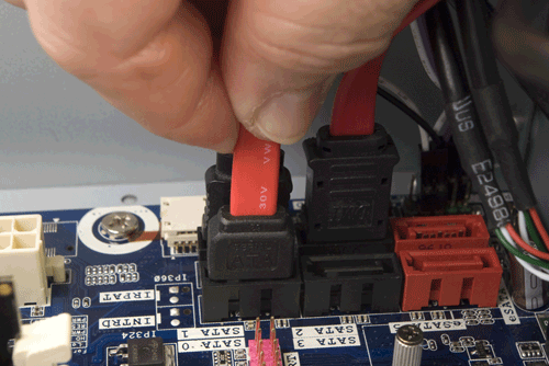
Figure 6-26. Connect the SATA data cables to the motherboard ports
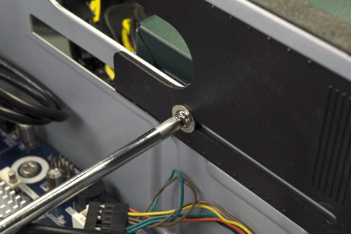
Figure 6-27. Loosen the screw that secures the access panel
Pass the free end of the optical drive SATA data cable through the access door and into the chamber that contains the optical drive bay, as shown in Figure 6-28.
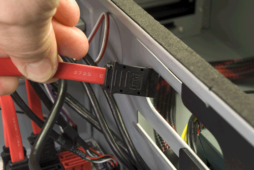
Figure 6-28. Pass the SATA data cable for the optical drive into the power supply chamber
Routing and connecting power to the motherboard
The next step is to route the main ATX power cable and the ATX12V (CPU) power cable from the power supply chamber to the motherboard chamber and connect those cables. To begin, pass the 24-pin main ATX power cable from the power supply chamber into the motherboard chamber, as shown in Figure 6-29.
Align the 24-pin main ATX power cable connector with the motherboard socket, as shown in Figure 6-30, and press down firmly until it snaps into place. Examine the connection visually to verify that the connectors are fully mated and that the latch has engaged. A partially seated main ATX power connector can cause subtle problems that are very difficult to troubleshoot.
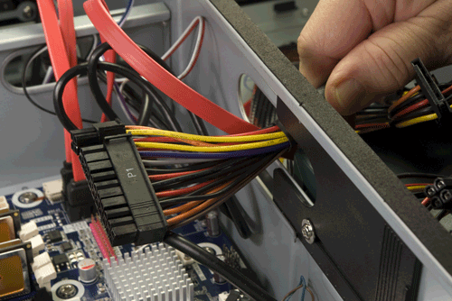
Figure 6-29. Route the main ATX power cable from the power supply chamber into the main chamber
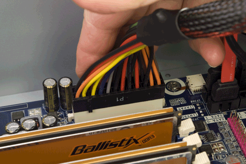
Figure 6-30. Connect the main ATX power cable
The next step is to route and connect the ATX12V power cable, as shown in Figures 6-31 and 6-32. The ATX12V motherboard connector is located between the CPU socket and the rear I/O panel. Orient the ATX12V cable properly, and press down firmly until it snaps into place. Examine the connection to make sure that the latch is engaged.
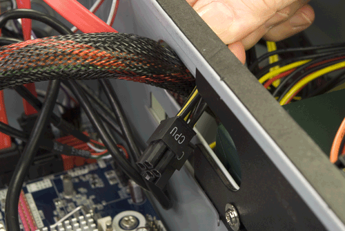
Figure 6-31. Route the ATX12V power cable from the power supply chamber into the main chamber
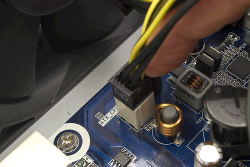
Figure 6-32. Connect the ATX12V power cable
Installing the Optical Drive
The next step is to install the optical drive. The Antec NSK-2480 case provides two external 5.25” drive bays, either or both of which can be used for optical drives or other 5.25” devices, such as the Antec Easy SATA hard drive docking station. To begin installing the optical drive, press the inside of the plastic bezel until it snaps out, as shown in Figure 6-33.
Locate the optical drive cage that you set aside earlier. Slide the optical drive into the cage and use four or more of the provided screws to secure it, as shown in Figure 6-34. Make sure to orient and position the optical drive as shown. It needs to protrude from the front of the drive cage if you want the optical drive bezel to be flush with the case bezel.
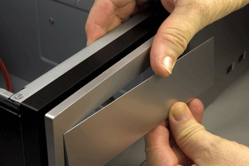
Figure 6-33. Snap out the plastic bezel from a 5.25” external drive bay
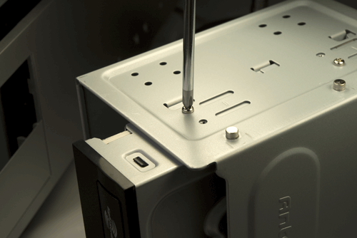
Figure 6-34. Secure the optical drive to the bay with four screws
Slide the optical drive cage into the case with the front tilted downward, as shown in Figure 6-35.
Lower the rear of the optical drive cage, making sure that the projecting nubs on the cage frame fit into the cutouts on the chassis, and then slide the optical drive cage into the locked position, as shown in Figure 6-36.
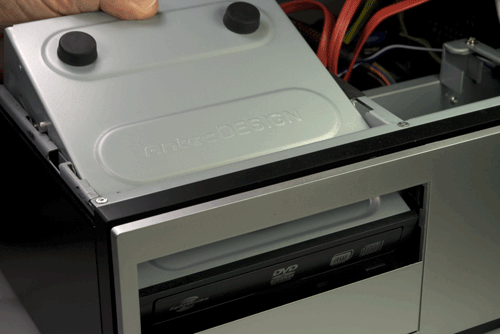
Figure 6-35. Slide the optical drive cage into the case
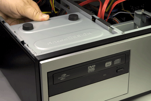
Figure 6-36. Slide the optical drive cage into the chassis
Locate an available SATA power cable from the power supply and connect it to the optical drive power connector, as shown in Figure 6-37. (We used the SATA power cable with the P5 connector.) Make sure the L-shaped keys on the cable connector and drive connector are aligned properly, and then press the cable connector onto the drive connector until it seats completely.
Locate the SATA data cable that you previously fed through from the motherboard chamber to the power supply chamber, and connect that SATA data cable to the optical drive, as shown in Figure 6-38. Make sure the keying on the drive and cable connectors is aligned properly, and then press the connector into place until it’s fully seated.
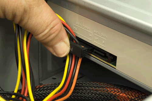
Figure 6-37. Connect a SATA power cable to the optical drive
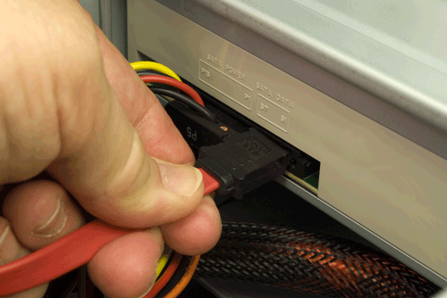
Figure 6-38. Connect the SATA data cable to the optical drive
Routing Drive Power Cables to the Motherboard Chamber
The next step is to route power cables for the hard drives, fan, and power LED from the power supply chamber into the motherboard chamber. We’ll need Molex power connectors for the power LED and both case fans, and two SATA power connectors for the hard drives. Depending on your configuration, it can be important which cables you choose to route. Obviously, you need the right number and type of power connectors for the devices you need to connect. Less obviously, depending on your power supply, some cables may be longer or shorter than others, or may have the wrong type of connector in the right place, or vice versa. We routed the P2 cable (shown in Figure 6-39) and the P10 cable (shown in Figure 6-40) into the motherboard chamber. That combination works for the configuration we used, but again, check your own configuration to be sure.
Draw sufficient length of each cable into the motherboard chamber to reach the devices you need to connect. Don’t forget to allow some slack for cable dressing. Once you’ve done that, you can slide the bulkhead access door closed, as shown in Figure 6-41, and tighten the screw that secures it.
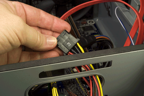
Figure 6-39. Routing the P2 cable into the motherboard chamber
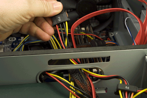
Figure 6-40. Routing the P10 cable into the motherboard chamber
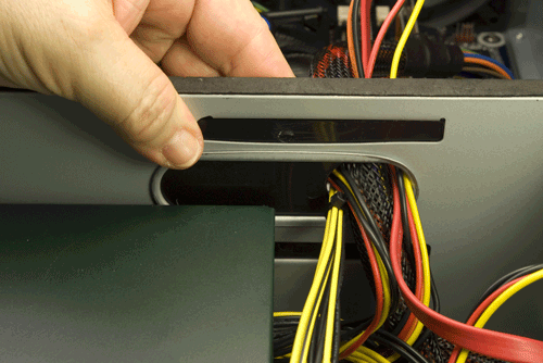
Figure 6-41. Slide the bulkhead access door closed
Installing the Hard Drive(s)
The next step is to install the hard drive(s), a task that’s considerably more involved with the NSK-2480 than it is with most cases. The NSK-2480 mounts one or two hard drives vertically in a separate chamber at the front of the case. In most cases, you can install hard drives and connect the power and data cables without much regard for sequence. In the NSK-2480, the sequence is important because access to the drive connectors is restricted after you’ve inserted them in the cage. To begin, remove the four screws that secure the top plate of the hard drive chamber, as shown in Figure 6-42, and then remove the top plate, as shown in Figure 6-43, and set it aside.
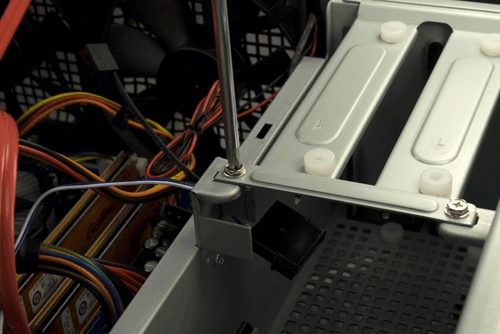
Figure 6-42. Remove the four screws that secure the top plate of the hard drive chamber
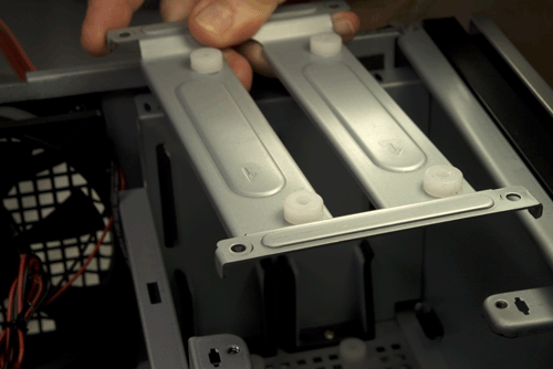
Figure 6-43. Remove the top plate from the hard drive chamber
Connect an available SATA power cable to the first hard drive, as shown in Figure 6-44. We used the P9 connector.
P9 or P6?
We mentioned the connector by number not because of function or power provisioning, but simply to indicate which connector we found most convenient to use because of cable length, connector positioning, and so on.
Connect a SATA data cable to the first hard drive, as shown in Figure 6-45.
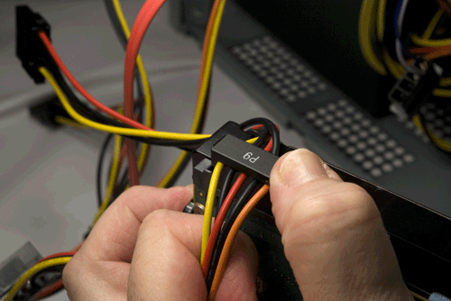
Figure 6-44. Connect a SATA power cable to the first hard drive
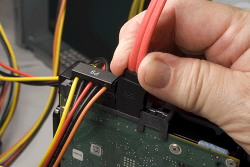
Figure 6-45. Connect a SATA data cable to the first hard drive
Slide the first hard drive into the hard drive chamber, oriented as shown in Figure 6-46.
Hard drives can be secured with two screws driven through the top plate and (optionally, according to Antec) with two more screws driven through the bottom of the case. Rather than having our hard drives hanging like bats, suspended from the top plate and free-floating on the bottom, we prefer to secure our drives with four screws as usual. To do that, turn the case on its side, while supporting the hard drive to make sure it doesn’t fall out. Use one hand to wiggle the hard drive back and forth until the grommeted screw holes in the bottom of the case align with the drive screw holes. Drive in two screws, as shown in Figure 6-47, to secure the drive to the bottom of the case.
To install the second hard drive, connect a SATA data cable and a SATA power cable, as shown in Figures 6-48 and 6-49.
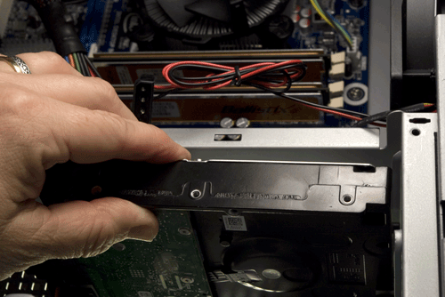
Figure 6-46. Slide the first hard drive into the hard drive chamber
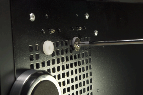
Figure 6-47. Secure the first hard drive with two screws through the bottom of the case
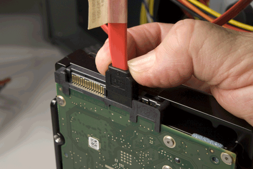
Figure 6-48. Connect a SATA data cable to the second hard drive
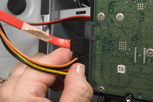
Figure 6-49. Connect a SATA power cable to the second hard drive
Slide the second hard drive into the hard drive bay, wiggle it back and forth until the screw holes in the drive align with those in the chassis, and secure the drive to the chassis by driving in two hard drive mounting screws, as shown in Figure 6-50.
Figure 6-51 shows both hard drives properly mounted.
The next step is to replace the top plate on the hard drive bay and secure each hard drive by driving two hard drive mounting screws through the plate and into the drive, as shown in Figure 6-52.
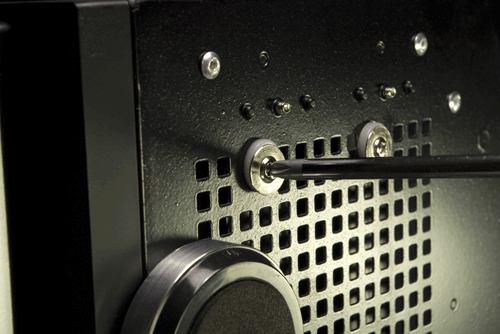
Figure 6-50. Secure the second hard drive to the chassis by driving two hard drive mounting screws through the bottom of the case and into the drive
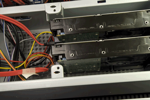
Figure 6-51. Both hard drives properly mounted
The final step in installing the hard drives is to reinstall the four screws that secure the top plate to the hard drive bay, as shown in Figure 6-53.
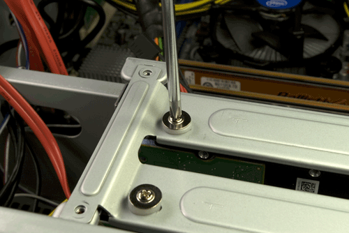
Figure 6-52. Secure both hard drives to the top plate of the hard drive bay by driving two hard drive mounting screws into each drive
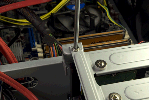
Figure 6-53. Secure the top plate to the hard drive bay by driving in four screws
Installing the Expansion Cards
If you have a video adapter or expansion cards to install, now is the time to do it. We had only a half-height PCI wireless networking card to install, and we actually installed it earlier in the build. Then, as we were writing this section, we realized that we should shift this step to very late in the build. The potential problem is that a full-length, full-height expansion card may block the sliding access plate in the bulkhead, making it difficult to route cables from the power supply chamber to the motherboard chamber.
To begin installing your expansion card(s), determine which card(s) will occupy which slot(s), and therefore which expansion slot covers you need to remove. You can do that by holding the card in position against the appropriate motherboard slot and determining which expansion slot cover that card’s expansion bracket covers. Once you’ve determined that, remove the screw that secures the expansion slot cover, as shown in Figure 6-54.
With the screw removed, tilt the expansion slot cover slightly toward the front of the case, as shown in Figure 6-55, and pull straight up to remove it.
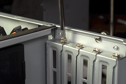
Figure 6-54. Remove the screw that secures the expansion slot cover
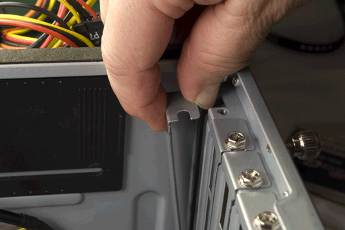
Figure 6-55. Tilt the expansion slot cover toward the inside of the case and pull it free
![]() Check the Latch, Both Ways
Check the Latch, Both Ways
A plastic retention mechanism is used to secure a PCI Express video adapter in the slot. When you install a video adapter, make sure the retention mechanism latches. When you remove a video adapter, make sure to unlatch the retention mechanism before you attempt to remove the card from the slot.
Align the contact edge of the expansion card with the slot and press down firmly to seat the card, as shown in Figure 6-56. Verify visually that the card is fully seated. Video adapters are particularly problematic. The video adapter may appear to seat. You may even feel it snap into place. That doesn’t guarantee that it’s completely seated. Always examine the slot carefully to make sure that the card is fully seated and level in the slot, with the top edge of the card contacts flush with the top edge of the slot. After you seat each expansion card, reinsert the screw to secure the bracket to the chassis. After you tighten the screw in the retaining bracket, double-check to make sure the card is completely seated in its slot. (Sometimes, driving the screw into the bracket can twist the card up and out of the slot slightly; in that situation, you’re better off omitting the screw entirely.)
If the expansion card has any sort of external dongle, antenna, or other connector, hook it up now. For example, Figure 6-57 shows Barbara attaching the antenna to the WiFi card.
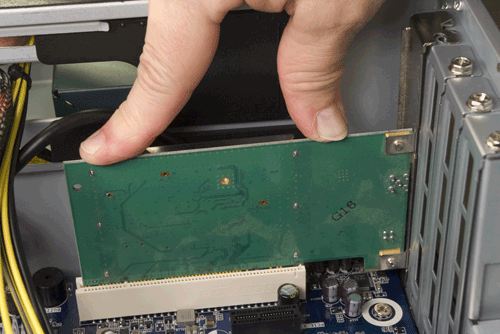
Figure 6-56. Align the expansion card with the slot and press down firmly to seat it
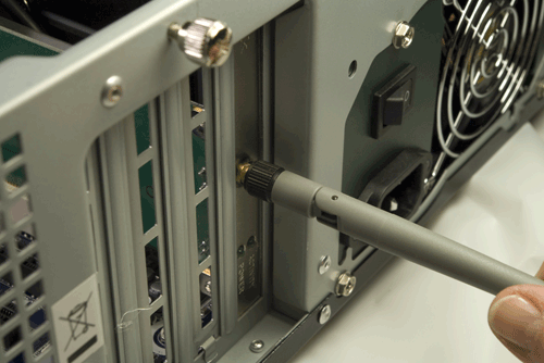
Figure 6-57. Connect the WiFi antenna to the back of the card
Finishing Up
We’re in the home stretch now. All that remains is to connect power to the case fans and the power LED (if you choose to do that), and a few minor cleanup tasks. Figures 6-58, 6-59, and 6-60 show Barbara connecting power for the power LED, using connector P10, and to the case fans using the P2/P3 connectors.
Figure 6-61 shows our media center system at this point in the build. Obviously, we can’t leave that rats’ nest of cables flopping around in there where they might foul a fan, so the next task is to dress the cables.
Nobody’s Perfect
One of our tech reviewers asked if the SATA data cables should have been routed through the cutout between the motherboard chamber and the hard drive chamber, and whether there was sufficient clearance for the cover with the SATA cables run over the top edge of the bulkhead (as it isn’t clear in the image). The answer to both of those questions is yes. We should have routed the SATA cables through the cutout, but we didn’t notice that until after we’d finished building the system. And there is sufficient clearance between the top edge of the bulkhead and the case cover, so we elected to leave the cables as they were and simply tie them off to the chassis frame.
As Figure 6-62 shows, even at full extension the ATX12V cable wasn’t long enough to route along an edge of the motherboard, so we did the best we could. We tried it both ways, running it along the back of the motherboard as well as the front. We got the fan power cables secured away from the blades and used the cable wraps to tie the cable bundles to the chassis. While we were at it, we rerouted the SATA data cables to run them through the chassis cutout visible underneath them in the preceding image.
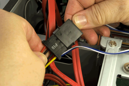
Figure 6-58. Connect power to the power LED
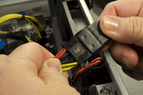
Figure 6-59. Connect power to the first case fan
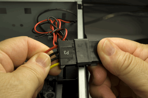
Figure 6-60. Connect power to the second case fan
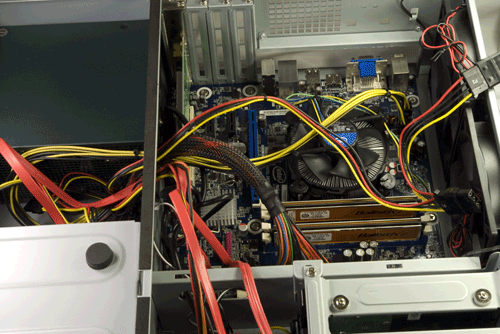
Figure 6-61. Our media center system, before cleanup
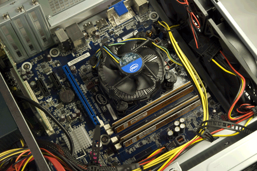
Figure 6-62. The final system, with cables dressed
The CPU fan cable was obnoxious. It was too short to route and dress the way we wanted to, and too long to leave flopping loose. We finally looped it over one of the CPU cooler posts and declared the job done. (Until we powered up the system for the smoke test and quickly realized that the CPU fan cable had fouled the CPU fan.)
Once you have the cables dressed, take a few minutes to double-check everything one last time before you apply power to the system. Use the following checklist:
No loose tools or screws (shake the case gently)
CPU cooler properly mounted; CPU fan connected
Memory modules fully seated and latched
Front-panel switch and indicator cables connected properly
Front-panel I/O cables connected properly
Hard drive data cables connected to drive and motherboard
Hard drive power cables connected
Optical drive data cable connected to drive and motherboard
Optical drive power cable connected
All drives secured to drive bay or chassis, as applicable
Expansion cards fully seated and secured to chassis
Main ATX power cable and ATX12V power cable connected
All cables dressed and tucked
Once you’re certain that all is as it should be, it’s time for the smoke test. Leave the cover off for now. Connect the power cable to the wall receptacle and then to the system unit. Flip the rear power switch from 0 to 1. Press the main power button on the front of the case, and the system should start up. Check to make sure that the power supply fan and CPU fan are spinning. You should also hear the hard drives spin up. At that point, everything should be working properly.
Only the Good Die Young
When you turn on the rear power switch, the system will come to life momentarily and then die. That’s perfectly normal behavior. When the power supply receives power, it begins to start up. It quickly notices that the motherboard hasn’t told it to start, though, so it shuts down again. All you need to do is press the front-panel power switch and the system will start normally.
After the system passes the smoke test, turn it off and connect the keyboard, mouse, display, and any other external peripherals. When the BIOS Setup screen appears, run BIOS Setup and verify that all hardware is recognized and that the date and time are set correctly. Verify that the optical drive is first in the boot sequence screen. If you’ve installed a removable or eSATA hard drive, make sure to configure the IDE/ATA options to enable AHCI. Once BIOS Setup is the way you want it, save your changes and exit. Put your operating system disc in the optical drive and turn the system off. Restart it and install the operating system.
Ron Morse Comments
Robert makes a good case for preferring the eSATA interface over the slower USB connection for removable, “hot-pluggable” storage devices, but there’s a potential gotcha: it only works if both the SATA disk controller on the motherboard and the operating system support it.
You won’t have a problem if you follow Robert’s recommendations for the hardware and use Linux, Windows Vista, or Windows 7 as your operating system, but Windows XP doesn’t support AHCI—at least, not without a complicated and error-prone modification to the system software. If for some reason you find yourself using Windows XP as the operating system on your media center PC, leave the BIOS setting for the SATA controller in default IDE mode and make do with the USB interface for external storage
Installing Software
Now that we’ve built the system, it’s time to install the software we need. For each of the first two editions of this book, we spent a couple of weeks installing and testing scads of media center applications, everything from Windows Media Center Edition to third-party Windows PVR apps to half a dozen Linux media center apps. We played around with numerous handheld remotes and IR receivers and spent time tweaking various software plug-ins to do things like convert recorded TV programs to DVD format or send commands to a cable box to turn it on and change channels.
We started to do the same thing this time, looking at Windows 7, Mythbuntu, LinuxMCE, and many other media center apps. Then it finally hit us. If we won’t use our media center system to record TV programs, we don’t need any of this specialized software. With an HDTV, we don’t need a low-resolution 10-foot interface and a handheld remote to control the system. We can do everything we need to do with Windows 7 or a standard Linux distribution with a standard wireless keyboard and mouse, and you probably can, too.
Ron Morse Comments
I think Windows 7 Media Center is by far the best way to go for someone who needs broadcast/cable/satellite TV and PVR. Microsoft has finally gotten all of the integration sorted and debugged. I don’t think Media Center has blown up on me even once, even back during the public beta stage.
Windows certainly has some very nice features, and for many people it will be the perfect media center operating system. But Linux also has some very nice features, and since we run Linux on all of our other systems, we decided to make our media center system Linux-based as well. Even if you’re a Windows or OS X household, you may well find that Linux is the best choice for your media center system. If nothing else, Linux and all of the applications we feature in this section cost nothing, which can save you several hundred dollars on your new media center system.
Of course, you may decide to run Windows 7 on your media center system, either because you’re just more comfortable with it or because you intend to use the system for gaming, or both. (Linux positively suX0rz for gaming. If we decide to run games, we’ll buy an xBox, PS3, or Wii console.)
Brian Bilbrey Comments
But that may be changing once again, since Valve is bringing its Steam platform and a bunch of games to Linux, theoretically in autumn 2010. And of course, there’s Cedega, which is a gaming-oriented commercial wrapper around WINE. I’ve used that for several Windows games over the years.
Operating System
Ubuntu Linux (http://www.ubuntu.com)
We chose Ubuntu Linux for our media center system, mainly because it’s what we run on all of our other PCs. Ubuntu is the most popular desktop Linux distribution, and for good reason. It’s newbie-friendly, well maintained, and has a huge selection of freely downloadable software available in its repositories. Nearly any Linux application you might want to use is likely to be available in a version for Ubuntu. If you’re already comfortable with another Linux distribution, use it. But if you’re new to Linux, Ubuntu is an excellent way to get started.
To install Ubuntu, visit the website and download the ISO file. Burn that file to a CD in ISO mode. (That is, burn the downloaded ISO file as a disc image rather than as an individual file.) If you’re downloading the Linux ISO to a Windows system and don’t have disc-burning software that can burn ISO image files, download and install ImgBurn (http://www.imgburn.com).
Make sure you’ve set up the BIOS to boot from the optical drive, insert the disc in the drive, start the system, and follow the prompts to install Ubuntu. (If during installation you have no clue about which options to select, just accept the defaults.) As soon as the installation is complete and the system reboots, click the System menu, choose Update Manager, and allow Ubuntu to download and install all updates.
The standard Ubuntu distribution includes by default most of the general-purpose applications you might need—things like OpenOffice.org for word processing and spreadsheets, Firefox for web browsing, and so on. But there’s tons more stuff available, and all at no cost. Anything we might need for our media center system is available for Linux. Those Linux applications are usually at least as capable as similar apps available for Windows, and often more so.
Windows users are invariably surprised when they see how easy it is to install Linux apps. In Ubuntu, you can simply click Add/Remove from the Applications menu, select the application or applications you want to install, and click Apply Changes. Linux automatically downloads and installs the new application(s). If a new application requires supporting files that aren’t already installed on your system, those additional files are automatically downloaded and installed as well. Figure 6-63 shows the Ubuntu Add/Remove dialog just after we installed LAME (the consensus best MP3 encoder), which is included in the Ubuntu Restricted Extras package.
Mythbuntu for TV Recording
If you did install a TV tuner card or cards in your media center system, you can make things a lot easier by installing Mythbuntu (http://mythbuntu.org) rather than the standard Ubuntu distribution. Mythbuntu is a modified version of Ubuntu that has MythTV preinstalled and preconfigured. By default, Mythbuntu uses the minimalist XFCE user interface and does not install the general-purpose applications that are bundled with the Ubuntu distribution, but Mythbuntu is actually Ubuntu under the hood. You can have the capabilities of both Ubuntu and Mythbuntu simply by installing Mythbuntu and then using the Control Centre to install the ubuntu-desktop package and any other packages you need.
If you do decide to install Mythbuntu for PVR functions, we strongly recommend you check their supported hardware list and hew rigorously to it. During a back-channel conversation between Robert and our tech reviewers, Ron Morse—who’s forgotten more about Linux than Robert ever learned—commented that, despite playing with it extensively, he’d never been able to get Mythbuntu to work. Robert replied that he’d installed Mythbuntu (and earlier versions of MythPC) on several systems, as far back as 2004, and had never had a problem getting it to work.
The reason for that difference became clear as the conversation continued: Robert had used only the exact components that appeared on the supported hardware list. Ron had tried to use some components that were very similar to supported components (e.g., a different model of tuner card, but one based on the same chipset as a supported tuner card). Close doesn’t cut it with Mythbuntu. If you’re going to try it, do it right. Make sure every component you use is explicitly listed as supported.
Or, as Ron suggests, install a version of Windows 7 that includes Media Center and have done with it.
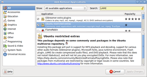
Figure 6-63. The Ubuntu Add/Remove Applications dialog
Audio CD Ripping and Encoding
K3b + LAME (Ubuntu repositories)
Ripping a CD is the process of extracting the original music tracks from an original audio CD as WAV files. Encoding is the process of converting those WAV files to some other audio format, such as MP3. There are dozens of audio CD rippers available for Linux, but the one we find ourselves coming back to every time we try something different is K3b (KDE Burn, Baby, Burn), shown in Figure 6-64, which is also the best disc burning application available for Linux. To install K3b, click the Ubuntu Applications menu and choose Add/Remove. When the Add/Remove Applications dialog appears, type “K3b” in the search box. Mark the K3b checkbox, and click the Apply Changes button.
Like the gold-standard Windows application Exact Audio Copy, K3b performs extremely accurate rips. It’s also very convenient to use, particularly if you have a huge stack of audio CDs to rip. As you insert each audio CD, K3b automatically looks up the CDDB track information, rips the audio data to WAV files (which can be deleted automatically as processing for each CD is complete), and encodes those WAV files as MP3 files or in another format you specify. All you have to do is insert a new audio CD each time K3b finishes processing the last one and ejects it.
Some years ago, we ripped our entire collection of audio CDs to uncompressed WAV files, because we wanted the best possible audio quality. Unfortunately, a typical audio CD contains about 600 MB of WAV files, so our collection of several hundred CDs occupied about 500 GB of disk space. As it turned out, that was overkill.
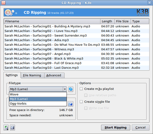
Figure 6-64. Ripping and encoding an audio CD with K3b and LAME
We did some listening comparison tests, putting the original WAV files up against MP3 files compressed with the LAME encoder set to use the “insane” preset, which encodes MP3 audio at 320 kb/s VBR (variable bit rate). Listening with a high-quality receiver and speakers, we couldn’t tell any difference at all between the uncompressed files and the MP3 files. So we re-encoded all of those tracks to MP3 files, reducing our storage requirements from 500 GB to about 125 GB and at the same time quadrupling the number of tracks that fit on Barbara’s MP3 players.
If you decide to rip and encode your audio CD collection, we strongly recommend that you encode your tracks as MP3 files for maximum compatibility with portable players and so on. And, if you decide to encode to MP3, don’t even think about using any encoder other than LAME. Nothing else comes close to LAME in audio quality. Use the LAME “insane” preset for the best possible audio quality.
Unfortunately, installing K3b does not install the LAME encoder by default. To get LAME, click on the Ubuntu Applications menu and run Add/Remove Applications to install the Ubuntu Restricted Extras package, as described previously. Once LAME is installed, put an audio CD in the drive, run K3b, and choose Rip Audio CD from the Tools menu. When the CD Ripping dialog appears, click the gear tool next to the Filetype drop-down list, and configure LAME to your preferences. Figure 6-65 shows the LAME command-line options we use.
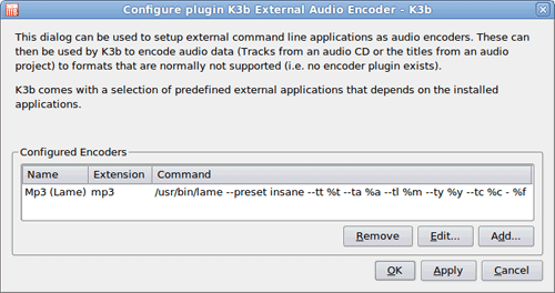
Figure 6-65. The External Audio Encoder dialog, where LAME is configured
Music Management
Rhythmbox Music Player (default)
Amarok (Ubuntu repositories)
If your CD collection is anything near the size of ours, you’ll end up with an MP3 directory that contains hundreds of subdirectories, which in turn contain thousands to tens of thousands of MP3 files. Just double-clicking any of those MP3 files will start it playing, but that’s obviously not an ideal way to manage your music collection. Fortunately, there are at least two good Linux applications available to manage your music files.
By default, Ubuntu installs the Rhythmbox music player, shown in Figure 6-66. Rhythmbox is essentially a partial clone of the iTunes application, except that it points to free music stores rather than the commercial Apple iTunes service. Rhythmbox provides all of the basic music management/player features, along with some nice extras such as smart playlists and the ability to burn a playlist to CD. Rhythmbox is a bit light on features for our tastes, but it’s extremely popular and may be all you need.
To start using Rhythmbox, open the Ubuntu Applications menu, choose the Sound & Video submenu, and click Rhythmbox Music Player. Open the Rhythmbox Edit menu, choose Preferences, point it to your MP3 directory, and set up Rhythmbox the way you want it. It will scan and index your audio collection automatically, a process that took less than half an hour when run against our 125 GB music directory. Once the indexing completes, you’re ready to roll.
The other standout choice among Linux music managers is Amarok, shown in Figure 6-67. Amarok supports every music management/player feature we can imagine, and then some. It’s not included in the standard Ubuntu distribution, so if you want to use it you’ll have to add it manually. To do so, click the Ubuntu Applications menu and choose Add/Remove. When the Add/Remove Applications dialog appears, type “Amarok” in the search box. Mark the Amarok checkbox, and click the Apply Changes button.
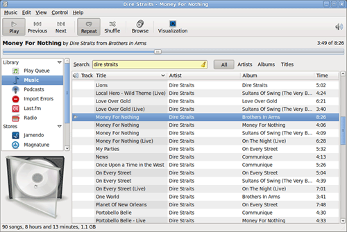
Figure 6-66. The Rhythmbox music player main screen
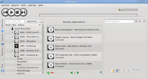
Figure 6-67. The Amarok music player main screen
Once Amarok is installed, open the Settings menu and choose Configure Amarok to display the Configure – Amarok dialog shown in Figure 6-68. Point Amarok to your MP3 directory or directories, make any other changes you wish, apply the changes, and dismiss the dialog.
Like Rhythmbox, Amarok automatically scans and indexes your music files. Unlike Rhythmbox, Amarok takes a lonnnnngggg time to index a sizable collection. When we started Amarok indexing our 125 GB MP3 directory, we figured it’d take maybe half an hour. Four hours later, it finally finished indexing, having hammered the hard drive the whole time. Still, we think the additional features of Amarok are worth waiting a few hours for.
Brian Bilbrey Comments
I especially like the time-killer that is the Band/Artist Wikipedia entry in the Amarok interface. Hours wasted, filling the brain with facts only useful if you’re (a) on Jeopardy, and (b) get lucky with the topic selections that night.
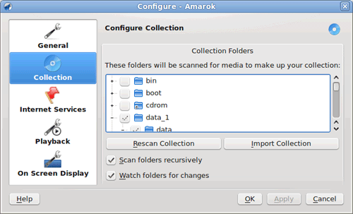
Figure 6-68. The Amarok music player configuration screen
Once Amarok finishes indexing, you can leave it active as an icon in the system tray. Accessing your music files and playlists requires only one click on the icon.
DVD Ripping
DVD Shrink (search the Web to find it)
DVDFab (http://www.dvdfab.com)
DVD rippers extract the program content from DVD-Video discs while removing copy protection, region coding, and other DRM measures. They may output the unprotected audio and video data as individual directories and files, or as a single ISO file ready to be burned to a DVD. Some DVD rippers offer you the option of producing discrete files or a single ISO file.
Because burnable dual-layer DVDs are relatively expensive and of questionable reliability, many DVD ripping applications offer you the option of compressing the original DVD material to fit an inexpensive standard 4.4 GB DVD±R(W) disc. The quality of the compression varies widely from one ripper to another and with the configuration of the ripper. Depending on the amount of data on a particular DVD-Video disc, the best rippers may produce compressed rips that are nearly indistinguishable from the original DVDs, even when viewed on an HDTV. Some rippers offer a high-quality mode, which does deep analysis of the data before compressing it for maximum quality, and a fast mode, which compresses the data as quickly as possible but with lower quality.
DVD rippers are commonly used in two ways.
First, and probably most common, is rent-rip-and-return (RRR), where the user rents a DVD-Video disc from Netflix, Blockbuster, or Redbox (or borrows it from the local public library), rips a copy of the video for his own collection, and returns the original disc. RRR drives the MPAA nuts, but there’s not much they can do about it. The more charitable term for RRR is time-shifting.
Second, many people rip their purchased DVD-Video discs to place-shift or format-shift the content. For example, they may rip videos to lower-resolution, highly compressed files that match the screen resolution and storage capacity of their cell phones. Or, as in our case, they may rip their DVD-Video discs to the hard drives of their media center systems.
Although there are several DVD ripping apps available for Linux, such as K9copy, none of them are as good as the corresponding Windows applications. Fortunately, that’s not a problem, because the best Windows DVD ripping applications install and run perfectly well under Ubuntu Linux.
The great-granddaddy of DVD rippers is DVD Shrink 3.2.0.15, shown in Figure 6-69, which was last updated in July 2004, just before the MPAA attack lawyers shut it down. Despite its age, DVD Shrink is still many people’s first choice of DVD rippers. It does what it does quickly and well. When set to use deep analysis for maximum quality, the resulting videos are often indistinguishable from the originals.
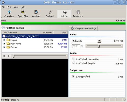
Figure 6-69. The DVD Shrink main screen
DVD Shrink is extremely easy to use. After you install it and configure it as you wish, you can simply put a protected DVD-Video disc in the drive and click Open Disc. DVD Shrink runs a quick preliminary analysis and then returns to the main screen. If you want to back up the DVD without any changes, simply click the Backup button and let ’er rip. If you want, for example, just the movie, you can click Re-author and eliminate unwanted structure elements.
You can also make some minor changes that may have major quality benefits. For example, you can opt to eliminate the soundtrack in alternate languages, rip only stereo sound rather than stereo plus 5.1 sound, or eliminate the director’s comments audio track. You can also choose to replace some useless video content (for example, coming attractions) with a simple placeholder image, which frees up space for the content you want to keep.
To install DVD Shrink under Ubuntu Linux, you must first install WINE (Wine Is Not an Emulator), a Linux package that allows many Windows programs to run under Linux. To do so, open the Ubuntu Applications menu and choose Add/Remove. In the Add/Remove Applications dialog, search for WINE. Mark the checkbox and click the Apply Changes button.
We can’t give you a URL to download DVD Shrink, but a quick Google search will turn up numerous download sites. Save the installer executable to your hard drive and double-click it to fire up the WINE installer. You can accept all the WINE installer defaults, except that we recommend you set the Windows type to Windows XP. When the installation finishes, you’ll be prompted to restart your system (which actually does a virtual Windows restart rather than restarting the Linux system). After the restart, DVD Shrink will appear in the Applications→WINE→Programs submenu. If you requested it during installation, there’ll also be a program icon on your desktop.
Although DVD Shrink works with nearly all DVD-Video discs, a few discs that were created after the final release of DVD Shrink use altered copy-protection methods that DVD Shrink can’t handle. The usual symptom is a “disc read error” message during the preliminary scan or the analysis pass. If that occurs, DVD Shrink can’t rip that DVD (although it can still be used to compress files ripped by a more recent ripper). You’ll need to rip the disc with a different ripper, such as DVDFab, shown in Figure 6-70.
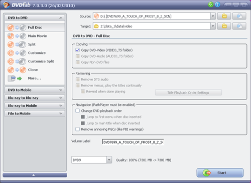
Figure 6-70. The DVDFab main screen
The most recent free version of DVDFab will almost certainly be able to rip any DVD-Video disc that DVD Shrink chokes on. (The pay version of DVDFab has many additional capabilities and is well worth considering.)
The free version of DVDFab operates only in file mode, ripping the contents of a DVD-Video disc to directories and files rather than to an ISO image file. Although the free version can compress these files to fit a 4.4 GB writable DVD, we’ve found that it’s better to rip the files uncompressed (using the 100% or DVD9 setting) and then run DVD Shrink against those files to produce a compressed ISO image file for later burning to disc.
To install DVDFab, download the latest installer from the website and save it to the hard drive. Double-click the installer file to fire up the WINE installer, and proceed as described for installing DVD Shrink.
Video Playback
VLC Media Player (Ubuntu repositories)
For watching videos, we need an application to turn our HDTV computer monitor back into an HDTV, without distracting elements like the task bar, menu, or mouse pointer visible. We also need all of the controls present on a DVD player—play, pause, next/previous chapter, and so on.
There are many video playback applications available for Linux, but for our purposes the VLC Media Player is the standout choice. Figure 6-71 shows the VLC control panel, which offers every control imaginable for playing back DVD and other video content.
Figure 6-71. The VLC control panel
Ubuntu does not install VLC by default. To install it, first make sure that you’ve installed the Ubuntu Restricted Extras package, which includes several of the codecs needed to display video in various formats. Then click the Ubuntu Applications menu and choose Add/Remove. When the Add/Remove Applications dialog appears, type “VLC” in the search box. Mark the VLC checkbox in the packages list and click Apply Changes to install VLC.
With one exception, the default configuration of VLC will probably be suitable. To modify VLC settings, click Tools on the VLC control panel and choose Preferences to display the Preferences dialog shown in Figure 6-72. About the only change you may want to make is to mark the Fullscreen checkbox to cause VLC to come up in full-screen mode by default for watching videos.
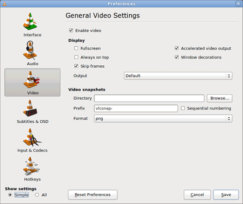
Figure 6-72. VLC Preferences dialog
Unless you change preferences, VLC displays video in windowed mode, as shown in Figure 6-73. You can toggle VLC output to full-screen mode from the VLC control panel Video menu. From full-screen mode, press the Escape key to return to the windowed display.
Figure 6-73. VLC windowed display output
Image Management and Editing
digiKam (Ubuntu repositories)
There are many image management and editing applications available for Linux, but we think digiKam (Figure 6-74) is the best choice. We use it primarily to index, annotate, manipulate, and edit our collection of thousands of digital camera images, but it’s also useful to manage and edit other images in nearly any format. (For example, we used it to manage the TIFF screen captures used in this chapter.)
Figure 6-74. digiKam splash screen
Ubuntu doesn’t install digiKam by default. To install digiKam, click the Ubuntu Applications menu and choose Add/Remove. When the Add/Remove Applications dialog appears, type “digiKam” in the search box. Mark the digiKam checkbox in the packages list and click Apply Changes.
When you fire up digiKam for the first time, the splash screen shown in Figure 6-74 appears, and persists until the program has finished scanning your hard drives. In our case, that took more than an hour, with the hard drives banging away the whole time. Of course, if you don’t have 12 TB of disk space and tens of thousands of image files, your wait will be shorter.
Once indexing completes, you can use digiKam to organize your images into albums, attach captions, tags, and ratings to each image, and so on. Figure 6-75 shows the main screen of digiKam as we began to attach captions and tags to some recently shot images.
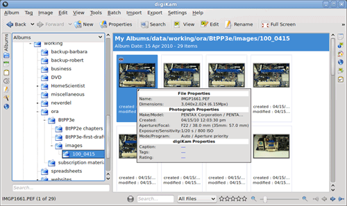
Figure 6-75. digiKam main screen
Indexing, annotating, and viewing image files is essential, but we also need the ability to edit and convert those image files. For example, as Robert was working on this section, Barbara handed him the DSLR she’d used to shoot images on a recent trip and asked him to download the RAW format image files she’d shot and convert them to JPEGs that she could have printed at Walgreens. No problem. For image editing, digiKam includes the professional-grade showFoto image editor, shown in Figure 6-76.
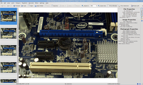
Figure 6-76. showFoto main screen
We’ve used a lot of image editors, and nothing else we’ve used comes close to the capabilities of showFoto. Like many well-designed applications, showFoto can be used on many levels, from easy cleanup and format/resolution conversions to very complex bit-level functions that we don’t completely understand. (OK, that we don’t understand at all.)
Camcorder Capture
Kino (Ubuntu repositories)
Transferring your camcorder video to the media center system may be as simple as connecting the camcorder to a USB port. If the camcorder is a USB mass storage device, Linux pops up a File Browser window that lists the video files on the camcorder. From there, just copy the files to the video directory on your hard drive. If your camcorder captures video to an optical disc, insert the disc into the optical drive and copy the files from File Browser to your hard drive.
If your DV camcorder uses the IEEE 1394 (FireWire) interface, you’ll need a separate program to transfer your video files. The best one we’ve found is Kino, shown in Figure 6-77. That’s Robert in our home lab, shooting an intro segment for one of his YouTube Home Scientist videos (http://www.youtube.com/user/TheHomeScientist).
FireWire if You Need It
The Intel DH55TC motherboard does not provide a FireWire interface. We captured that screen on Robert’s main system, where he does all the video transfers and heavy lifting. If you want FireWire support on your media center system, choose an ASUS, GIGABYTE, or Intel motherboard that provides it, or simply install an inexpensive FireWire adapter card.
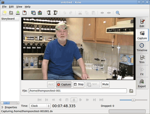
Figure 6-77. Kino capturing video footage from our DV camcorder
Kino requires FireWire support, which is not installed in Ubuntu by default. To install Kino and FireWire support, from the Ubuntu main menu choose System→Administration→Synaptic Package Manager. Search for “raw1394”. When the list of packages that contain that string appears, mark the checkbox for the libraw1394 library item and select it for installation. Then search for “Kino” and mark it for installation. Click the Apply button to install Kino and 1394 support. When the packages are installed, close Synaptic.
You may encounter the same problem we do with 1394 support. If you run Kino and attempt to capture DV footage, it may tell you that the file /dev/raw1394 is not available. The problem is that accessing that file requires root access. You can fix that problem as follows:
1. Close Kino.
2. Open a terminal window (Applications→Accessories→Terminal).
3. At the prompt, type cd /dev and press Enter.
4. At the prompt, type sudo chmod 777 raw1394 and press Enter (and type your password if prompted).
5. Close the terminal window and restart Kino.
The raw1394 library will be available until the system is rebooted. (Yes, this is a kludge, and there’s probably a better way to do it. If so, we don’t know what that is.)
Camcorder Video Editing
Cinelerra (http://cvs.cinelerra.org)
When we started shooting YouTube videos, we spent a long time checking out various Linux video editors. Kino includes video editing functions, but they’re limited and crude. We looked at several other editors, all of which had one or another fatal problem. Several friends and associates recommended we buy a Mac. Fortunately, we borrowed one first and played around with iMovie. We found that package so feature-poor that we considered it unusable, and the commercial alternatives for OS X or Windows cost much more than we were willing to pay.
Finally, we came across Cinelerra, shown in Figure 6-78. Cinelerra is a professional-grade video-editing program that’s similar in power and features to Adobe’s Premiere Pro or Apple’s Final Cut Pro but on a basic level is about as easy to use as Apple’s iMovie. After playing around with Cinelerra for an hour or two, we were able to do everything we could do with iMovie, and a lot more.
Easy Does It
Ubuntu recently added the video editor PiTiVi as a standard package. It’s considerably less powerful than Cinelerra, but it’s also easier to learn and may be all you need. Look for PiTiVi under the Applications→Sound & Video menu.
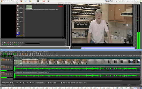
Figure 6-78. Using Cinelerra to edit one of Robert’s YouTube videos
The good news about Cinelerra is that it’s free, incredibly powerful, and (relatively) easy to learn to use. The bad news is that its interface is, uh, unusual. But you’ll get used to that quickly enough. The other bad news is that you’ll have to get your hands dirty to install it. It’s not included in Ubuntu, and it’s not available in the Ubuntu repositories. Cinelerra does, however, maintain its own repository, and it provides packages for current and recent Ubuntu releases.
For complete instructions on installing Cinelerra, point your web browser to http://cvs.cinelerra.org/getting_cinelerra.php#ubuntu.
Final Words
Now that we’ve finally done it, we can’t believe we waited this long to build a real media center system and connect it to an HDTV. For relatively little money, we now have all of our audio and video content centralized and easily accessible, not just in the den, but from anywhere in the house, and we no longer have to swap discs in and out.
Barbara has instant access to the Web and her email. (Robert still has a separate den system, so he can browse the Web or check email while Barbara watches a video.) Robert can kick back on the sofa and edit videos on a big screen with high-quality audio. In fact, all of the functionality of a general-purpose PC is always available, just one click away.
Of course, we seldom leave well enough alone. Here are some possible future upgrades we’re considering:
Security video
Among our planned projects is implementing a complete home video security system with TCP/IP webcams and Linux security video management software. We’ll set up webcams to monitor the exterior doors, home interior, and yard, and run monitoring and video stream recording software on the media center system. When someone rings the doorbell, one click will display the front-door webcam video/audio on the HDTV. We can even implement motion activation in software. When something changes significantly in a camera’s field of view, recording kicks in automatically.
We’ll set up a cron job to transfer video still sequences via our broadband connection to an off-site server in case we’re burgled and the media center system is stolen. To guard against a burglar smart enough to cut our cable, we’ll also set up cooperative arrangements with neighbors to transfer video still sequences by WiFi to their systems, and vice versa.
Home control
We played around years ago with X10 home control but found it to be unreliable. We may try again with a later technology, such as INSTEON or Universal Powerline Bus. If we do, the media center system will be an ideal central control system.
Weather station
Barbara is a weather junkie. We have a standalone weather station with remote sensors for temperature, rainfall, and so on. It records things like maximum/minimum temperature since the last reset, but what Barbara would really like is a logging system that tracks and records temperatures and other data very accurately and with fine granularity. The media center system is an ideal control center for this project.
Recording TV programs
Yeah, we know. After arguing that there are much better alternatives for recording television programs, here we are talking about maybe adding PVR functions in the future. For now, we’ll continue using our DVD recorder when we infrequently want to record OTA programs. But everything dies sooner or later, and when our current DVD recorder goes to that great electronics warehouse in the sky, we may decide it makes more sense to add a tuner card and PVR software to our media center system than to replace the DVD recorder.
These are just a few upgrade ideas. We’ll probably think of many more uses for our media center system, and we suspect those of you who build your own media center systems will do the same.