7. Building an Appliance/Nettop System
In a strict sense, we define an appliance system as a small, quiet computer that is dedicated to one task or a group of related tasks, such as a home server, a network-attached storage (NAS) box, a media center front-end, or a home-automation controller. In a broader sense, an appliance system may be a general-purpose computer that is particularly small, quiet, and unobtrusive. By that definition, the archetypal appliance systems are the Mac mini and the many models of ASUS Eee nettop systems and all-in-ones.
But we don’t have to buy a Mac Mini or ASUS Eee. We can build our own system based on a 6.7” square Mini-ITX motherboard with an AMD or Intel processor and run Windows 7 or Linux on it. Because we’re designing and building it ourselves, we can optimize our system for our own needs and budget.
For example, we can build an inexpensive, nearly silent appliance system with moderate performance around an Intel Atom motherboard and processor, or we can build a system with mainstream desktop performance around an Intel Core i3 or Core i5 processor. If we want both silence and high storage performance at the expense of storage capacity, we can install a fast, silent solid-state drive (SSD). If our priorities are low noise and high storage capacity at the expense of disk performance, we can install a quiet, high-capacity 5,400 RPM laptop drive. Or we can strike a happy compromise between noise level, capacity, and performance by installing a 7,200 RPM or faster laptop hard drive. Those aren’t options with the Mac mini or the ASUS Eee.
The point is, we can have it our way, and so can you. In this chapter, we’ll design and build the perfect appliance system for our needs. But your priorities may differ from ours, so we’ll also point out alternatives all along the way.
Determining Functional Requirements
The problem with determining functional requirements for an appliance system is that the appliance umbrella covers a huge range of systems. For example, we found 18 ASUS Eee models, ranging from a $230 nettop with a single-core Intel Atom CPU and no display to an $1,100 all-in-one model with a Core2 Duo processor and a 21” LCD display.
We can’t build an all-in-one system—one that embeds the motherboard and drives in the display—but that’s all to the good. With an all-in-one system, if one thing breaks, the whole computer is unusable while you ship it off for repair and wait for its return. With a separate system unit and display, it’s easy to repair or swap out the faulty component and have the system back up and running quickly.
By necessity, we had to choose specific components for our own appliance system. That allowed us to optimize it for our own requirements, but obviously your own priorities may differ. Accordingly, we specify numerous alternative choices, indicating the components that we might have used if we had been designing the appliance system for a different purpose.
We set our price goal at $350 without the display, external peripherals, or software—the same as for our budget system. The two systems are very different in their emphases, though. The appliance system makes small size and low noise the priorities at the expense of performance; the budget system emphasizes bang for the buck.
When we sat down to think through our own requirements for an appliance system, here’s what we came up with:
Size
We plan to use a Mini-ITX motherboard, so we looked at Mini-ITX cases in the 7-liter range (roughly the dimensions of a letter-sized sheet of paper, by about 4” high). That gives us room for a slim optical drive, one 2.5” hard drive bay with a spare bay for future expansion, and one or two half-height PCI and/or PCI Express expansion cards. A 7-liter case is about two-thirds larger in every dimension than a Mac mini case—about five times the volume—but still small enough to be unobtrusive.
Reliability
One of the major characteristics of any appliance is that it Just Works. When you click the button on the remote control, you expect your television or DVD player to power up every time, day after day, year after year. That’s a bit much to expect from any computer system, so our goal is reasonably high reliability.
Of course, the trade-off here is between reliability on the one hand and performance and cost on the other. We could design a system with extreme reliability by eliminating moving parts entirely—leave out the optical drive, use a passively cooled processor and power supply, use an SSD drive(s) rather than mechanical hard drives, and so on. By doing that, though, we’d also significantly increase costs, or decrease functionality and performance, or both. We decided to strike a happy medium here, shooting for high reliability without needlessly increasing costs or sacrificing performance and functionality.
Performance
We don’t expect our appliance system to be anywhere near as fast as a mainstream desktop system, but we do want enough horsepower to browse the Web, check email, watch YouTube videos, and so on—all without any noticeable sluggishness. In fact, a system with even half the processor and disk performance of the budget system would be more than adequate for our needs, both now and for the next few years. This system won’t have the performance needed for even undemanding 3D games, so integrated video will suffice.
Noise level
We want our appliance system to be unobtrusive, but that requires more than just small size. A small system that sounds like a leaf blower is an epic fail. Building a completely silent system is possible, but it involves too many cost, performance, and reliability trade-offs. We decided to aim for a system that was extremely quiet, but not completely silent. If system noise is not noticeable from two or three feet away, that’s sufficient.
Hardware Design Criteria
With the functional requirements determined, the next step was to establish design criteria for the appliance PC hardware. Here are the relative priorities we assigned for our appliance PC. Your priorities may, of course, differ.
|
Price |
★★★✩✩ |
|
Reliability |
★★★★✩ |
|
Size |
★★★★✩ |
|
Noise level |
★★★★✩ |
|
Expandability |
★✩✩✩✩ |
|
Processor performance |
★★✩✩✩ |
|
Video performance |
★✩✩✩✩ |
|
Disk capacity/performance |
★★✩✩✩ |
Our appliance system configuration is heavily skewed toward reliability, size, and noise level, with other elements taking a backseat. Here’s the breakdown:
Price
Price is moderately important for this system, as we’ll use it only as a supplemental system. We’re willing to spend about the same amount we did for the higher-performance budget system. Obviously, if this were to be a primary system, we’d boost the budget significantly.
Reliability
Reliability ties for top importance with size and noise level. We’ll make minor compromises in cost, performance, or features to make this system as reliable as possible without taking any of the extreme measures described in the preceding section.
Size
Size is another high priority. We don’t need a truly tiny system, but we want something that will fit comfortably and unobtrusively on Robert’s end table, either nestled in under the LCD display’s bezel or perhaps sitting under its base.
Noise level
Noise level is as important as reliability and size. That means we’ll need a passively cooled processor and a notebook hard drive. If the system has any fans, we’ll want them to run at very low speed while still providing adequate cooling.
Expandability
Expandability is unimportant for our appliance system. We may at some point want to make some minor system upgrades, such as adding an expansion card or more memory and perhaps a second hard drive, if we have a free bay. To the extent that we can provide for such future expansion without compromising higher-priority considerations, we’ll do so. But we consider expandability as tied with video performance for dead last in priority.
Processor performance
Processor performance is relatively unimportant for our appliance system. Minimizing noise in a small case just about requires a passively cooled processor, like some of the Intel Atom models. We’d like a dual-core processor with a CPU Mark score of 500 or higher, but we wouldn’t rule out a single-core unit if it meets our needs better than the available dual-core models.
Video performance
Video performance is tied with expandability for the lowest priority. We want integrated video good enough to drive the display we choose at its optimum resolution. Other than that, we’ll make no demands of the video subsystem.
Disk capacity/performance
Disk capacity and performance are relatively unimportant, in the same category as processor performance. Size and noise constraints mean we’ll have to use a 2.5” notebook hard drive rather than a 3.5” desktop unit. We’d like a 1 TB 7,200 RPM drive, but that’s not an option in this size range. We’ll choose a higher-capacity 5,400 RPM drive rather than a small-capacity 7,200 RPM unit. The extra speed would be nice, but the higher capacity is a bigger priority for us.
Brian Bilbrey Comments
If this system has a home server to pull files from, a smaller, faster drive might be much better, or even a small, inexpensive SSD just for the OS, with all data stored on the server.
Component Considerations
If you’ve ever built a standard PC, you’ll probably be surprised when you first see just how small all the components for an appliance system are. Mini-ITX motherboards are much smaller than what you’ll be used to. Drives look like they’ve shrunk in the dryer. The largest Mini-ITX cases are small, and the smallest are tiny.
All of this may have a major impact on your system design and build. You’ll have to verify, for example, that your optical drive fits your case. You’ll probably use a slim (quarter-height) optical drive, but you may find that not just any slim drive will do. The depth of a particular slim optical drive may be greater than the case will accommodate.
Similarly, the motherboard layout may assume much more significance than it has in an ATX or even μATX system. For example, the main ATX power cable from your power supply may be too short to reach the connector on the motherboard, or parts of the case frame may block access to motherboard connectors. The standard CPU cooler you planned to use may be too tall to fit the case, and so on.
Sometimes, there’ll be an easy solution. You may, for example, be able to connect a front-panel USB cable to a different set of motherboard USB header pins than you planned to use, or you may be able to bend something just slightly, enough to give you clearance to plug in a cable or drive in a screw. But sometimes a particular component just can’t be made to work in a particular case, which is why it’s important to do your homework.
Before you actually order any component, check the website for detailed specifications—things like component height or mounting hole positions. Study a high-resolution image of the motherboard and match it up against the case you intend to use. You may find that an essential motherboard connector is blocked by the bottom of the power supply or that some of the components near the edge of the motherboard are too tall to fit under the edge of an intruding part of the case frame.
In short, you have to take much more care in choosing components for a Mini-ITX system than you do with larger systems. (We actually built our appliance system using the components we recommend, but we didn’t build systems around our suggested alternatives, so you’ll need to check carefully for yourself.)
Even if you’re careful to choose only components that fit the case, you may find that building the system is more involved than you expected. With larger systems, you can usually install components in nearly any order that makes sense to you. With a Mini-ITX system, you may have to install components in one particular order, because installing one component may block the access you need to install another component.
If you use components other than those we actually used to build the system illustrated here, don’t be surprised if you have one or two false starts. That happens to us more often than not when we build a tiny system with components that we haven’t used before.
Worst case, you may get the whole system assembled before you realize that you forgot to install a cable whose motherboard connector is no longer accessible. So you remove the drives and bays, disconnect everything until you have access to the hidden connector, connect that cable in the proper sequence, and rebuild the rest of the system. You may spend an extra half-hour building the system and curse yourself for not getting it right in the first place, but that’s just part of building tiny systems.
With those cautions kept firmly in mind, here are the components we chose for our own appliance system.
Case and Power Supply
Antec ISK 300 Mini-ITX case (http://www.antec.com)
When we wrote the preceding edition, Mini-ITX products were available but had not yet become mainstream. In particular, the selection of suitable Mini-ITX cases was extremely limited. But Mini-ITX “arrived” in 2009, and a wide selection of Mini-ITX motherboards and cases is now readily available.
Mini-ITX cases range in volume from about 1.8 liters (a smidgen larger than a Mac mini) to 15 liters (a bit smaller than a basketball). Most mainstream Mini-ITX cases are either flat (“book-style”) or cubic, but models are also available for rack-mounting or installing in vehicles.
Some Mini-ITX cases, such as the Antec 300-150, have a built-in power supply that connects to a standard AC wall receptacle. The power supply provides the usual power cables for the motherboard and drives, just as in a standard ATX system. Other Mini-ITX cases, such as the Antec 300-65, use an external power brick that provides low-voltage DC current to a jack on the case. That jack connects to a circuit board inside the case, which provides the usual power cables for the motherboard and drives.
Cases with an internal power supply (usually) have higher output, and may be necessary if you use a relatively fast processor (such as an Intel Core 2 Duo or 45W AMD Athlon) rather than an Intel Atom—or if you install a high-current video adapter or multiple 3.5” hard drives. Conversely, cases that use an external power brick are (usually) cooler-running and quieter overall and may provide an extra drive bay without increasing the case volume. They are also usually somewhat less expensive.
Book-style cases are generally less obtrusive and more space-efficient, particularly if you intend to use a passively cooled processor such as an Intel Atom. The greater height of a cube or shoebox case may be required if your processor requires active cooling or if you intend to install a full-size video adapter. Another benefit of these somewhat larger cases is that many accept standard-size optical drives and 3.5” hard drives, which broadens your options and cuts your costs.
Among the book-style cases, our first choice is the Antec ISK 300, which is available with a 150W internal power supply or a 65W power brick. The only minor fault we noticed with these cases is that the side cooling fan is noisier than we’d like. Even with the fan running at low speed, the hum is audible to us if the system is less than a meter away. Most people probably wouldn’t consider the fan noise objectionable, but if you do you can easily replace the case fan with a $10 aftermarket fan that’s much quieter.
If you’re building a Mini-ITX home theater system, you may prefer the Thermaltake RSI H SD100. If you want to use a mainstream processor and standard-size optical and hard drives, our pick is the Thermaltake Element Q VL52021N2U, which includes a 200W SFX power supply. If we were building a “pocket battleship” Mini-ITX system with a fast processor and high-performance graphics card, we’d choose the Silverstone Sugo SG05-B, which includes a 300W power supply and can accept a RADEON HD 4850 graphics card.
Processor, CPU Cooler, and Motherboard
Intel D510MO (http://www.intel.com)
Depending on the processor you choose, the CPU performance of your appliance system may vary by an order of magnitude or more. At one extreme, you can build your appliance system around a processor like the Intel Core i5 and achieve performance that matches that of all but the fastest desktop systems. At the other extreme, you can choose a processor like the dual-core Intel Atom D510, which is much slower but also much less expensive and much cooler-running.
The Intel D510 Atom is slow only in comparison to more expensive recent processors, though. To put the performance of the D510 Atom in perspective, it’s faster than high-performance processors from just a few years ago, such as the AMD Athlon 64 4000+ and the 3.8 GHz Intel Pentium 4. Millions of people still use systems with those older, slower processors and are perfectly content with their performance.
Before you decide on a processor, decide just how much performance you really need. It’s tempting to build a faster appliance system than you really need, but the downsides of doing that are that your fast appliance system will be larger, noisier, and more expensive.
For a typical appliance system, we think the best choice is an Intel Atom D510 processor on an Intel D510MO motherboard. That combination is fast enough to handle routine tasks under Linux or Windows. The integrated Intel Graphics Media Accelerator 3150 (GMA 3150) video is not fast enough for full-HD video playback, but it is fast enough for SD video and has excellent display quality for typical general computing tasks. (We do wish the D510MO included a DVI or HDMI output rather than just analog VGA, but that’s acceptable for our purposes.) The processor and video together draw a maximum of only 13W, which means the system can use passive cooling. The motherboard meets Intel’s usual quality, compatibility, and reliability standards, which are extremely high. And the whole shebang—motherboard with processor installed—costs well under $100.
Other than the analog-only video port, our only criticism of the D510MO is that it includes only two SATA connectors, which limits us to one hard drive and one optical drive. Or so it seems at first glance. In fact, we could install an optical drive just long enough to install the operating system and then remove it and substitute a second hard drive. Alternatively, we could install a half-height PCI or PCI Express expansion card to get additional SATA ports.
The GIGABYTE GA-D510UD is another excellent choice. It’s very similar to the Intel D510MO, but costs $10 or so more. For that extra money, you get an added standard ATA port and two more SATA ports. GIGABYTE (along with ASUS) makes first-rate motherboards, and we might actually have chosen this board if it had been the same price as Intel’s offering or if it had included a DVI/HDMI video output. But in our experience it’s tough to beat Intel motherboards for quality, stability, and reliability, so we happily selected the Intel D510MO.
Of course, you may need more horsepower—CPU, video, or both—than the D510MO provides. Here are some options:
- If processor performance is adequate but you need better video performance, choose an ASUS or GIGABYTE D510 Atom motherboard that uses embedded NVIDIA 8xxx/9xxx-series or ION video. Those boards are more expensive than the D510MO, but their embedded video is more than adequate to handle full-HD video streams, such as for Blu-ray playback. Alternatively, look for an ASUS or GIGABYTE Atom motherboard that includes a PCI Express x16 expansion slot and install a standalone video adapter. Of course, that means you’ll probably also need a larger case and power supply.
- If you need better processor performance, buy the Intel DH57JG, which supports fast Intel Core i3 and Core i5 processors, includes integrated Intel HD graphics, and provides a PCI Express x16 expansion slot. Once again, you’ll probably want to choose a cube- or shoebox-style case with an internal power supply of 200W or more.
Why no AMD products? In our opinion, the Intel platforms are simply a much better choice for any appliance system, and we don’t see that changing any time soon.
Memory
Crucial CT2KIT12864AA800 PC2-6400 Kit (2 GB×2)
(http://www.crucial.com)
The Intel D510MO motherboard has two DDR2 memory slots and supports dual-channel memory operation with PC2-5300 or PC2-6400 modules in capacities up to 2 GB, for a maximum of 4 GB. At the time we built this system, PC2-6400 CL6 modules sold for the same price as PC2-5300 CL5 modules. Even with one extra wait-state, the PC2-6400 memory is slightly faster, so that’s what we installed.
We might have gotten away with installing only 2 GB of memory in this system, but the 4 GB memory kit cost only about $40 more than the 2 GB kit. We decided that a system with a low-power processor and 5,400 RPM hard drive could really use a bit of extra help, so we decided to install a 4 GB memory kit. We chose a compatible 4 GB memory kit from Crucial because we’ve never had a problem with Crucial memory.
Video Adapter
Integrated Video
The Intel D510MO motherboard includes integrated GMA 3150 video, which is sufficient for our needs. If we required more integrated graphics power, we’d have chosen an Atom motherboard that included integrated NVIDIA 8xxx/9xxx-series or ION video. If we required still more graphics horsepower, we’d have chosen an Atom motherboard with a PCI Express x16 slot and installed a midrange video adapter, such as an ATI RADEON HD 4xxx-series card.
Primary Storage
Seagate Momentus 5400 ST9640320AS (640GB) (http://www.seagate.com)
This section was originally titled “Hard Drive,” but an appliance system doesn’t necessarily use a traditional 3.5” hard drive, or even a 2.5” laptop hard drive. Nowadays, a solid-state drive (SSD) is an affordable option. Each of those three types has advantages and disadvantages.
A typical 3.5” 7,200 RPM desktop hard drive can have a capacity of 2 TB or more and, at roughly $0.10/GB, has by far the lowest cost per gigabyte of any of these drive types. Read and write speeds are both high, as is reliability. Most book-style Mini-ITX cases are too small to have a 3.5” drive bay, and we rejected those few that did for other reasons. Some cube-style Mini-ITX cases provide one 3.5” drive bay, and a few provide two or more. If the case you choose has a 3.5” drive bay and you require significant storage capacity, installing a quiet desktop 3.5” hard drive is by far the most cost-effective decision.
Nearly all Mini-ITX cases include one or more 2.5” drive bays. Mainstream 2.5” laptop hard drives are available with capacities up to 1 TB and rotation rates from 4,200 to 7,200 RPM. A few 10,000 and 15,000 RPM models are available, but their prices are outrageous, their capacities small, and their heat production and noise prodigious. The price, capacity, and performance of laptop hard drives are closely interrelated: the largest drives are expensive and slow, the fastest drives are expensive and small, and the least expensive drives are small and slow.
A typical laptop 2.5” hard drive has half the capacity of a 3.5” desktop hard drive that costs the same, and runs at 5,400 rather than 7,200 RPM. You pay that premium for the smaller physical size and lower power consumption. Read and write speeds are closely matched and vary from moderate to high depending on the type of drive. Laptop hard drives have a reputation for unreliability compared to desktop hard drives, but in all fairness that’s probably because they are typically used in poorly ventilated laptop systems that are much more likely than desktops to be dropped or shocked. If the case you choose does not accept a 3.5” hard drive, the most cost-effective choice is a 2.5” hard drive in whatever combination of capacity, performance, and price is best for your needs.
Solid-state drives debuted in consumer systems as very expensive options for high-end notebook systems, but they are becoming increasingly common in Mini-ITX systems. Their advantages are obvious: high performance, low power consumption (and heat production), and completely silent operation. SSDs are available in many form factors, including some units that can be installed in a PCI slot, leaving a drive bay available for another drive.
With the exception of their very high price per gigabyte, the disadvantages of SSDs are less obvious, but worth considering. First and foremost, SSDs wear out as they are used. Consumer-grade multi-level cell (MLC) SSDs are generally rated for one to two million write cycles (1,000 to 10,000 writes per cell) and professional-grade single-level cell (SLC) SSDs for about five million write cycles (100,000 writes per cell). Even with wear-leveling enabled and a large allocation of spare sectors, the capacity of any SSD gradually decreases with use as more individual cells become unusable.
The performance of SSDs is a mixed bag. Excluding the least expensive models, a new SSD generally offers noticeably faster read performance than a hard drive. In particular, random reads are much faster because there are no heads to be moved and zero latency. Writes are much slower than reads, however, and write performance declines as the drive ages, even if the operating system fully supports TRIM (as do Windows 7 and recent Linux releases). In some cases, write performance may degrade sufficiently to cause the system to appear to hang for a second or more while a write is completed.
Finally, although it’s not an issue for most people, it’s impossible to securely wipe an SSD. Well, at least if you expect the drive to be usable after it’s wiped.
Balancing all of these factors, we decided that a 2.5” laptop hard drive was the best choice for our appliance system. We’d budgeted about $100 for primary storage. That would have bought us a 1 TB or larger 7,200 RPM 3.5” desktop hard drive, but alas, we had no room for a 3.5” drive. For $100 we could have purchased a 32 GB MLC SSD, but that was simply too little storage space. So we looked at 2.5” laptop hard drives. The 5,400 RPM 640 GB Seagate ST9640320AS Momentus was selling for about $90, and the 7,200 RPM 320 GB Seagate ST903203N3A1AS Momentus for $20 more. We decided on the larger, slower model, but on another day we might just as easily have chosen the smaller 7,200 RPM drive.
Optical Drive
LiteOn DS-8A4S Slim Internal DVD Burner (http://www.liteonit.com)
One of the drawbacks of using a small Mini-ITX case is that few of them, including the one we chose, have room for standard optical drives. That meant we needed a “slim” DVD burner. Compared to standard units, the selection of such drives is quite limited, the prices are higher, and the durability is lower. Still, the only alternative would have been to use a different case, and that we didn’t want to do.
Slim internal DVD burners are available in slot-load and tray-load models. Our experience with slot-load drives from numerous manufacturers has been uniformly terrible. (We once had to tear down a system and remove and disassemble the optical drive to reclaim the DVD it had eaten, which was a friend’s only backup copy.) Ruling out slot-load models left us with several tray-load models to consider. Of those, we ruled out Sony and LG models because our experience with slim drives from those manufacturers has been less than good. That left us with the LiteOn DS-8A4S drive, which we purchased.
External Peripherals
We’re going to wimp out here. It’s not that we don’t want to list recommended external peripherals for the appliance system. It’s that we can’t, because the best external peripherals for our appliance system probably won’t be the best for your system. Accordingly, all we can recommend is that you choose external peripherals according to your budget and the purpose of your system.
Our appliance system will replace Robert’s current den system, a mini-tower unit. Yes, we also have a media center system with a 42” HDTV display in the den, but Robert may want to do something else while Barbara re-watches Brideshead Revisited. Of course, Barbara may want to do something else while Robert watches Firefly or Buffy the Vampire Slayer (for the fourth or fifth time), but she doesn’t want a computer and display on her end table.
Component Summary
Table 7-1 summarizes our component choices for our appliance system.
|
Table 7-1. Bill of materials for appliance system |
|
|
Component |
Product |
|
Case |
Antec ISK 300-150 Mini-ITX case w/150W power supply |
|
Motherboard |
Intel D510MO |
|
Processor |
Intel D510 Atom (installed on motherboard) |
|
CPU cooler |
(Installed on motherboard) |
|
Memory |
Crucial CT2KIT25664AA800 PC2-6400 4 GB Kit (2 GB×2) |
|
Video adapter |
(Integrated) |
|
Hard disk drive |
Seagate ST9640320AS Momentus 5400 (640 GB) |
|
Optical drive |
LiteOn DS-8A4S Slim Internal DVD Burner |
Building the Appliance System
Figure 7-1 shows the internal components of the appliance system. (Yep, that’s the same image we used on the cover.) The Intel D510MO motherboard sits atop the Antec ISK300-65 case, with the Crucial 4 GB memory kit to its left. At the bottom right are the LiteOn slimline DVD writer and the Seagate Momentus 2.5” hard drive. That’s everything. Not many components, but that’s all it takes to build our appliance system.
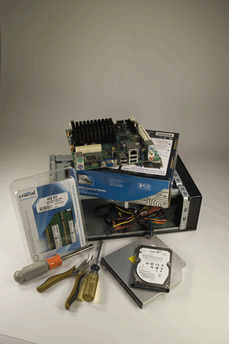
Figure 7-1. Appliance system components, awaiting construction
What’s Wrong with This Picture?
OK, we admit it. We compromised our technical integrity to get a prettier cover image. We figured we’d better ’fess up now, before one of our sharp-eyed readers noticed the glaring mistake in this image and called us to account. Yes, that’s a 7 mm Sears Craftsman nut driver, which we chose for its pretty orange handle. We’ve used cases that require a 5 mm or 6 mm nut driver, but never a 7 mm one. And we didn’t actually need a nut driver for this system, anyway.
If this is your first system build, it might take you an hour or so. If you’ve built systems before, you’ll probably have it ready to boot up in only 10 or 15 minutes. Before you proceed, make sure you have everything you need. Open each box and verify the contents against the packing list. Make sure the I/O shield and all driver discs, cables, screws, and other small components are present.
Order Is Important
When you build a standard desktop or tower PC, the exact component installation sequence usually doesn’t matter much. With an appliance system, that’s often not true. The small case means there’s little room to work in. One component may be inaccessible after you’ve installed another component. If you forget to connect a cable to the motherboard, for example, you may later have to partially disassemble the system to get to it.
The Antec ISK300 case is much better than most small cases in this respect. The integrated top and side panels slide off as a unit, which means the interior is quite accessible, albeit a bit cramped in places. If you’re using a different case, it’s worth spending some time thinking through the installation order before you actually start connecting things. Otherwise, you may have to tear everything down and start again.
As you build your system, pay particular attention to cable routing. As you connect cables, make sure you route them along and around frame components so that it will be possible to dress and tie off the cables neatly to avoid restricting air flow or fouling the fan.
Preparing the Case
To begin preparing the Antec ISK300-65 case, remove the three thumbscrews that secure the cover, as shown in Figure 7-2. (On our case, the thumbscrews were tight enough that we needed a screwdriver to loosen them.)
After you remove the thumbscrews, slide the cover back about a third of the way and then lift the cover straight off, as shown in Figure 7-3.
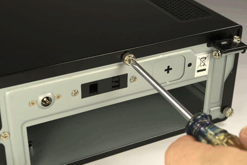
Figure 7-2. Remove the three thumbscrews that secure the cover
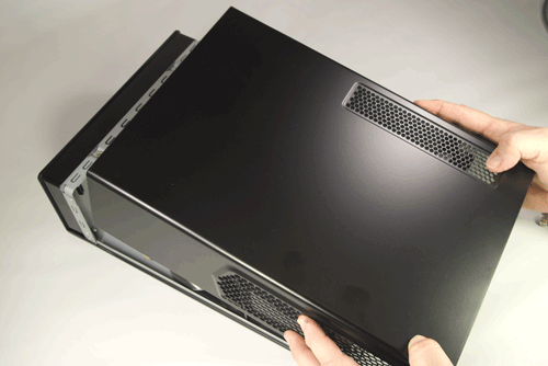
Figure 7-3. Slide the cover back about a third of the way and lift it off
The next step is to remove the drive tray assembly. To do so, remove the three Phillips screws—one at the center rear and one each at the left and right front—that secure it to the chassis frame, as shown in Figure 7-4. Grip the middle of the tray, as shown in Figure 7-5, and slide the tray toward the rear of the chassis until it comes free. Lift the drive tray clear of the chassis and put it aside.
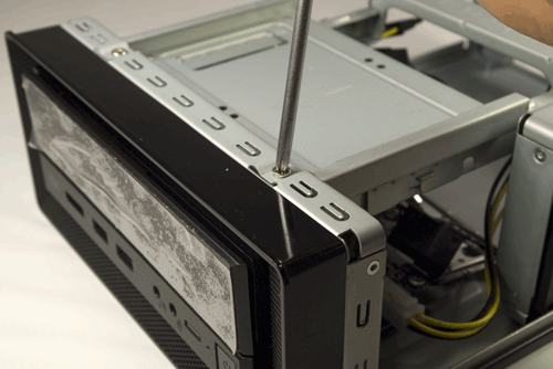
Figure 7-4. Remove the three Phillips screws that secure the drive tray to the frame
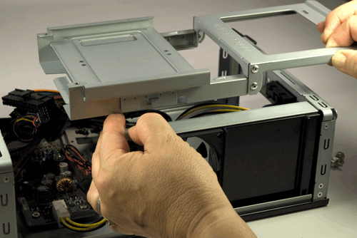
Figure 7-5. Slide the drive tray back and lift it off
With the drive tray removed, the inside of the case is visible. If you’ve spent any time inside a PC before, the first thing you’ll probably notice is that there are lots of power supply wires, but no power supply. That circuit board at the lower front of the case accepts 19VDC from the power brick and converts it to the voltages needed by the system components.
You’ll also notice a thin metal I/O shield, which you can put aside for later disposal. Nearly every case we’ve used, including the Antec ISK300-65, includes a generic I/O shield whose holes never seem to match the port arrangement on any motherboard ever manufactured on planet Earth. We’re not sure why case manufacturers include these worthless bits of metal.
But we do need to install an I/O shield, both to block dust from entering the large hole that would otherwise be present and to make sure the case provides proper ventilation to the processor and chipset. Open the motherboard box and locate the I/O shield provided with the motherboard. Before you proceed, place that I/O shield against the back panel of the motherboard, as shown in Figure 7-6, to verify that the holes in the template match the ports on the motherboard. (You might think the template and motherboard are guaranteed to match, since they came in the same box. Not always. We’ve found mismatched I/O shields supplied with more than one motherboard, including some from first-tier manufacturers.)
Once you’ve done that, install the custom I/O shield. Working from inside the case, align the bottom, right, and left edges of the I/O shield with the matching case cutout. When the I/O shield is positioned properly, begin on one corner and press gently along the edges to seat it in the cutout, as shown in Figure 7-7.
![]() You Can’t Get There from Here
You Can’t Get There from Here
If you’re using the Antec ISK300-65 case and Intel D510MO motherboard, jump forward and read the section on seating and securing the motherboard before you actually install the I/O shield.
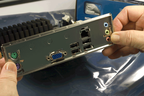
Figure 7-6. Verify that the I/O shield matches the motherboard rear-panel ports
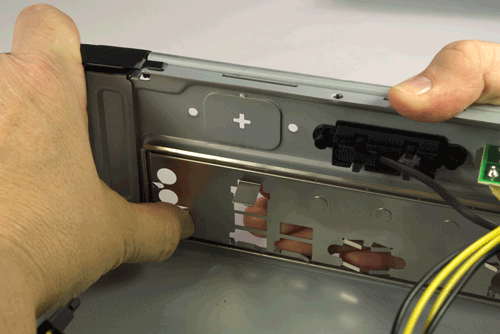
Figure 7-7. Position the I/O shield and snap it into place
The I/O shield should snap into place, although getting it to seat properly sometimes requires several attempts. As you apply pressure from inside the case against the template, use your finger to apply offsetting pressure on the outside of the template to avoid bending it. If you can’t get it to snap into place using finger pressure alone, use the handle of your screwdriver to press along the edges until you feel it seat.
Be careful not to bend the I/O shield when you seat it. The template holes need to line up with the external port connectors on the motherboard I/O panel. If the template is bent even slightly it may be difficult to seat the motherboard properly. After you seat the I/O shield, temporarily place the motherboard in position to verify that the back-panel I/O ports on the motherboard align properly with the corresponding holes in the I/O shield.
Once you’re sure the I/O shield is installed and aligned properly, hold the motherboard over the case, aligned and positioned as it will be when it is installed in the case. Look down through each motherboard mounting hole to locate the mounting positions on the base of the case. The goals are to make sure that there is a standoff installed that corresponds to each motherboard mounting hole, and that no extra standoffs are installed.
See the Light
If you simply look at the motherboard, it’s easy to miss one of the mounting holes in all the clutter. We generally hold the motherboard up to a light, which makes the mounting holes stand out distinctly.
![]() Check and Double Check
Check and Double Check
If your case comes with preinstalled standoffs, make absolutely certain that each standoff matches a motherboard mounting hole. If you find one that doesn’t, remove it. Leaving an “extra” standoff in place may cause a short circuit that could damage the motherboard and/or other components.
If necessary, install and/or remove standoffs until each motherboard mounting hole has a standoff and each standoff has a motherboard mounting hole. You’ll probably be able to use your fingers to install or remove standoffs. If the fit is too tight for finger pressure alone, use needlenose pliers.
Once you’ve installed and/or removed the standoffs required to match the motherboard mounting hole configuration, do a final check to verify that (a) each motherboard mounting hole has a corresponding standoff, and (b) no standoffs are installed that don’t correspond to a motherboard mounting hole.
The Intel D510MO motherboard has four mounting holes. The Antec ISK300-65, like many cases, ships with several standoffs preinstalled. All four of the standoffs preinstalled in the ISK300-65 corresponded with mounting holes on the D510MO motherboard, so we didn’t need to install or remove any standoffs.
Place the prepared case aside for now.
Installing Memory
The D510MO motherboard comes with the Atom processor and CPU cooler preinstalled, so all we need to do to prepare the motherboard is install the memory modules.
![]() Avoid Static Shock
Avoid Static Shock
Before handling memory modules or other static-sensitive components, first touch the chassis frame to ground yourself.
Installing memory in the Intel D510MO motherboard is straightforward. We have two memory modules to install, and two memory slots available.
To begin, ground yourself. Place the antistatic wrapper from the D510MO motherboard on a flat surface, and place the motherboard atop the wrapper. Pivot the white plastic locking tabs on both sides of both DIMM sockets outward to prepare the slots to receive DIMMs, as shown in Figure 7-8.
Orient the first DIMM with the notch in the contact area of the DIMM aligned with the raised plastic tab in the DIMM socket and slide it into place, as shown in Figure 7-9.
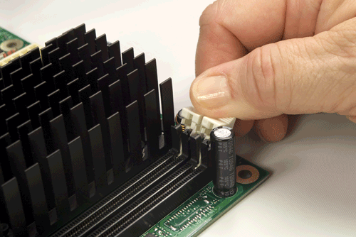
Figure 7-8. Pivot the DIMM slot locking tabs outward to prepare the slot to accept a DIMM
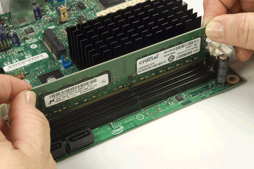
Figure 7-9. Orient the DIMM with the notch aligned properly with the socket
With the DIMM properly aligned with the slot and oriented vertically relative to the slot, use both thumbs to press down on the DIMM until it snaps into place. The locking tabs should automatically pivot back up into the locked position, as shown in Figure 7-10, when the DIMM snaps into place. If they don’t, close them manually to lock the DIMM into the socket, as shown in Figure 7-11.
Repeat this procedure for the second DIMM. With the memory installed, you’re almost ready to install the motherboard in the case. Before you do that, check the motherboard documentation to determine if any configuration jumpers need to be set. The Intel D510MO has only one jumper, the BIOS Setup configuration jumper, which sets operating mode. On our motherboard, that jumper was set correctly to Normal (pins 1 and 2 jumpered) by default, so we proceeded to the next step.
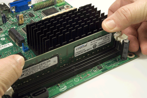
Figure 7-10. Seat the DIMM by pressing firmly until it snaps into place
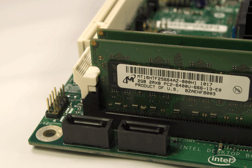
Figure 7-11. Make sure the latches engage the notches on the DIMM to lock the DIMM into place
Installing the Motherboard
Installing the motherboard is the most time-consuming step in building the system because there are so many cables to connect. It’s important to get all of them connected right, so take your time and verify each connection before and after you make it. Figure 7-12 shows the positions of the major components and connectors on the Intel D510MO motherboard. Refer to this diagram as you install the motherboard and connect the cables.
![]() Neatness Counts
Neatness Counts
Before you install the motherboard, tie off the front-panel and other cables to keep them out of the way. The limited working space inside a small case makes it easy to lose track of a cable and later find that it’s caught underneath the mounted motherboard and can’t be pulled free because the connector jams it in place.
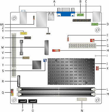
Figure 7-12. Positions of major components and connectors on the Intel D510MO motherboard (image courtesy of Intel Corporation)
Here’s the key:
A – Back-panel connectors
B – Serial port header (COM1)
C – Parallel port header
D – Serial port header (COM2)
E – LVDS inverter power voltage selection jumper (optional)
F – Chassis fan header
G – Power connector (2×12)
H – LVDS inverter power connector (optional)
I – Standby power LED
J – Intel Atom processor
K – LVDS inverter voltage selection header (optional)
L – DIMM channel A socket, DIMM 0
M – DIMM channel A socket, DIMM 1
N – LVDS panel connector (optional)
O – SATA connector 1
P – SATA connector 0
Q – Front-panel header
R – Battery
S – Front-panel wireless activity LED header
T – Intel NM10 Express Chipset
U – Front-panel USB header (with Intel Z-U130 USB Solid-State
Drive (or compatible device) support
V – PCI conventional bus connector
W – PCI Express x1 Mini Card connector
X – USB front-panel header
Y – Front-panel audio header
Z – BIOS setup configuration jumper block
AA – S/PDIF header
Seating and securing the motherboard
Particularly with Mini-ITX cases, clearances may vary from adequate to tiny to nonexistent. You may find it’s simply impossible to get everything assembled without making a minor case mod or two, temporary or permanent. With various small cases and motherboards, we’ve had to do everything from temporarily bending something out of the way to enlarging an access hole with our Dremel Moto-Tool to supergluing the I/O shield to the back of the case.
We encountered just such a situation with the Antec ISK300-65 case and the Intel D510MO motherboard. We should emphasize that the problem was really neither Antec’s nor Intel’s fault. Although the Mini-ITX specification is well defined, when you’re working in three dimensions with small clearances, there’s enough slop in the specification to allow some problems to occur. A different Mini-ITX motherboard might have fit the ISK300-65 case with no problems; the D510MO motherboard might have fit a different Mini-ITX case without problems. Unfortunately, the only way to know for sure if a particular combination of motherboard and case will go together smoothly or require minor case mods is to try it.
In our situation, the problem was a lack of clearance caused by a combination of the metal port enclosure (labeled H949d in Figure 7-13) on the D510MO motherboard that contains the keyboard and mouse PS/2 ports, and a projecting black plastic expansion connector that joins part of the ISK300-65 case to the frame, just to the right of the H949d enclosure.
With the I/O shield in place, there was simply no way to slide the motherboard into position, because we couldn’t slide the H949d enclosure past that protruding expansion connector. We considered temporarily removing the assembly secured by the expansion connector and then reinstalling it after the motherboard was in place, but that looked to be more work than it was worth.
So we decided to use our butt nippers to nibble off excess plastic from the offending expansion connector, as shown in Figure 7-14. That, of course, required removing the I/O shield.
Don’t Cut Too Much
Remove only excess protruding plastic; leave enough of the connector to keep the subassembly secured. If you don’t have butt nippers, you can use a sharp knife or single-edge razor blade to remove the excess plastic.
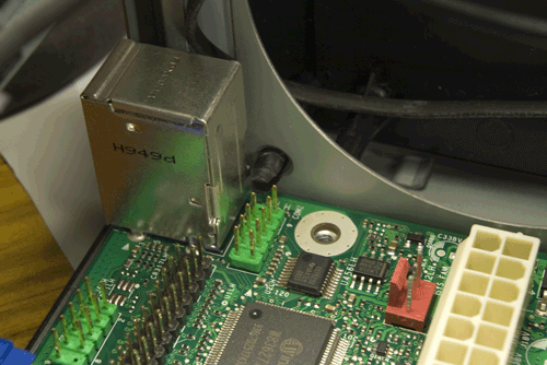
Figure 7-13. Motherboard installation blocked by a protruding connector
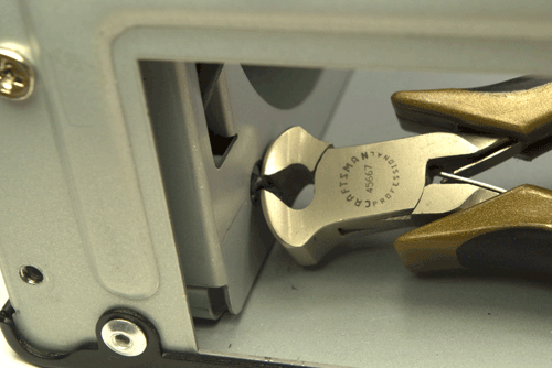
Figure 7-14. Use butt nippers to nibble off excess plastic from the offending projection
Slide the motherboard into position, carefully aligning the back-panel I/O connectors with the corresponding holes in the I/O shield. Once the motherboard is in position, examine the rear I/O panel carefully to make sure that none of the grounding tabs are protruding into jacks.
Sometimes You Need a Shoehorn
I/O shield grounding tabs, particularly those for Ethernet and USB jacks, have a nasty tendency to foul the jacks they’re designed to ground. In some cases, the problem is obvious at a glance, because the grounding tab actually covers the jack. In other cases, the problem is easy to miss unless you look carefully, because the tab intrudes into the jack. Ron Morse notes that a bright flashlight is helpful to make it easy to see an errant grounding tab.
Sometimes there’s no alternative but to bend the offending grounding tab out of the way until you’ve installed the motherboard. If you have to do that, use the tip of a screwdriver to bend the grounding tab back into contact with the body of the jack after you’ve seated the motherboard and installed the screws to secure it.
Keep pressure on the motherboard to align the standoffs with the corresponding mounting holes, and drive screws into all four standoffs to secure the motherboard in place, as shown in Figure 7-15. Tighten the screws finger-tight, plus at most a quarter turn. Overtorquing the screws may crack the motherboard or make it difficult to remove later. After you secure the motherboard, verify once again that the back-panel I/O connectors mate properly with the I/O shield.
Ron Morse Comments
A tiny dab of soft wax (I use a product called “Museum Wax,” available at the grocery store) on the tip of the screwdriver will hold the screw in place while you maneuver it into the mounting hole. Chasing dropped screws around the inside of a Mini-ITX chassis is no fun.
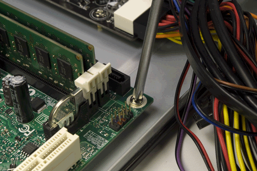
Figure 7-15. Secure the motherboard by driving screws into all four standoffs
Connecting motherboard cables
The final steps required to install the motherboard are to connect the various signal, data, and power cables. It doesn’t much matter in what order you connect these cables, but make sure to get all of them connected. Figure 7-16 shows the positions and pinouts of the connectors on the Intel D510MO motherboard. Refer to this diagram as you connect the cables.
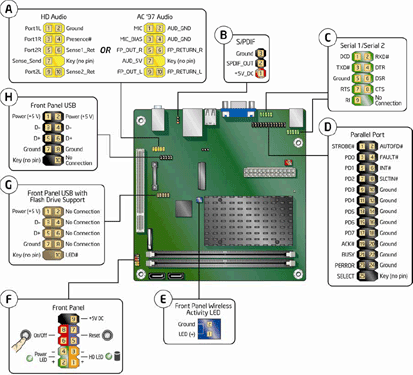
Figure 7-16. Locations of header-pin connectors on Intel D510MO motherboard (image courtesy of Intel Corporation)
To begin, locate the 2×12 main ATX power connector (item G on the diagram) on the motherboard and the corresponding power cable in the bundle of cables coming from the circuit board in the ISK300-65 case. The main ATX power cable in the ISK300-65 case is long enough to reach the socket on the D510MO motherboard, but only just. Get as much slack in that cable bundle as possible by separating unrelated cables from the main ATX power cable bundle.
Because it’s so short, you’ll have to route that cable bundle directly across the processor heatsink (the black multi-pronged assembly in the middle of the motherboard). Don’t be concerned about heat affecting the wires; the Intel Atom processor consumes very little power and produces very little heat. The tips of the heatsink prongs don’t become hot enough to melt the insulation on the wires.
Align the main ATX power cable connector as shown in Figure 7-17. Press it firmly into place until the latch on the cable connector snaps into place over the lip on the motherboard jack. Make absolutely sure that the latch snaps into place. A poorly seated ATX main power cable can cause many subtle and intermittent problems.
Next, locate one of the SATA data cables supplied with the motherboard (another good reason to buy a retail-boxed motherboard). Both ends of these cables have the same connectors, and either end can be used to connect to the motherboard or a drive. Note that each connector has a locking latch that mates with the connectors on the motherboard and drives. Make sure this latch snaps into the locked position when you connect a cable to either the motherboard or a drive. (Not all SATA cables have these latches; if you use a cable without a latch, simply make sure it’s fully seated in the socket.)
Use a permanent marker to draw a single line on each end of one cable, as shown in Figure 7-18. Although it may be obvious when you’re building the system which cable connects which motherboard SATA port to which drive, it will be less so with the cables bundled and dressed months later, when you want to upgrade or replace a drive. If your system uses more than two SATA ports, label the remaining cables as well: no lines for port 0, one line for port 1, two lines for port 2, and so on.
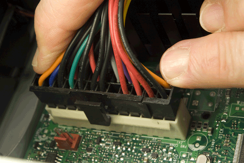
Figure 7-17. Align the main ATX power connector and press it firmly into place
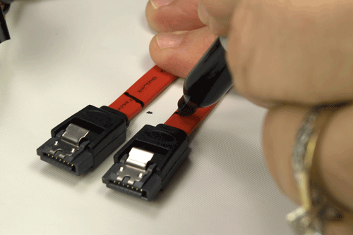
Figure 7-18. Label both ends of one SATA cable with one stripe for SATA port 1
Next, locate the Slimline SATA adapter in the Antec parts bundle. One end of this adapter has a single connector that fits both the SATA power and SATA data connectors on the slimline SATA optical drive. The other end of the adapter branches into a power cable with a Molex jack that connects to a Molex plug from the power supply board and a standard SATA data cable that connects to a motherboard SATA port. Connect the Slimline SATA adapter SATA data cable to motherboard SATA port 0 and one end of the standard SATA data cable to motherboard SATA port 1, as shown in Figure 7-19.
The next step is to connect the front-panel switch and indicator cables, as shown in Figure 7-20. Refer to section F on the diagram in Figure 7-16 for the pinouts. Each of the front-panel switch and indicator cables is labeled descriptively, e.g., “Power,” “Reset,” and “HDD LED.” Match those descriptions with the front-panel connector pins on the motherboard to make sure you connect the correct cables to the appropriate pins.
The power switch and reset switch connectors are unpolarized, so they may be connected in either orientation, as long as you connect each cable to the correct pair of pins. The HDD activity LED cable is polarized and should be connected with the correct polarity. (If you get it wrong, though, the worst that happens is that the LED fails to illuminate.)
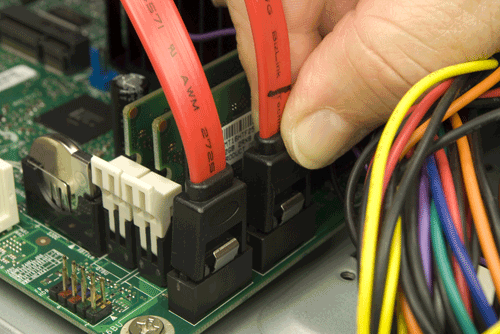
Figure 7-19. Connect one end of each SATA cable to the corresponding motherboard SATA port
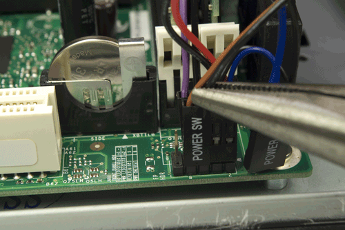
Figure 7-20. Connect the front-panel switch and indicator cables
The next step is to connect one of the front-panel audio cables to the audio header pins, which are located at the left rear of the motherboard, near the PCI expansion slot. The ISK300-65 case provides two monolithic front-panel audio cables—HD audio and AC’97—that are keyed with a blocked hole that corresponds with a missing pin on the motherboard connector. Align the HD audio cable connector as shown in Figure 7-21, and press firmly to seat it.
The final step in installing the motherboard is to connect the front-panel USB ports to the motherboard. The Antec ISK300-65 case provides a monolithic 10-pin (5×2) dual-port USB connector that matches the standard Intel USB pin assignments.
The Intel D510MO motherboard provides two internal USB 2.0 header-pin sets, but they are not identical. One set of USB header pins, labeled H in Figure 7-16, provides standard connections for two USB ports. That’s the one to which we’ll connect the front-panel USB cable. The second set of USB header pins actually provides only one standard USB port, plus an LED signal pin. That set of header pins is intended to be used to connect an internal SSD drive. We’ll leave that set of header pins unused, at least for now.
The Antec front-panel USB cable connector is keyed with one blocked hole that corresponds to the one missing pin in the Intel USB header-pin group. Orient the cable connector properly and slide it onto the header pins, as shown in Figure 7-22. If your case uses front-panel USB cables with individual connectors for each wire (or a different connector block pinout), refer to the pin assignment shown in Figure 7-16 to get those individual wires connected correctly.
Do what you can to bundle and tie off the cables and tuck them out of the way. Use the black plastic cable ties included in the ISK300-65 parts bundle.
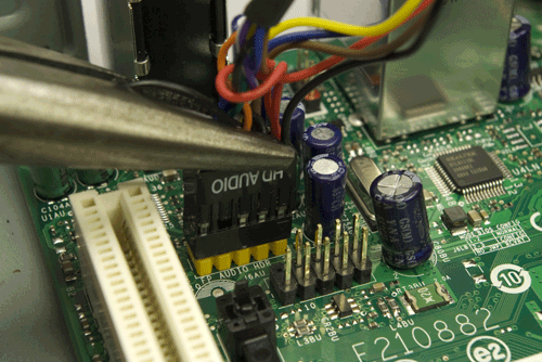
Figure 7-21. Connect the front-panel HD audio cable to the front-panel audio connector pins
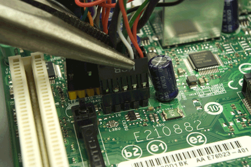
Figure 7-22. Connect the front-panel USB cable to the motherboard USB header pins
Installing the Drives
The Antec ISK300-65 has one external 5.25” drive bay for a slimline optical drive and two internal 2.5” drive bays for hard drives. Our motherboard provides only two SATA ports, which we’ll use to connect one optical drive and one hard drive.
The first step is to install the hard drive in the HDD tray. To do so, recover the drive tray assembly you set aside earlier. Remove the thumbscrew that secures the HDD tray to the drive tray assembly, as shown in Figure 7-23.
Slide the HDD tray back slightly to free the locking hinges, and lift the HDD tray away from the drive tray assembly, as shown in Figure 7-24.
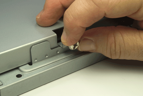
Figure 7-23. Remove the thumbscrew that secures the HDD tray to the drive tray assembly
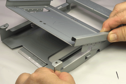
Figure 7-24. Lift the HDD tray free of the drive tray assembly
Slide the hard drive into the HDD tray, as shown in Figure 7-25, with one side of the drive under the retaining lip of the HDD tray. The rear (connector side) of the hard drive should be toward the rear of the tray, and overhanging slightly.
Hold the hard drive in position with your thumb, invert the tray, and place it on a flat surface. If necessary, move the drive until the drive screw holes align with the mounting holes in the HDD tray and insert the first screw. Drive that screw partially in, but leave enough slack that the drive can still move freely. Insert the remaining three screws and tighten all four screws finger-tight plus a quarter turn or so, as shown in Figure 7-26.
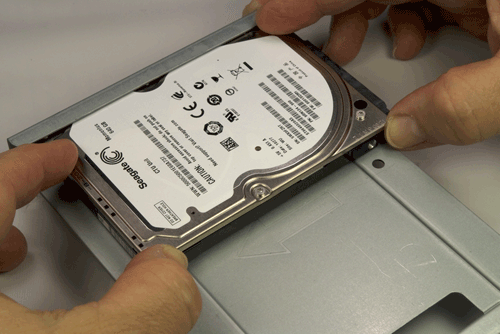
Figure 7-25. Orient the hard drive correctly, and slide it into the HDD tray
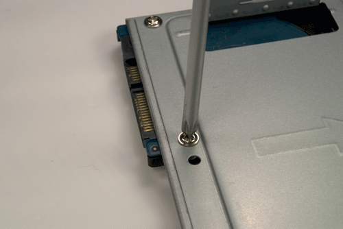
Figure 7-26. Holding the hard drive and tray inverted, partially drive one screw
At this point, following Antec’s instructions, we reattached the HDD tray to the drive tray assembly and reinserted the thumbscrew to secure the HDD tray to the drive tray assembly, as shown in Figure 7-27.
Although with the hard drive in place we were able to install the optical drive and connect the power and data cables to the hard drive and optical drive, in retrospect it would have been easier to replace the HDD tray in the drive tray assembly after we’d installed the optical drive and connected its data and power cables.
The next step is to install the optical drive. With the front of the case facing you, first strip the protective tape from the drive bezel.
Press gently on the upper-right corner of the optical drive bezel, as shown in Figure 7-28, and release the pressure to open the bezel, as shown in Figure 7-29.
Working from inside the case, use gentle finger pressure to pop the drive bay face plate free of the bezel, as shown in Figure 7-30.
Working from the rear of the assembly, slide the optical drive into position, as shown in Figure 7-31.
Locate the optical drive screw in the Antec parts bundle (it’s the tiniest screw there). Slide the optical drive back and forth until the screw hole in the optical drive is visible through the mounting hole just behind the HDD tray mounting thumbscrew in the drive assembly tray. Insert and tighten the optical drive screw to secure the optical drive, as shown in Figure 7-32.
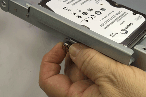
Figure 7-27. Reattach the HDD tray to the drive tray assembly
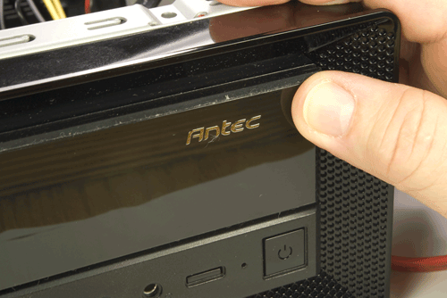
Figure 7-28. Press gently on the optical drive bezel to unlatch it
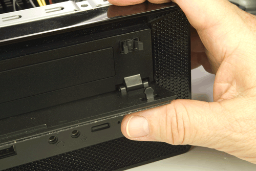
Figure 7-29. Release the optical drive bezel and allow it to pivot down
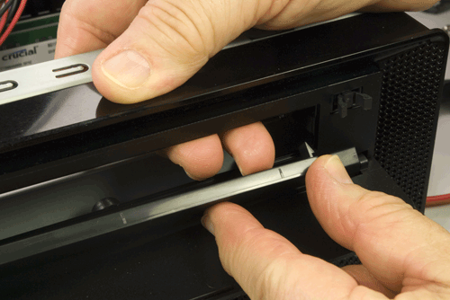
Figure 7-30. Press gently from inside the case to pop out the drive bay face plate
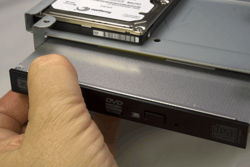
Figure 7-31. Slide the optical drive into the bay
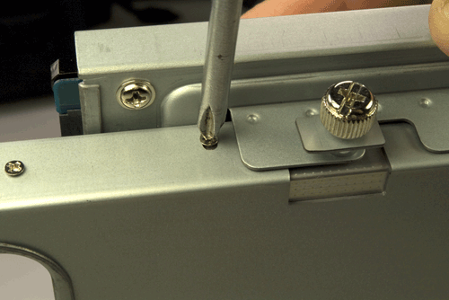
Figure 7-32. Insert the optical drive screw to secure the optical drive
Before you reinstall the drive tray assembly, you need to connect the case fan power cable and the Slimline SATA power cable. Locate the fan power cable and a Molex power cable from the power supply circuit board, and connect them, as shown in Figure 7-33.
After you connect the case fan power cable, set the fan speed switch on the top rear of the case. By default, it’s set to low. We recommend setting fan speed to high initially for better cooling. Only if you find the fan makes too much noise on high should you consider setting it to medium or low.
Locate another available Molex connector from the power supply, and connect the power jack from the Slimline SATA adapter to it.
The next step is to connect the Slimline SATA adapter to the optical drive, as shown in Figure 7-34. If necessary, you can remove the HDD tray temporarily and replace it after you connect the Slimline SATA adapter (as we did to shoot this image).
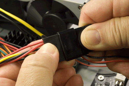
Figure 7-33. Connect the case fan power cable
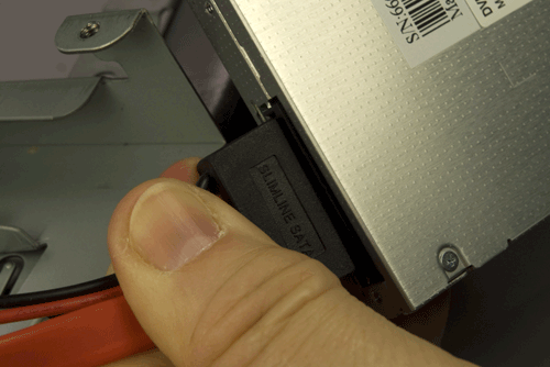
Figure 7-34. Connect the Slimline SATA adapter to the optical drive
We’re about to make things much less accessible, so before you proceed, do a final check of the interior of the case:
No loose tools or screws (shake the case gently)
I/O shield not fouled
Memory modules fully seated and latched
Main ATX power cable connected and latched
SATA data cables for hard drive and optical drive connected to motherboard
Front-panel switch and indicator cables connected properly
Front-panel audio and USB cables connected properly
Power connected to case fan and Slimline SATA adapter
Hard drive and optical drive secured to drive assembly tray
Slimline SATA adapter connected to optical drive
All cables dressed and tucked out of the way (insofar as possible)
Once you’ve completed the checklist, the next step is to reinstall the drive tray assembly. Slide it into position and secure it with three screws (one rear and two front), as shown in Figure 7-35.
Fish the SATA data and power cables for the hard drive up through the frame of the drive tray assembly and connect them to the hard drive, as shown in Figure 7-36.
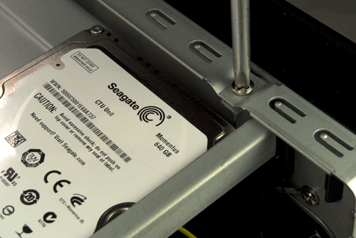
Figure 7-35. Reinstall the drive tray assembly and secure it with three screws
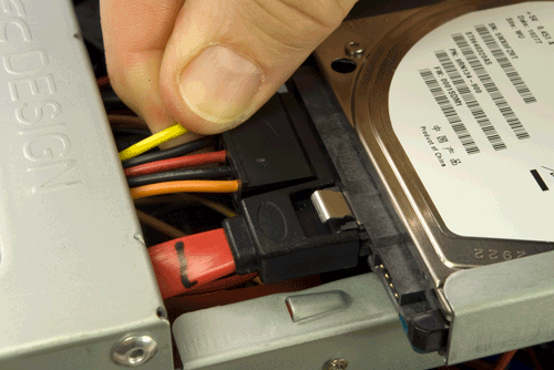
Figure 7-36. Connect the SATA data and power cables to the hard drive
Final Assembly Steps
Congratulations! You’re almost finished building the system. About all that remains is to reinstall the cover and fire up the system. Make one final check to verify that the cables are tucked away, the case fan is not fouled, and so on.
Once you’re satisfied that everything is correct, it’s time for the smoke test. Leave the cover off for now. Connect the AC power cable to the power brick, plug the AC cable into a wall receptacle, and then connect the DC cable from the power brick to the system unit. Press the main power button on the front of the case, and the system should start up. Check to make sure that the case fan is spinning. You should also hear the hard drive spin up. At that point, everything should be working properly.
Turn the system off and disconnect the DC power cable from the case. Before you reinstall the cover, locate the sticky labels in the motherboard box and apply them to the inside of the cover, making sure not to cover up any ventilation holes. Slide the cover back onto the case and reinsert the three thumbscrews at the rear of the case to secure the cover.
Move the system to the location where you plan to use it. Connect the keyboard, mouse, display, and Ethernet. Plug the AC cable from the power brick into a wall receptacle and the DC cable from the power brick into the jack on the rear of the case. Power up the display and turn on the system.
When the boot screen appears, enter BIOS Setup and verify that everything is as it should be (the full amount of memory recognized, time and date correct, and so on). Set the boot sequence to attempt booting from the optical drive first and the hard drive second. Save the BIOS settings and allow the system to reboot. Insert your Windows or Linux distribution disc in the optical drive, close the tray, and turn off the system. Restart the system, and follow the prompts to install Windows or Linux.
Final Words
Our appliance system failed the smoke test. (No, it didn’t erupt in a shower of sparks and gouts of smoke.) When we connected power to it, the green power LED on the motherboard lit, but nothing happened when we pressed the power button. Hmmm. So we went back and re-rechecked all the cable connections, and we found that the 24-pin main ATX power connector wasn’t completely seated. Pressing that down until the connector clicked into place solved the problem, and the system started normally.
We hit a home run with this system. It’s everything we hoped for, and more. Although the benchmarks say the dual-core Atom processor is only half the speed of the Athlon II X2 240 processor we used in the budget system and the server system, this system “feels” reasonably responsive running Windows 7 and even more so running Ubuntu 10.4 Linux. It’s obviously not suited to heavy multitasking—nor was it ever intended to be—but for web browsing, checking email, editing documents, and so on, it’s more than fast enough.
The system is very quiet if the case fan is running at low speed. At the default high speed, the case fan produces a whine that’s audible from across the room. Set to medium speed, the case fan is quiet enough to be inaudible from more than a couple of feet away. (It would be more noticeable in a quiet environment, but our den is about as noisy as most.) When Robert hooked up this system next to the sofa in the den and powered it up with the case fan set to low, he first thought the system wasn’t running. At low fan speed, which seems adequate to cool this system, you have to have your ear right next to the system to hear anything at all. The Seagate Momentus notebook drive is inaudible other than during heavy seeks, when a subdued clicking noise is barely audible.
We decided to push the limits of this system a bit, so we connected it temporarily to our HDTV and ran some video. SD (DVD) video rendered perfectly, so we decided to run a 1080p HD video clip from the hard drive to see how well the Atom processor and 5,400 RPM hard drive could keep up. Here we ran into the hardware limitations of this system. We’re not sure if the bottleneck was the Atom processor or the hard drive, but dropped frames and other artifacts were pretty obvious. Not that that mattered, because we didn’t design this system for media center use. The 2D video quality, running on Robert’s 22” LCD display, is excellent.
What would we change? Not a thing, except maybe the hard drive. The 5,400 RPM 640 GB Seagate Momentus 2.5” notebook hard drive provides high capacity and decent performance at a reasonable price, but a 5,400 RPM drive just isn’t as snappy as a 7,200 RPM drive. If we had been willing to trade off lower capacity against higher performance at the same price point, we’d have installed a 7,200 RPM 320 GB Seagate Momentus hard drive. But, on balance, we’re just as happy with the larger 5,400 RPM drive. Programs load a bit more slowly, it’s true, but then with 4 GB of memory we tend to keep our most-used programs loaded all the time anyway.