3. Building a Budget PC
Inexpensive doesn’t have to mean cheap. The myth persists that you can’t save money building your own PC, particularly a budget system. In fact, it’s easy to match the price of a mass-market commercial system with a home-built system that uses higher-quality components. Of course, you could instead match the quality level of a mass-market commercial system by buying the cheapest components available and save a few bucks by doing so, but we don’t recommend doing that. We think there are good reasons to build inexpensive systems, but no reasons at all to build cheap systems.
We define a budget system as one that seeks the maximum bang for the minimum buck, offering good component quality, reasonable performance, and high reliability. A budget PC uses good-quality components throughout, but those components fall on the low end of the performance range. They may even be a generation or two out of date. That’s not necessarily a bad thing, though: last year’s models are every bit as good this year as they were 12 months ago, and you can save a lot of money if you don’t insist on the very latest components.
In pursuit of low prices, we don’t hesitate to buy components that are discontinued and on sale. There are few disadvantages to doing so. Discontinued products nearly always carry the full manufacturer warranty and function as well as they did when they were the latest and greatest products available. Judicious shopping can easily knock $50 or more off the total cost of a budget system. That’s nothing to sneeze at when your total budget is only a few hundred dollars.
In this chapter, we’ll design and build the perfect budget PC.
Determining Functional Requirements
We began by sitting down to think through our own requirements for a budget PC. Here’s the list of functional requirements we came up with:
Reliability
Reliability is important for a budget PC, just as it is for any computer. Although our limited budget may force us to make minor compromises in reliability—such as using a lower-capacity power supply than we might otherwise choose—we’ll still keep reliability firmly in mind as we select components. When we’re forced to choose—as we inevitably will be—among performance, capacity, or features versus reliability, we’ll always favor the latter.
Adequate performance
In order to be useful, a budget PC must perform adequately. Cheap consumer-grade PCs are often obsolete the day they’re unpacked. Most of them have slow processors, insufficient memory, small hard drives, and very poor integrated video. That’s simply not good enough. For our budget PC, we’ll aim for a performance level that matches that of a mainstream or performance PC manufactured a year to 18 months earlier. That means we’ll need a processor in the 2.5+ GHz class (or a slightly slower dual-core model), at least 2 GB of memory, a 7,200 RPM hard drive of reasonable capacity, and either fast integrated video or an inexpensive standalone video adapter.
Usable peripherals
Cheap consumer-grade PCs always scrimp on peripherals. A typical cheap mass-market system is bundled with a $2 mouse, a $3 keyboard, a $3 set of speakers, a $20 DVD drive, and a $75 monitor, none of which are good for anything but the trash bin. We can do better than that, even within the constraints of our tight budget. We’ll have to spend an extra $5 here and $20 there, but we’ll end up with solid, usable peripherals that are likely to last for the life of the system.
Noise level
There’s little room in the budget for special quiet components, but that doesn’t mean a budget PC must necessarily be noisy. We’ll choose the quietest components available in our price range, always giving price and reliability high priority, but keeping noise level in mind as well. For example, two hard drives may be priced identically, but one may be literally twice as loud as the other. The same is true of other components, such as cases and power supplies. By choosing carefully, we can build a budget PC that is much quieter than a similar but noisier configuration that costs the same.
Hardware Design Criteria
With the functional requirements determined, the next step was to establish design criteria for the budget PC hardware. Here are the relative priorities we assigned for our budget PC. Your priorities may, of course, differ.
|
Price |
★★★★✩ |
|
Reliability |
★★★★✩ |
|
Size |
★✩✩✩✩ |
|
Noise level |
★★✩✩✩ |
|
Expandability |
★✩✩✩✩ |
|
Processor performance |
★★★✩✩ |
|
Video performance |
★★✩✩✩ |
|
Disk capacity/performance |
★★★✩✩ |
As you can see, this is a well-balanced system. Price and reliability are our top concerns, with everything else secondary. Here’s the breakdown:
Price
Price is the 900-pound gorilla for a budget system. We set our target cost for this system at $350 excluding external peripherals and software ($500 with the keyboard, mouse, speakers, and display), and we’ll try very hard to stay within that budget. That’s the same budget figure we used in the previous editions, but this time we’ll get a lot more computer for our money. With a $350 budget, we plan to spend roughly 50%—split about equally—on the motherboard, processor, and memory, 25% on the case and power supply, and 25% on the optical and hard drives.
Reliability
Reliability is as important as price. An unreliable system is not worth having. To get that reliability, we’ll use good brand-name components throughout.
Size
Size is unimportant, so we’ll pay it no mind. As it turns out, the best case for our purposes is a standard mid-tower unit.
Noise level
We’d like a quiet system, but we don’t have any extra money to spend to reduce noise. We’ll do what we can to choose the quietest possible inexpensive components, but otherwise we’ll let the chips fall where they may.
Expandability
Expandability is unimportant. If we do upgrade this system, say three years down the road, chances are we’ll be swapping components out rather than adding them.
Processor performance
Processor performance is moderately important for our budget PC, both initially and to ensure that the system will have enough horsepower to run new software versions without requiring a processor upgrade. We’d have loved to use a quad-core processor in this system, but there’s simply no room in the budget. We can only afford to spend perhaps $60 on the processor, which limits our choices to AMD or Intel single- or dual-core budget processors.
Video performance
2D video quality is important for our budget system, because it determines display clarity and sharpness for the browsers, office suites, and similar applications that this system will run. A budget system is not intended for serious gaming, so 3D video performance is relatively unimportant. Still, we’d like enough video horsepower for at least casual 3D gaming, so we’ll choose a motherboard with fast integrated video, such as the NVIDIA GeForce 8200. Just to keep our options open, we’ll make sure our motherboard provides a PCI Express x16 video slot. That way, if after a couple of years we need faster video, we can install a $50 PCI-E video adapter, which by then will be as fast or faster than the fastest video cards available today.
Disk capacity/performance
Disk capacity and performance are moderately important for the budget system. A small, slow hard drive can noticeably degrade system performance. Fortunately, fast hard drives of reasonably large capacity are relatively inexpensive. Rather than spending $30 on a small, slow hard drive, we’ll spend an extra $15 or $20 for a mainstream 7,200 RPM drive with midrange capacity.
Component Considerations
With our design criteria in mind, we set out to choose the best components for the budget PC system. The following sections describe the components we chose, and why we chose them.
Case and Power Supply
Antec NSK-4482 Mid-Tower Case (http://www.antec.com)
It’s easy to spend too little on the case and power supply for a budget system. When we searched NewEgg for computer cases with power supplies, we found more than 100 products for $50 or less. We wouldn’t use any of those on a bet. Cheap cases are bad enough: things don’t fit properly, and they’re full of burrs and sharp edges that make working on them dangerous. But cheap power supplies are worse. It’s simply not possible to build a reliable system using a cheap power supply. Even a budget system deserves a top-quality power supply, although a low-wattage unit—something in the 350W range—is sufficient.
Unfortunately, the price of a decent case and power supply has risen significantly over the last few years, probably because of the financial crisis and the decline of the U.S. dollar relative to Pacific Rim currencies. A couple of years ago, models suitable for a budget system sold in the $65 to $75 range. Equivalent cases now sell in the $90 to $100 range, which takes a larger bite out of our budget.
In that price range, we think the Antec NSK-4482 is the best choice. It’s very attractive, and the bundled EarthWatts 380 power supply is perfectly acceptable. Other suitable cases in that price range are the ThermalTake Element T and the Antec NSK-3480.
Shipping Coal to Newcastle
Incidentally, shipping cases is expensive. You can often save $20 or more if you can find a suitable case locally or a model online that includes free shipping.
Processor and CPU Cooler
AMD Athlon II X2 240 (http://www.amd.com)
We’d like a triple- or quad-core processor, but with only about $60 allocated to the processor, our choices are realistically limited to single- and dual-core “value” processors. Intel sells several models in this price range, but dollar-for-dollar in value processors, AMD models offer more bang for the buck than Intel models. At the time we purchased the processor for this system, the $60 retail-boxed AMD Athlon II X2 240 Regor dual-core processor was clearly the best processor for the money. Built on the 45 nm process, with two cores running at 2.8 GHz and maximum power consumption of 65W, this was the ideal processor for our budget system. Of course, by the time you order your $60 processor it’ll almost certainly be a faster model, but even this $60 value processor is no slouch in terms of performance.
We could actually have bought the 240 Regor processor for $53 rather than $60, but that would have been an OEM model rather than a retail-boxed model. That extra $7 bought us both a 3-year warranty (versus a 30-day warranty on the OEM model) and a reasonably quiet and effective CPU cooler. Given the choice, it’s almost always better to buy a retail-boxed processor than an OEM model.
Even though it’s a budget processor, the performance of the 240 Regor is reasonably good. Table 3-1 shows the overall performance of our budget processor compared to the processors used in the other project systems in this book, and, for reference, benchmarks for several processors in older but still useful systems we have around the house (RBT indicates systems used by Robert, and BFT indicates Barbara’s system). For comparison, we’ve also included the three primary desktop systems we were using when we wrote this book.
Figures Lie and Liars Figure
There’s really no way to assign a single number to quantify the overall performance of a processor. Two different processors with very similar benchmark scores may have noticeably different performance, depending on what you test. One may, for example, excel in rendering video but lag badly on another type of task, while the other is exactly opposite. We always take benchmark numbers with a (very large) grain of salt. That said, the Passmark CPU Mark score is a widely accepted metric for overall processor performance, so we include those one-number scores to give you an idea of how the budget processor holds up against the competition.
|
Table 3-1. Relative processor performance |
||
|
System |
Processor |
CPU Mark score |
|
Extreme system |
Intel Core i7 X 980 |
10,140 |
|
Current office desktop system (RBT) |
Intel Core2 Quad Q9650 |
4,583 |
|
Mainstream system |
Intel Core i5 661 |
3,170 |
|
Media center system |
Intel Core i3 530 |
2,714 |
|
Current den system (RBT) |
Intel Core2 Duo E6750 |
1,663 |
|
Budget and home server systems |
AMD Athlon II X2 240 |
1,640 |
|
Current office desktop system (BFT) |
Intel Core2 Duo E6400 |
1,263 |
|
Appliance/nettop system |
Intel Atom D510 |
666 |
|
(Older system) |
Intel Pentium 4 3.80 GHz |
638 |
|
(Older system) |
AMD Athlon 64 4000+ |
628 |
|
(Older system) |
Intel Celeron 540 |
493 |
|
(Older system) |
Intel Pentium 4 3.00 GHz |
488 |
|
(Older system) |
AMD Sempron 3100+ |
449 |
Although the Core i7 processor we’re using in the extreme system is more than six times faster than our budget processor, the performance of the budget processor holds up very well in comparison to that of two of our current primary systems, both of which were high-performance systems when they were built. (We were stunned to see just how well that Core2 Quad held up; we built that system almost two years earlier as an Extreme System and, with a CPU Mark score considerably higher than some current Core i7 processors, the Core2 Quad still nearly qualifies for that designation.)
The Core i3, which qualifies as a low-mainstream processor, is nearly twice as fast as our budget processor, but it also costs twice as much. And the 240 Regor budget processor is more than twice as fast as the Intel Atom D510, which itself is faster than processors like the Intel Pentium 4 and Celeron and the AMD Athlon 64 and Sempron, all of which are still in use in tens of millions of systems.
If you can afford to spend a bit more for the processor, consider something like the triple-core AMD Athlon II X3 435 Rana. An extra $15 or so buys you a 50% performance boost in processor performance over the 240 Regor, taking you into the low-mainstream processor class. (Of course, other than for processor-bound tasks, 50% faster processor performance doesn’t translate into 50% faster system performance, but it does provide noticeably snappier response times.)
Motherboard
ASRock K10N78M-PRO (http://www.asrock.com)
The 240 Regor is a Socket AM3 processor, so the first selection criterion for a motherboard in the $60 range was Socket AM3 compatibility, which either a hybrid Socket AM2+/AM3 model or a pure Socket AM3 model provides. (A hybrid motherboard can use either a Socket AM2+ or a Socket AM3 processor; an AM3 motherboard can use only a Socket AM3 processor.) Note that socket compatibility is only a first-cut criterion. Just because a motherboard supports Socket AM3 processors doesn’t necessarily mean it supports the specific Socket AM3 processor you want to use.
We’d prefer to use a first-tier motherboard from GIGABYTE or ASUS, both of which offer Socket AM3 motherboards in this price range. Unfortunately, budget motherboards from first-tier makers are feature-light. For example, they may offer only 100BaseT (100 megabit/second) networking rather than 1000BaseT (1,000 Mb/s, or gigabit), and their integrated video is several generations out of date. So we narrowed things down by looking for a suitable motherboard made by ASRock, a second-tier motherboard manufacturer that is famed for its first-tier quality. We found several ASRock candidates in the $55 to $65 range.
Narrowing things further, we wanted integrated video in the NVIDIA GeForce 8200 or ATI RADEON HD 3200 class, either of which provides excellent 2D display quality and has enough 3D horsepower to use for casual gaming. (Boards with integrated RADEON HD 4200 sell for a few dollars more, and you might expect they’d outperform the GeForce 8200/RADEON 3200 boards, but they don’t. The next real step up from the 8200/3200 boards are ones with integrated RADEON HD 3300, and those were selling for $85 or so when we bought our motherboard.) We also want a PCI Express x16 slot in case we want to upgrade the graphics at some point.
We would prefer DDR3 memory for its faster transfers, but in practical terms overall system performance will be very similar with DDR2 memory. At the time we ordered components for this system, DDR2 and DDR3 memory modules of the same capacity were selling for about the same price, but DDR3 motherboards were still selling for a $15 or more premium over comparable DDR2 motherboards, so we decided that a DDR2 motherboard was the better choice.
Among the motherboards that met our requirements and sold for about $60, the best choice was the ASRock K10N78M-Pro. Although it lacks bells and whistles, it has exactly the feature set we wanted: NVIDIA GeForce 8200 integrated video with support for DX10 (gaming graphics), a PCI Express x16 slot for future video upgrades, four SATA 3.0 Gb/s ports (with software RAID 0/1/5/10 support), good 5.1 audio, an integrated 1000BaseT network adapter, six USB 2.0 ports, and so on. At about $60, the ASRock K10N78M-Pro was a perfect fit for our budget system.
The final step, which you ignore at your peril, is to verify that the selected motherboard is compatible with your processor. We visited the ASRock K10N78M-Pro web page and located the processor compatibility list. We had a bad moment when we didn’t find our 240 Regor retail-boxed processor (model ADX240OCGQBOX) in the motherboard compatibility list, so we visited the AMD web page for the ADX240OCGQBOX and found that the OEM version of that product had a significantly different product code, ADX240OCK23GQ. That product code did appear in the compatibility list. Since the OEM and retail-boxed versions of that processor are actually identical, we knew the retail-boxed 240 Regor would be compatible with our K10N78M-Pro motherboard. Furthermore, the compatibility list said the 240 Regor was compatible with all BIOS versions, so we knew we wouldn’t get stuck with an earlier BIOS that wouldn’t boot with our processor.
Memory
Crucial CT2KIT12864AA667 2 GB Kit (1 GB x 2) (http://www.crucial.com)
The budget system in the preceding edition was equipped with a single-core processor and 512 MB of RAM. Although that was sufficient for snappy performance with Linux or Windows XP, it was marginal for Vista. Windows 7 resource requirements are at least as high as those of Vista, so if you plan to run Windows 7 on your budget system, you’ll want at least 1 GB per core, for a total of 2 GB. That’s assuming you’re running 32-bit Windows 7. If you plan to run the 64-bit version, double the memory requirements.
When we ordered the parts for this system, we found that our $60 budget for memory was sufficient to buy 2 GB, either as two 1 GB DIMMs or as one 2 GB DIMM. We’d have preferred to install 4 GB, but, at $95 or so, a pair of 2 GB DIMMs would have busted our budget. We plan to run Linux, which will be happy with 2 GB, but if we planned to run Windows 7 we’d try very hard to come up with an extra $40 or so to expand the memory to 4 GB.
Which brings up another issue. The ASRock K10N78M-Pro motherboard supports dual-channel memory operation but has only two DIMM slots. For best memory performance, both of those slots need to be occupied, but of course that leaves no free slots for future upgrades. If we were installing 4 GB of memory there wouldn’t be any real decision, as one 4 GB DIMM costs more than twice as much as two 2 GB DIMMs. But installing only 2 GB of memory gives us the option of installing just one 2 GB DIMM (about $50 when we were ordering parts) and thereby sacrificing some memory performance, or installing two 1 GB DIMMs (about $25 each) and thereby giving up a free memory slot for future expansion. You pays your money and you takes your choice.
Family Matters
We actually ended up installing 4 GB of memory in this system. Just as we were about to build the system, Barbara’s sister, Frances, called to say her desktop PC was having problems. We originally thought it would require only a power supply replacement, but when we popped the lid we realized that the system was four years old. That’s getting perilously close to the design life of a PC, so we decided to turn our budget system into a new system for Frances. Chances are she’ll use the new system for another four years, so we decided it made sense to install 4 GB of memory and be done with it.
Video Adapter
Integrated NVIDIA GeForce 8200
The NVIDIA GeForce 8200 video integrated on the ASRock motherboard provides excellent 2D display quality and reasonably good 3D performance for casual gaming and similar tasks. The ASRock motherboard includes a PCI Express x16 video adapter slot, so if necessary we can upgrade the video down the road by installing an inexpensive PCIe video adapter. We don’t expect that to be necessary, but if we decide we need more video horsepower than the GeForce 8200 provides, even a $30 standalone video adapter is likely to be more than sufficient.
Hard Disk Drive
Seagate Barracuda 7200.12 ST3500418AS 500GB
(http://www.seagate.com)
If we were attempting to cut costs to the bone, we might have chosen a low-capacity hard drive. But when we bought our components, 80 GB drives were selling for $30, versus $45 for the 500 GB Seagate. We decided it made sense to spend the extra $15 to jump from 80 GB to 500 GB. That additional cost is significant for a system with a base budget of $350, but the extra $15 buys us more than six times as much disk space. Even on a budget system, we’d soon be cramped with only 80 GB of disk space.
We’ve been using Seagate hard drives almost exclusively for many years and have always found them to be fast, quiet, cool-running, reliable, and competitively priced. (Our contacts at data recovery firms also run Seagate drives in their personal systems, which we think speaks volumes.) If for some reason you prefer another brand, Samsung and Western Digital would be our second choices.
Optical Drive
ASUS DRW-24B1ST DVD writer (http://www.asus.com)
DVD burners are so inexpensive nowadays that it makes little sense to save $5 by installing a read-only DVD-ROM drive. If nothing else, you’ll want the writer to back up your system. Among the many inexpensive DVD writers available, we chose the ASUS DRW-24B1ST for its combination of features, performance, reliability, and price. Similar models from LiteOn or Samsung are also good choices.
Keyboard and Mouse
Logitech Deluxe 250 Desktop (http://www.logitech.com)
Personal preference outweighs all else when choosing a keyboard and mouse. So many personal factors determine usability that no one can choose the “best” keyboard and mouse for someone else.
That said, we had to pick a “budget” keyboard and mouse for our budget system. We wanted something in the sub-$20 range that included a decent keyboard and a reliable optical mouse. Our favorite among inexpensive keyboard/mouse combos is the Logitech Deluxe 250 Desktop, for which we paid $17. If you prefer Microsoft keyboards and mice, the Microsoft Basic White Value Pack 2.0 or the Microsoft Wired Desktop 400 is also a good sub-$20 choice.
Speakers
Logitech LS11 (http://www.logitech.com)
Even a budget system needs a decent set of speakers, but we can realistically spend no more than $15 on speakers. In that price range, we recommend the Logitech LS 11 2.0 speaker set. Note, however, that many LCD displays include built-in speakers, which adds little or nothing to their price and can eliminate some desktop clutter. Display speakers are generally small and produce only 0.5W to 1W per channel. That’s acceptable for most uses, including watching videos and so on. The $15 standalone units provide somewhat better sound but about the same wattage. We opted for speakers embedded in the display for our budget system.
Rachel Head Comments
Neatly recouping the extra $15 spent on the hard drive!
Display
19”:
ASUS VW193TR (http://www.asus.com)
ASUS VH196T
ASUS VH198T
Hanns.G HW191APB (http://www.hannsg.com)
20”:
ASUS VH202T-P
Hanns.G HZ201HPB
Samsung P2050 (http://www.samsung.com)
ViewSonic VX2033wm (http://www.viewsonic.com)
In the preceding edition, we allocated $120 to the display and recommended three 17” CRT models from NEC, Samsung, and ViewSonic. Nowadays, $120 buys you a lot more display. The entry level for LCD displays is now a 19” 1440×900 model. (There are smaller displays available, but they generally cost the same as a 19” model, if not more.) Basic models suitable for a budget system cost $110 to $130. In the $130 to $160 range, you can buy a 20” model with 1600×900 resolution, a nice step up. You’re likely to be happy with any of the models listed above, or their successors. Note that some models include speakers and others do not.
Matching Displays to Video Adapters
In the past, gamers tended to choose only those LCD displays that had the fastest response times, because many mainstream displays had response times too slow to provide high-quality gaming video. That’s less of an issue nowadays, because all but the least expensive LCD displays are fast enough to provide at least reasonable gaming response.
Serious gamers also choose displays with native resolutions that match the optimum video adapter settings for their systems. For example, a gaming rig may be able to display 3D games at 2560x1600 resolution, but only at unacceptably slow frame rates. Rather than use such a high-resolution display, a gamer might use a 1600x1050 display, at which resolution the frame rates are acceptably fast.
The ASRock K10N78M-PRO motherboard’s integrated NVIDIA GeForce 8200 video supports resolutions up to 1920x1200 on the DVI video output and is more than fast enough to provide excellent 2D video quality at its highest resolution. But if you plan to do any 3D gaming with your budget system, be aware that for many 3D games the GeForce 8200 will not be fast enough to drive a high-resolution display at anything near full resolution with usable frame rates.
If you don’t want to install a faster video adapter—and perhaps a faster processor as well—the alternatives are to use less demanding game settings, accept lower frame rates, or run at lower than nominal resolution, which may cause blockiness and other video artifacts. With resource-intensive 3D games, you may have to make all three of these compromises, and even then performance may be unacceptable. Still, a budget system isn’t designed for serious 3D gaming, and this system as configured can play many less demanding 3D games with acceptable performance.
Component Summary
Table 3-2 summarizes our component choices for the budget system. Not counting shipping, sales tax, or software, the total for the budget system came to $351. With display, the budget system cost $475, give or take. Not bad for a fully equipped system. We could have made small economies here and there to reduce the price further. For example, we might have saved $25 by buying a really cheap case (although we’d still have installed a $40 Antec EarthWatts 380 power supply, or something similar). We could have saved $10 on the motherboard by accepting less capable integrated video and another $20 by using a slow single-core processor. Substituting a smaller hard drive might have saved us another $15, and we could have cut maybe $5 from the total by using a DVD-ROM drive rather than a DVD writer. All told, we might have gotten the cost of our budget system down into the $300 range, but we feel that would have been a false economy.
|
Table 3-2. Bill of materials for budget |
|
|
Component |
Product |
|
Case |
Antec NSK-4482 Mid-Tower Case |
|
Power supply |
Antec EarthWatts 380W (bundled) |
|
Motherboard |
ASRock K10N78M-PRO |
|
Processor |
AMD Athlon II X2 240 |
|
CPU cooler |
(Bundled) |
|
Memory |
Crucial CT2KIT12864AA667 2 GB Kit (1 GB x 2) |
|
Video adapter |
(Integrated NVIDIA GeForce 8200) |
|
Hard disk drive |
Seagate Barracuda 7200.12 ST3500418AS (500GB) |
|
Optical drive |
ASUS DRW-24B1ST DVD writer |
|
Keyboard and mouse |
Logitech Deluxe 250 Desktop |
|
Speakers |
Logitech LS11 (or embedded display speakers) |
|
Display |
(See text) |
Reality Check
When Barbara’s sister Frances’s system—the budget system from the preceding edition of this book—failed after more than four years of heavy use, it caught us at a bad time. We could have fixed her system, but at four years old it was nearing the end of its design life anyway. We didn’t have any suitable spare systems sitting around, and we weren’t quite ready to build this budget system. Frances needed a system quickly, so she asked us to look at the systems Costco had on offer and pick one out for her.
The least expensive desktop system on the Costco website was a Dell Inspiron 570, for $499.99 plus tax and shipping. For $150 more, the Inspiron 570’s general specifications matched those of our budget configuration almost exactly, except that it had 4 GB of RAM rather than 2 GB and included a Windows 7 license. Making those two changes would have increased our total cost by about $130, just $20 short of the Dell price. So why bother?
Because the two systems are only superficially similar. Granted, both have exactly the same processor and the same or similar hard drives, but otherwise the Dell system has lower-quality components. Our system has a better case and power supply, a higher-quality motherboard, top-notch memory, a faster optical drive, and a better keyboard, mouse, and speakers.
Also, paying $90 or so for a Windows 7 license would be a waste. Frances has been using Linux for years and has no desire to use (or pay for) Windows. So, our system costs about $110 less and is built with higher-quality components. That’s a no-brainer.
Building the Budget System
Figure 3-1 shows the major components of our budget system. The Antec NSK-4482B case is at the upper left, with the ASRock K10N78M Pro motherboard to its right. In the foreground, left to right, are the Crucial 4 GB memory kit, the ASUS DRW-24B1ST DVD writer, the 500 GB Seagate Barracuda hard drive, and the AMD Athlon II X2 240 Regor processor.
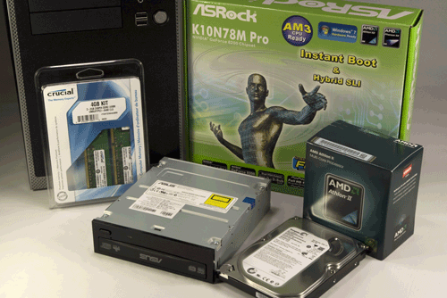
Figure 3-1. Budget system components, awaiting construction
Before you proceed, make sure you have everything you need. Open each box and verify the contents against the packing list. Once you’re sure everything is present and accounted for, it’s time to get started.
It’s As Easy As 2, 1, 3
Although by necessity we describe building the system in a particular order, you don’t need to follow that exact sequence when you build your own system. Some steps—for example, installing the processor and memory before installing the motherboard in the case—should be taken in the sequence we describe, because doing otherwise makes the task more difficult or risks damaging a component. But the exact sequence doesn’t matter for most steps. As you build your system, it will be obvious when sequence matters.
Preparing the Case and Installing Drives
The first step in building any system is always to make sure that the power supply is set to the correct input voltage. Some power supplies, including the Antec EarthWatts 380, set themselves automatically. Others must be set manually using a slide switch to select the proper input voltage. Bundled power supplies are nearly always set properly by default, if applicable, but there are rare exceptions, so it’s always a good idea to verify the input voltage setting before you proceed.
![]() Avoid Fireworks
Avoid Fireworks
If you connect a power supply set for 230V to a 115V receptacle, no harm is done. The PC components will receive only half the voltage they require, and the system won’t boot. But if you connect a power supply set for 115V to a 230V receptacle, the PC components will receive twice the voltage they’re designed to use. If you plug in the system, that overvoltage will destroy it instantly in clouds of smoke and showers of sparks.
To begin preparing the case, remove the two thumbscrews that secure the top panel, as shown in Figure 3-2.
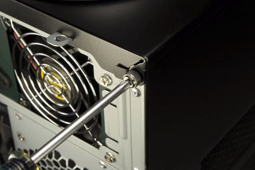
Figure 3-2. Remove the two thumbscrews that secure the top panel
After you remove both thumbscrews, slide the top panel slightly toward the rear, as shown in Figure 3-3, and then lift it off.
With the top panel removed, lift the left side panel straight up and remove it, as shown in Figure 3-4. Remove the right side panel in the same manner. Put the top panel and both side panels safely aside, where they won’t be scratched while you are building the system.
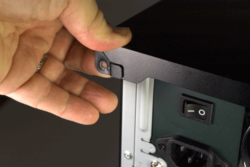
Figure 3-3. Slide the top panel to the rear to release it
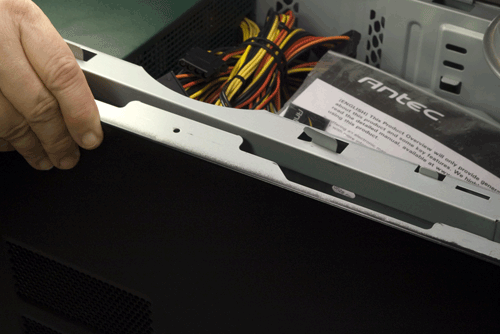
Figure 3-4. Remove the side panels and set them safely aside
The next step is to remove the internal 3.5” drive bay, which is secured by three screws. One screw, shown in Figure 3-5, secures the internal 3.5” drive bay to the 5.25” drive bay above it. Two other screws, one visible in Figure 3-6, secure the bottom front of the internal 3.5” drive bay to the inside front of the chassis. Remove all three of those screws. (You may find it easier to remove the two lower screws if you turn the case on its side temporarily.)
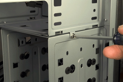
Figure 3-5. Remove the screw that secures the side of the 3.5” internal drive bay to the 5.25” drive bay above it
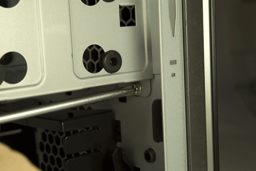
Figure 3-6. Remove the two screws that secure the bottom of the 3.5” internal drive bay to the front of the chassis
After you remove all three screws, slide the drive bay slightly toward the rear of the chassis to free the locking tabs and lift the drive bay clear of the chassis, as shown in Figure 3-7.
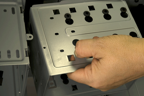
Figure 3-7. Slide the 3.5” internal drive bay slightly toward the rear of the case and lift it out
![]() Fragile Connectors
Fragile Connectors
Be extremely careful when you remove and replace the internal 3.5” drive bay. When this bay is removed, the panel ends of the front-panel connector wires are visible, including those for the power switch. The fine-gauge wires connect to tiny pins on the backs of the switches, and somehow we managed to pull the power switch wire loose from the power switch.
We didn’t discover that until we were connecting the power switch wires to the motherboard, so we had to remove the internal 3.5” drive bay to repair the connection. The pins on the power and reset switches are tiny and fragile, so it would be quite possible to snap them off entirely by putting tension on the wires connected to them. You have been warned.
Place the drive bay on a flat surface, right-side up. Slide your hard drive into the drive bay, with the rear (data and power connector side) of the hard drive toward the rear of the drive bay. Slide the drive forward and backward until two of the screw holes in the hard drive align with the holes in the rubber grommets on the drive bay. When the drive is correctly aligned, the rear of the drive should protrude slightly from the rear of the drive bay, as shown in Figure 3-8.
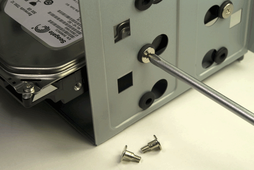
Figure 3-8. Slide the hard drive into the internal drive bay and secure it with four hard drive mounting screws
The parts bag includes special screws designed to mount hard drives in this bay. These screws (two of them fully visible in Figure 3-8) are threaded for only part of their length. The unthreaded portion is supported by the silicone grommet, which isolates the drives to reduce noise and vibration. Insert four of these screws, two per side, and tighten them finger-tight plus a quarter turn or so. Do not overtighten the screws, or you’ll eliminate the benefits of the grommets.
If you have more than one hard drive to install, repeat these steps for the other drives. If you’re installing two drives, leave at least one unoccupied mounting slot between them to improve ventilation.
After you install the hard drive or drives in the bay, slide the drive bay back into position, as shown in Figure 3-9. Make sure the locking tabs and slots on the two drive bays latch into position as you slide the bay into place. Also note the slot on the center-front edge of the drive bay (visible at the bottom of Figure 3-9), which mates with a corresponding metal tab on the chassis.
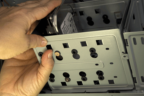
Figure 3-9. Slide the internal drive bay back into place and secure it with the three screws you removed earlier
Once the drive bay is correctly positioned, maintain slight pressure on it toward the front of the case to force the side screw holes into alignment. Reinsert and tighten the screw that secures the internal 3.5” drive bay to the 5.25” drive bay above it. Then reinstall the two screws that secure the bottom of the internal 3.5” drive bay to the chassis.
The next step is to install the optical drive. To begin, use your fingers from inside the case to press outward on the top plastic bezel cover until it snaps free, as shown in Figure 3-10.
If you have a second 5.25” device to install (such as the Antec Easy SATA hard drive docking station), you’ll need to prepare a second 5.25” drive bay. To do so, use a screwdriver to twist the metal RF shield (behind the plastic bezel cover) back and forth until it snaps free.
![]() Sharp Edges
Sharp Edges
Be careful when removing the metal RF shield, and be careful working in that drive bay later. Snapping the metal RF shield free leaves a sharp burr on the top edge of the remaining RF shield.
Using both thumbs, slide the optical drive into the drive bay, as shown in Figure 3-11. If it binds, pull the drive out slightly and reseat it. Press the drive bezel flush with the case bezel.
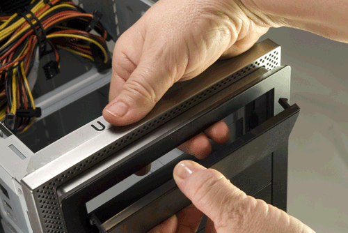
Figure 3-10. Working from inside the case, press the top plastic drive bay bezel until it snaps out
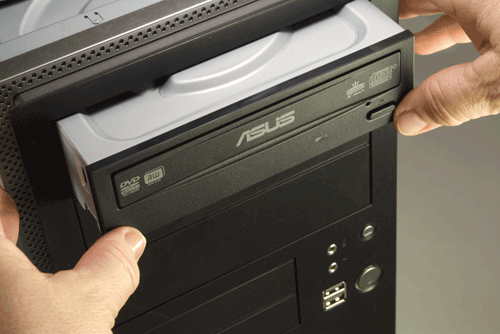
Figure 3-11. Slide the optical drive into the drive bay until its bezel is flush with the case bezel
Locate the optical drive mounting screws in the parts bag. These screws are the most finely threaded in the bag. Use at least four screws (two per side) to secure the optical drive to the chassis, as shown in Figure 3-12. Tighten the screws finger-tight plus maybe a quarter turn. (It’s difficult to overtorque these screws because their heads are quite shallow. Your screwdriver will lose its grip before you can overtighten them.)
Note the shorter screw slot at the top-front position in Figure 3-12. Using a screw in that position prevents the drive from sliding back into the case more than a tiny fraction of an inch. We actually used six screws—one at the rear on each side and two at the front on each side—but if you use only one front screw per side, install it in that shorter slot position.
Nearly every case we’ve ever used, including the Antec NSK-4482, comes with a generic I/O shield. The generic shield never matches the motherboard I/O panel, so you’ll need to remove the stock I/O shield and replace it with the one supplied with the motherboard.
To remove the I/O shield, use a tool handle to press from outside the case until the I/O shield pops loose, as shown in Figure 3-13. Be careful with your fingers: I/O shields are made of thin metal and may have edges sharp enough to cut you. Don’t worry about damaging the generic I/O shield supplied with the case. You can discard or recycle it.
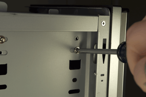
Figure 3-12. Use at least four screws (two per side) to secure the optical drive to the chassis
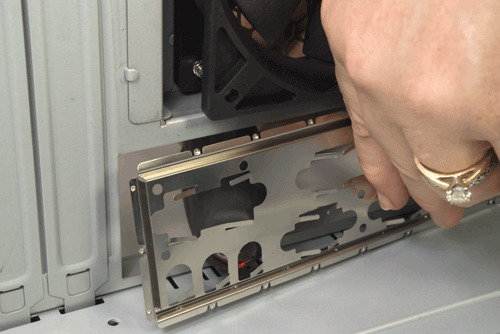
Figure 3-13. Remove the I/O shield supplied with the case
Like all motherboards, the ASRock K10N78M-PRO comes with a custom I/O shield that matches the motherboard I/O panel. Before you install the custom I/O shield, compare it to the motherboard I/O panel to make sure the holes in the I/O shield correspond to the connectors on the motherboard.
Once you’ve done that, press the custom I/O shield into place. Working from inside the case, align the bottom, right, and left edges of the I/O shield with the matching case cutout. When the I/O shield is positioned properly, press gently along the edges to seat it in the cutout, as shown in Figure 3-14. It should snap into place, although getting it to seat properly sometimes requires several attempts. It’s often helpful to press gently against the edge of the template with the handle of a screwdriver or nut driver.
![]() Avoid Brute Force
Avoid Brute Force
Be careful not to bend the I/O shield while seating it. The template holes need to line up with the external port connectors on the motherboard I/O panel. If the template is even slightly bent, it may be difficult to seat the motherboard properly.
After you install the I/O shield, carefully slide the motherboard into place, making sure that the back panel connectors on the motherboard are firmly in contact with the corresponding holes on the I/O shield. Compare the positions of the motherboard mounting holes with the standoff mounting positions in the case. One easy method is to place the motherboard in position and insert a felt-tip pen through each motherboard mounting hole to mark the corresponding standoff position beneath it. Alternatively, you can simply look down through the motherboard mounting holes to determine which chassis positions need to have standoffs installed and then mark those positions with a felt-tip pen, as shown in Figure 3-15.
Seeing the Light
If you simply look at the motherboard, it’s easy to miss one of the mounting holes in all the clutter. We generally hold the motherboard up to a light, which makes the mounting holes stand out distinctly.
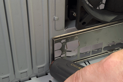
Figure 3-14. Install the I/O shield supplied with the motherboard
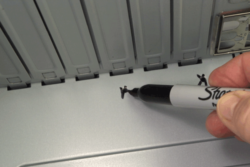
Figure 3-15. Locate and mark the proper positions for standoffs to be installed
The ASRock K10N78M-PRO motherboard has six mounting holes. Some cases are shipped with several standoffs already installed, but the Antec NSK-4482 has no standoffs preinstalled. So, we need to install standoffs in all six of the positions required by the motherboard.
![]() Avoid Grounding Problems
Avoid Grounding Problems
If your case comes with preinstalled brass standoffs, make absolutely certain that each standoff matches a motherboard mounting hole. If you find one that doesn’t, remove it. Leaving an “extra” standoff in place may cause a short circuit that may damage the motherboard and/or other components, or at least cause a boot failure.
Also, if you use a case that uses stamped raised areas in the motherboard tray instead of standoffs, be aware that some motherboards may fail to boot in such cases because the raised areas ground parts of the motherboard that were not intended to be grounded.
Install brass standoffs for each motherboard mounting hole. Although you can screw in the standoffs using your fingers or needlenose pliers, it’s much easier and faster to use a 5 mm nut driver, as shown in Figure 3-16. Tighten the standoffs finger-tight, but do not overtighten them. It’s easy to strip the threads by applying too much torque with a nut driver.
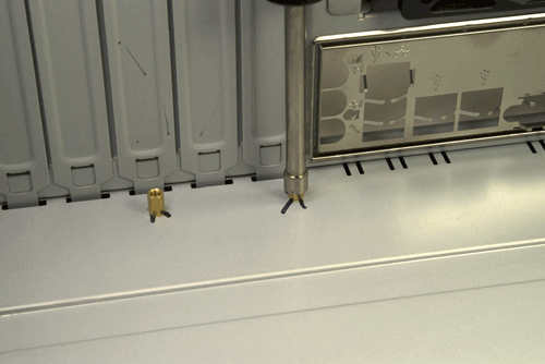
Figure 3-16. Install a brass standoff at each marked position
Once you’ve installed all the standoffs, do a final check to verify that (a) each motherboard mounting hole has a corresponding standoff, and (b) no standoffs are installed that don’t correspond to a motherboard mounting hole. As a final check, we usually hold the motherboard in position above the case and look down through each motherboard mounting hole to make sure there’s a standoff installed below it.
Pen and Paper
Another method we’ve used to verify that all standoffs are properly installed is to place the motherboard flat on a large piece of paper and use a felt-tip pen to mark all the motherboard mounting holes on the paper. We then line up one of the marks with the corresponding standoff and press down until the standoff punctures the paper. We do the same with a second standoff to align the paper, and then press the paper flat around each standoff. If we’ve installed the standoffs properly, every mark will be punctured, and there will be no punctures where there are no marks.
Populating the Motherboard
With the case prepared, the next step is to populate the motherboard by installing the processor, CPU cooler, and memory. To begin, place the motherboard on a firm, flat surface. Place the pink antistatic foam supplied with the motherboard between it and the work surface to protect the motherboard against physical or static electricity damage.
Locate the metal cam lever on the side of the processor socket. In its closed position, along the edge of the processor socket, this lever applies pressure to lock the processor pins into the socket. In its open position, with the lever vertical relative to the socket, that pressure is released, allowing a processor to be inserted or removed without damaging the pins. Press the cam lever slightly outward (away from the socket) to release it from the plastic latches that secure it, and then lift the lever, as shown in Figure 3-17, to the full vertical position.
Open the processor box and remove the hard plastic shell that contains the processor. Touch the chassis or power supply to ground yourself before you open that plastic shell and touch the processor itself. Be careful when opening the inner packaging. More than once, we’ve had the plastic shell give way suddenly and ended up with the processor dropping into our laps (or flying across the room…).
Open the inner package carefully and remove the processor from the antistatic foam bed upon which it rests. Orient and align the processor with the processor socket. The socket has an arrow on one corner that corresponds to an arrow on one corner of the processor. Make sure these arrows are aligned, and then simply drop the processor into the socket, as shown in Figure 3-18.
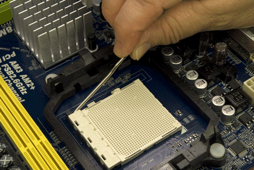
Figure 3-17. Release the cam lever from the processor socket and lift it up
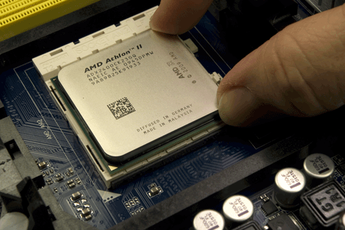
Figure 3-18. Orient and align the processor properly with the socket and then drop it into place
The processor should seat flush with the socket without any pressure being applied. Never press down on the processor, or you may bend the processor pins and ruin it. If the processor doesn’t drop into the socket freely, it’s not aligned properly. Realign it and try again until it drops easily into the socket and seats completely.
Once the processor is seated properly, press the metal cam lever downward toward the socket and snap it into position under the plastic locking tab on the socket, as shown in Figure 3-19. You should feel some resistance on the lever as the cam clamps the processor pins into the socket. If you feel any more than very slight resistance, release the pressure, verify that the processor is correctly seated, and try again.
After you install the processor, the next step is to install the CPU cooler. Before you install the cooler, examine the bottom of the heatsink to verify that the patch of thermal compound is present and undamaged.
A Penny Saved Is a Hundred Dollars Wasted
If you ever remove and replace the processor, don’t attempt to reuse the thermal compound. Rub off any compound present on the processor surface and the heatsink base—if it’s tenacious you can warm it slightly with a hair dryer—and then polish both the processor surface and the heatsink base with a clean paper towel to remove all traces of the old compound. Apply new thermal compound according to the instructions supplied with it. (We generally use Antec Silver thermal compound, which is inexpensive and effective.)
The CPU cooler clamps to the processor socket with two metal brackets that fit over plastic tabs on opposite sides of the processor socket. One of the brackets is free-floating. The other has a latching lever that cams the CPU cooler into tight contact with the processor. You can place either bracket over either tab, but it’s easier to use the latching bracket on the tab nearest the edge of the motherboard, where there’s more room to maneuver.
Locate the latching bracket on one side of the CPU cooler. Tilt that side of the CPU cooler slightly up from the processor surface, and hook the free-floating bracket over the black plastic tab on the edge of the processor socket, as shown in Figure 3-20. Make sure the hole in the bracket catches the tab, and then lower the other side of the CPU cooler until its base is in full contact with the processor. (You may have to use your finger to hold the bracket in place.)
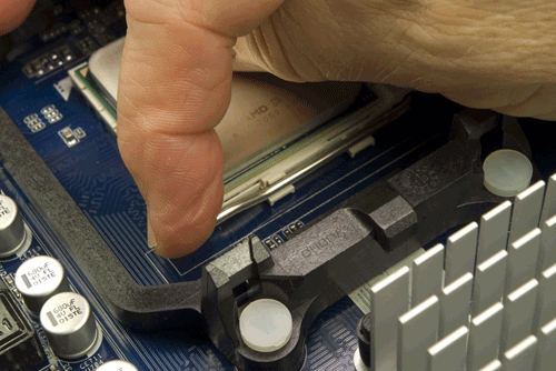
Figure 3-19. Press the cam lever down and snap it into place under the plastic locking tab on the processor socket
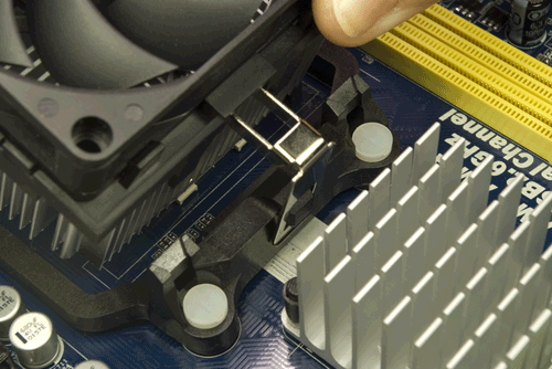
Figure 3-20. Hook the free-floating metal bracket over the black plastic tab on the processor socket
Making sure that the first bracket remains connected and maintaining finger pressure to keep the CPU cooler in position, press the second (cammed) bracket into position over the second tab, as shown in Figure 3-21.
Verify that both brackets are secured over both tabs, and then press the black plastic cam lever down until it latches to lock the CPU cooler to the processor socket, as shown in Figure 3-22.
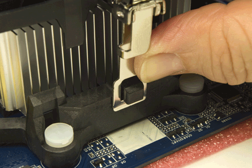
Figure 3-21. Press the latching bracket into position over the second tab
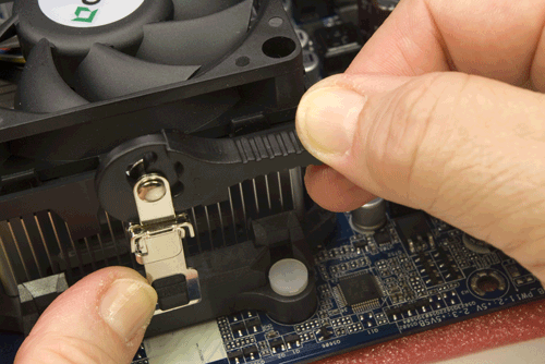
Figure 3-22. Press the black plastic cam lever on the CPU cooler down until it latches to secure the CPU cooler to the processor socket
Ordinarily, we make a point of connecting the CPU cooler fan to the motherboard fan power header pins immediately after installing the CPU cooler, lest we forget to do so. With this motherboard and CPU cooler, though, there’s a slight problem. The length of the CPU fan cable and the location of the CPU fan power connector on the motherboard make it easier to install the memory modules before connecting the fan.
To install the memory modules, open the DIMM locking brackets on both sides of both memory sockets, as shown in Figure 3-23.
Touch the chassis or power supply to ground yourself before you handle the memory modules. Align one DIMM with the memory slot nearest the processor, as shown in Figure 3-24. Make sure the keying notch on the contact edge of the memory module aligns with the keying tab in the socket and that the two sides of the memory module fit into the slots on the vertical sides of the memory slot.
Align the memory module and the slot, with the DIMM vertical relative to the slot and both sides of the DIMM aligned with the vertical slots in the socket. Using both thumbs, press straight down on the memory module until it seats, as shown in Figure 3-25.
Before you install the second memory module, make sure the first module is fully seated and latched. The metal contacts on the base of the memory module should be concealed by the memory socket, and the plastic latching tabs on the memory socket should snap into place to latch the module into position, as shown in Figure 3-26. If the metal contacts on the base of the memory module are visible, the DIMM is not fully seated. Remove it, realign it, and reseat it. If the latching tabs are not seated in the notches on the memory module, it’s possible that the module is not seated completely, but sometimes those latching tabs don’t snap into position even if the module is seated properly. If the metal contacts on the base of the module are not visible and the DIMM otherwise appears to be fully seated, simply use finger pressure to snap the latching tabs into position.
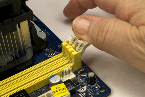
Figure 3-23. Open the DIMM locking tabs on both sides of both memory sockets
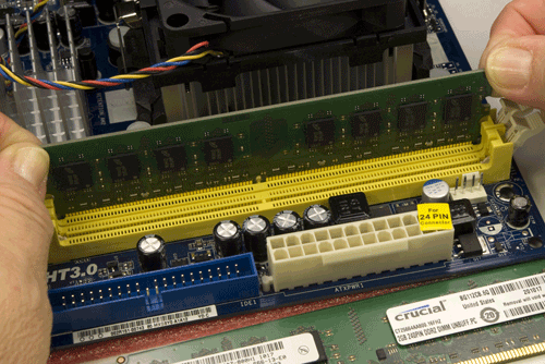
Figure 3-24. Align the memory module with the socket
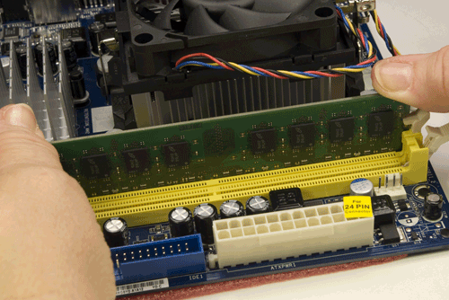
Figure 3-25. Press straight down on both sides of the memory module until it seats completely in the socket
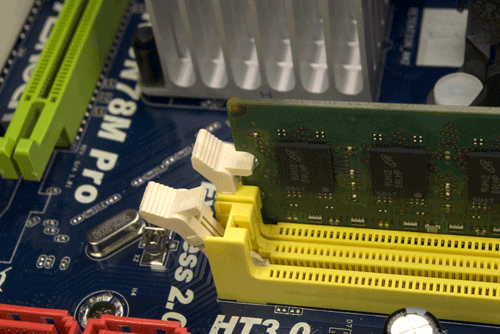
Figure 3-26. Verify that the memory module is latched into position
With the memory installed, you can now connect power to the CPU fan. This connector is keyed by plastic tabs on the cable connector and the motherboard header-pin set to prevent it from being connected incorrectly. Align the cable connector with the header pins and press the cable connector onto the header pins, as shown in Figure 3-27.
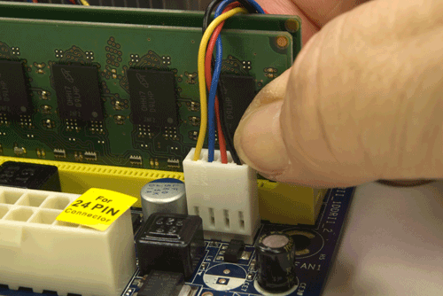
Figure 3-27. Connect the CPU fan power cable to the CPU fan header pins
The motherboard is now prepared. Place it aside for now. Use the antistatic foam under the motherboard to make sure it’s not damaged by static electricity.
Installing the Motherboard
Installing the motherboard is the most time-consuming step in building the system because there are so many cables to connect. It’s important to get all of them connected right, so take your time and verify each connection before and after you make it.
Seating and securing the motherboard
To begin, slide the motherboard into the case, as shown in Figure 3-28. Carefully align the back panel I/O connectors with the corresponding holes in the I/O shield, and slide the motherboard toward the rear of the case until the motherboard mounting holes line up with the standoffs you installed earlier.
One Last Time
Do a final check to make sure there’s a brass standoff installed for each mounting hole, and that no brass standoff is installed where there is no mounting hole.
Before you secure the motherboard, verify that the back panel I/O connectors mate properly with the I/O shield, as shown in Figure 3-29. The I/O shield has metal tabs that ground the back panel I/O connectors. Make sure none of these tabs intrude into a port connector. An errant tab at best blocks the port, rendering it unusable, and at worst may short out the motherboard. Use a flashlight or other bright light to make sure you can see any problem clearly.
Figure 3-28. Slide the motherboard into position
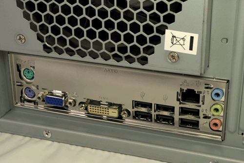
Figure 3-29. Verify that the back panel connectors mate cleanly with the I/O shield
After you position the motherboard and verify that the back panel I/O connectors mate cleanly with the I/O shield, insert a screw through one mounting hole into the corresponding standoff, as shown in Figure 3-30. You may need to apply some pressure to align the motherboard mounting holes with the standoffs until you have inserted two or three screws.
If you have trouble getting all the holes and standoffs aligned, insert two screws in opposite corners but don’t tighten them completely. Use one hand to press the motherboard into alignment, with all holes matching the standoffs. Then insert one or two more screws and tighten them completely. Finish mounting the motherboard by inserting screws into all standoffs and tightening them.
Less Power
People sometimes ask us why we don’t use power screwdrivers. The answer is because they’re large, they’re clumsy, and the batteries are always dead when we want to use them. Worse still, we once watched someone crack a motherboard by overtorquing the mounting screws with a power screwdriver. A clutched driver eliminates that objection, but we still find power screwdrivers too clumsy to use, even when we’re building many identical systems on an ad hoc production line.
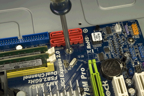
Figure 3-30. Install screws in all six mounting holes to secure the motherboard
With high-quality products like the Antec case and the ASRock motherboard, all the holes usually line up perfectly. With cheap products, that’s often not true. At times, we’ve been forced to use only a few screws to secure the motherboard. We prefer to use all of them, both to physically support the motherboard and to make sure all of the grounding points are in fact grounded, but if you simply can’t get all of the holes lined up, just install as many screws as you can.
Connecting power to the motherboard
With the motherboard installed and secured, the next step is to connect power to the motherboard. In the bundle of cables coming from the power supply, locate the ATX12V cable. Depending on the power supply, this cable may be labeled ATX12V, CPU Power, or something similar. It uses a four-pin (2×2) keyed connector with two 12VDC wires (yellow) and two ground wires (black) diagonally opposite in the connector body. (The Antec power supply actually provides two of these connectors; use one and tuck the other aside.)
Align the ATX12V cable connector with the motherboard ATX12V jack. One side of the cable connector has a plastic latch that snaps over a protruding ledge on the motherboard connector. Make sure those are oriented properly relative to each other and then press the cable connector into the motherboard socket, as shown in Figure 3-31. Make sure the connectors mate and latch.
The next step is to connect the 24-pin ATX main power connector to the motherboard. Locate the main power cable from the bundle coming out of the power supply and route that cable to the front edge of the motherboard. Like the ATX12V connector, the ATX main power connector is keyed and has a latch. Orient the cable connector properly relative to the motherboard socket and press the connector into place, as shown in Figure 3-32. Make absolutely sure that the connectors mate and latch.
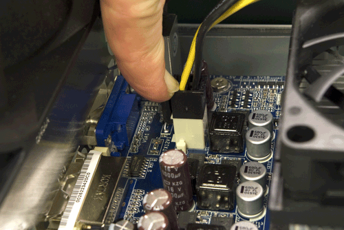
Figure 3-31. Connect the ATX12V power cable (CPU power) to the motherboard
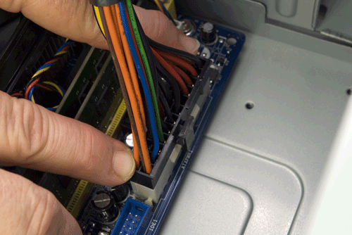
Figure 3-32. Connect the 24-pin ATX main power connector to the motherboard
Connecting front-panel I/O ports
The next step is to connect the front-panel audio and USB ports. Locate the front-panel audio cable. This cable has two connectors, one labeled HD AUDIO and the other AC’97. This motherboard provides an HD audio connector, so we’ll leave the AC’97 connector unused. The audio header pin set is located at the far back corner of the motherboard, colored lime. This connector is keyed with a missing pin on the motherboard header-pin set and a blocked hole on the cable connector. Orient the HD audio cable connector properly, making sure that the missing pin corresponds to the blocked hole, and press the cable connector onto the header-pin set, as shown in Figure 3-33.
The front-panel USB cable supports two front-panel USB ports. This cable connects to either of the two sets of USB header pins (color-coded blue) located in the front corner of the motherboard near the expansion slots. Like the audio connector, the USB connector is keyed with a missing pin on the motherboard header-pin set and a corresponding blocked hole on the cable connector. Align and orient the USB cable connector properly relative to the motherboard USB header-pin set, and press the cable connector onto the header pins, as shown in Figure 3-34.
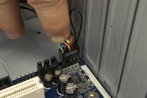
Figure 3-33. Connect the front-panel HD audio cable to the motherboard
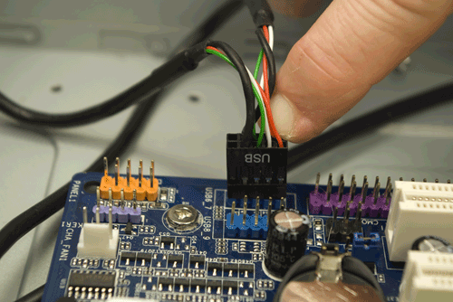
Figure 3-34. Connect the front-panel USB cable to the motherboard
Connecting front-panel switch and indicator cables
The next step is to connect the front-panel switch and indicator cables to the motherboard. Before you begin connecting front-panel cables, examine the cables. Each is labeled to indicate its purpose. Match those labels with the front-panel connector pins on the motherboard to make sure you connect the correct cable to the appropriate pins. Once you determine the proper orientation for each cable, connect it as shown in Figure 3-35.
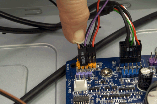
Figure 3-35. Connect the front-panel switch and indicator cables
Keep the following guidelines in mind as you connect the front-panel cables:
- Although Intel has defined a standard front-panel connector block and uses that standard for its own motherboards, few other motherboard makers adhere to that standard. Accordingly, rather than providing an Intel-standard monolithic connector block that would be useless for motherboards that do not follow the Intel standard, most case makers, including Antec, provide individual one-, two-, or three-pin connectors for each switch and indicator.
- Not all cases have cables for every connector on the motherboard, and not all motherboards have connectors for all cables provided by the case.
- The power switch and reset switch connectors are not polarized and can be connected in either orientation.
- LED connectors are polarized and should be connected with the ground wire and the signal wire oriented correctly. Most cases use a common wire color—usually black, although sometimes white or green—for ground, and a colored wire for signal.
- The power LED connector is often problematic, as it is for this system. There are two types of power LED connector. The first has two pins. The second has three pins, but only two wires, with the middle pin unused. A motherboard may provide either or both types of power LED connector, and a case may provide either or both types of power LED cable. The ASRock K10N78M-PRO motherboard provides only a two-pin power LED connector. The Antec NSK-4482 case provides only a three-pin power LED cable. That leaves us with two options. We took the easy way out by simply leaving the power LED disconnected. If you want your power LED to function, use a sharp knife or diagonal cutters to carefully cut the power LED cable connector lengthwise, dividing it into two single-wire connectors. Connect each of those separately to the two power LED pins on the motherboard.
Advice from Brian Bilbrey
I prefer to use a knife tip to gently release (not break off) the plastic tab holding one of the end pins in the cable connector body in place, then slide that pin out and move it to the center location. Then I can install the connector onto the header with the empty location hanging out in space.
- The power LED connectors on some motherboards are dual-polarized and can support a single-color (usually green) power LED or a dual-color (usually green/yellow) LED. The Antec NSK-4482 case and the ASRock K10N78M-PRO motherboard both support only a single-color power LED. If you are using a different case and motherboard that support a dual-color power LED, check the case and motherboard documentation to determine where and how to connect the power LED cable.
When you’re connecting front-panel cables, try to get it right the first time, but don’t worry too much about getting it wrong. Other than the power switch cable, which must be connected properly for the system to start, none of the other front-panel switch and indicator cables is essential, and connecting them wrong won’t damage the system.
Connecting drive power and data cables
We’re in the final stretch now. All that remains is to connect a few cables. To begin, connect two SATA data cables to SATA ports 0 and 1 on the motherboard, as shown in Figure 3-36. We’ll use one of these cables for the optical drive and the other for the hard drive.
Which Is Which?
On systems with several hard drives, we use a felt-tip pen to label both ends of each SATA data cable to make it easier to determine which cable connects to which drive. For this system, with only one hard drive, that’s not necessary. We also used cables with different connector shells, making it immediately obvious which cable connects to which drive.
Locate an available SATA power cable in the cable bundle coming from the power supply and connect it to the power connector on the optical drive. SATA power (and data) cables use an L-shaped key on the connector body to prevent installing the cables backward. Make sure the L is oriented properly on the cable and drive, and then press the connector into place, as shown in Figure 3-37. Press the connector firmly straight in until you’re sure the connector is fully seated. Do not apply any sideways pressure or torque to the connector.
Locate the free end of SATA data cable 1 and press the connector onto the optical drive data connector, as shown in Figure 3-38. Once again, make sure the L key is oriented properly on the cable and drive, and then press the connector firmly straight in until the connector is fully seated.
Locate a SATA power cable in the cable bundle coming from the power supply. You can use a second SATA power connector on the same cable you connected to the optical drive or one of the separate cables with a SATA power connector. Make sure the L key is oriented properly on the cable and hard drive, and then press the SATA power connector into place, as shown in Figure 3-39. Press the connector straight in without applying any sideways pressure, and make sure the cable connector mates firmly with the drive connector.
Locate the free end of SATA data cable 0 and press the connector onto the hard drive data connector, as shown in Figure 3-40.
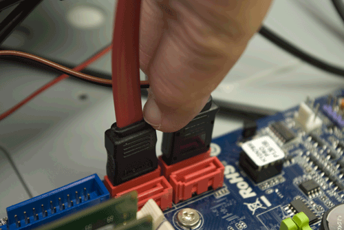
Figure 3-36. Connect the SATA data cables for the hard drive and optical drive to motherboard SATA ports 0 and 1
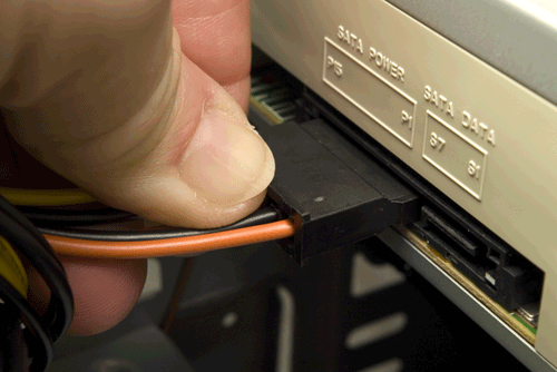
Figure 3-37. Connect a SATA power cable to the optical drive
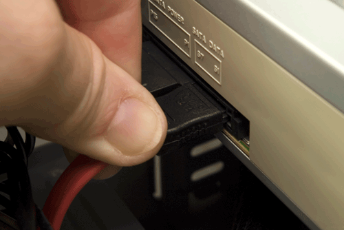
Figure 3-38. Connect SATA data cable 1 to the optical drive
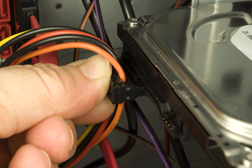
Figure 3-39. Connect a SATA power cable to the hard drive
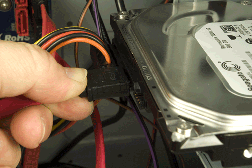
Figure 3-40. Connect SATA data cable 0 to the hard drive
Final Assembly Steps
Congratulations! You’re almost finished building the system. Only a couple of final steps remain to be done, and these won’t take long.
First, connect the supplemental case fan.
The Antec NSK-4482 has one rear-mounted 120 mm supplemental fan. To enable it, connect a four-pin Molex connector from the power supply to the connector on the fan, as shown in Figure 3-41.
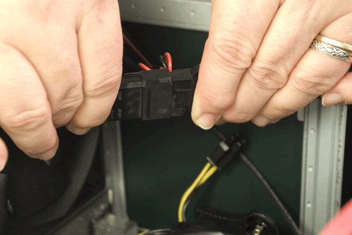
Figure 3-41. Connect power to the rear case fan
The final step in assembling the system is to dress the cables. That simply means routing the cables away from the motherboard and other components and tying them off so they don’t flop around inside the case. Chances are that no one but you will ever see the inside of your system, but dressing the cables has several advantages other than making the system appear neater. First and foremost, it improves cooling by keeping the cables from impeding air flow. It can also improve system reliability. More than once, we’ve seen a system overheat and crash because a loose cable jammed the CPU fan or case fan.
After you’ve completed these steps, take a few minutes to double-check everything. Verify that all cables are connected properly, that all drives are secured, and that there’s nothing loose inside the case. It’s a good idea to pick up the system and tilt it gently from side to side to make sure there are no loose screws or other items that could cause a short. Also, check one last time that the power supply is set for the correct input voltage. Use the following checklist:
Power supply set to proper input voltage (if applicable)
No loose tools or screws (tilt and shake the case gently)
Heatsink/fan unit properly mounted; CPU fan connected
Memory module(s) fully seated and latched
Front-panel switch and indicator cables connected properly
Front-panel USB cable connected properly
Hard drive data cable connected to drive and motherboard
Hard drive power cable connected
Optical drive data cable connected to drive and motherboard
Optical drive power cable connected
All drives secured to drive bay or chassis, as applicable
Expansion cards (if any) fully seated and secured to chassis
Main ATX power cable and ATX12V power cable connected
Case fan(s) installed and connected (if applicable)
All cables dressed and tucked
Once you’re certain that all is as it should be, it’s time for the smoke test. Leave the cover off for now. Unlike many power supplies, the Antec EarthWatts has a separate rocker switch on the back that controls power to the power supply. By default, it’s in the “0” or off position, which means the power supply is not receiving power from the wall receptacle. Ensure the rocker switch is off, then connect the power cable to the wall receptacle and then to the system unit. Next, flip the power supply switch to the “1” or on position. Press the main power button on the front of the case, and the system should start up. Check to make sure that the power supply fan, CPU fan, and case fan are spinning. You should also hear the hard drive spin up. At that point, everything should be working properly.
False Starts
When you turn on the rear power switch, the system will come to life momentarily and then die. That’s normal behavior. When the power supply receives power, it begins to start up. It quickly notices that the motherboard hasn’t told it to start, though, so it shuts down again. All you need to do is press the front-panel power switch and the system will start normally.
Final Words
This system assembled easily and quickly. If we hadn’t had to shoot images, it probably would have taken us about 20 minutes to build. A first-time system builder should be able to assemble this system in an hour or so, and certainly over the course of an evening.
We’re extremely happy with this system, or perhaps we should say that Barbara’s sister is extremely happy with it. Although it cost only $350 excluding the display and software, many people would be happy with this system as their only system. It’s slower than the fastest current systems, but it’s more than fast enough for casual use, including even light gaming. It’s also quiet enough that we wouldn’t hesitate to use it in our den, living room, or bedroom.
Although we didn’t think about it until we’d already given the system to Barbara’s sister, with some minor additions such as a larger hard drive or drives this would also make an excellent poor man’s media center system. The system is quiet enough to be unobtrusive in a typical den or home-theater room, and the black micro-tower case won’t clash visually with most AV setups. The processor and video are both fast enough to deal with full 1080p HD video via the DVI output, and the system has slots available if you want to add a tuner card or cards.
All in all, this turned out to be a perfect budget PC.