8. Building a Home Server
A home server is a computer located in a private residence that is dedicated to providing file sharing and other centralized services to other computers within that residence. A home server may also provide virtual private network (VPN) service or password-controlled access to allow authorized people to access server resources remotely via the Internet. Some home servers are configured as public-facing Internet hosts that run web servers, mail servers, or other services open to the Internet at large.
Media Center System Versus Home Server
Although they appear superficially similar, there are significant differences between a media center system and a home server. Both store files, but there the similarity ends.
A media center system sits front and center in the den or living room and is used interactively in much the same way as a desktop system, albeit usually from across the room. Size, noise level, and appearance are important, and disk storage is typically fairly limited.
A home server usually sits in a closet or buried under a desk somewhere, and is seldom if ever used interactively. Size, noise level, and appearance are generally less important for a server, and the amount of disk storage it supports is massive. For example, our media center system has two hard drives, for a total of 4 TB of disk space; our home server will eventually host eight hard drives, with a total of 24 TB of disk space. It may also host several eSATA external hard drives for even more disk space.
You can, of course, combine the functions of these two systems, building a media center system with lots of disk space, and also using it as a general-purpose home server. The drawback is that you'll need to use a much larger (and likely louder) case, which many people would find unacceptable in their dens or living rooms.
By the mid to late '90s, all the necessary pieces were in place for home networking to take off. Many households had two or more computers (and wanted to share their printers and other expensive peripherals), networking hardware had become affordable, and Windows 95 and 98 made it easy to set up a home network. Finally, always-on DSL or cable broadband Internet access was becoming common, and many people wanted to share that fast Internet connection with all of the computers in the house.
These early home networks were almost invariably peer-to-peer. All or most of the computers in a home network shared disk storage and other resources with all of their peers. Almost no one used a dedicated server, because PCs were still relatively expensive and setting up a server-based network was much more complicated than simply sharing resources on a peer network.
That started to change, almost by accident, as more and more people bought new PCs to replace older models. Some people donated their old computers to charities or simply discarded them, of course, but many decided to run those old systems as dedicated home servers, perhaps installing larger hard drives to provide more shared disk space.
Even today, a repurposed older system is by far the most common type of home server. That's unfortunate, because an old system is about the worst possible choice for a home server. Granted, a typical home server doesn't require much processor horsepower, but that's about the only way an older system is suited to be a home server.
Think about it. You'll probably load up your home server with gobs of data that really matter to you: irreplaceable digital camera images and home video footage, your pr0n collection, all of your documents, your old tax returns and business records, and so on. Do you really want all of that precious information residing on a system that's near the end of its design life, with a five-year-old motherboard and power supply? That's a disaster waiting to happen.
Fortunately, it doesn't cost much to build a new home server, one that uses new components and is designed for reliability. You don't need much in the way of processor performance, so even a budget processor will suffice. You don't need a motherboard with high performance or a lot of features, so again even a budget model is suitable. You don't need much memory. You don't need a fancy case—in fact you can even recycle that old case (but not the power supply). You don't even need a display, keyboard, and mouse, because you can run your new server headless (without a keyboard, mouse, or display). Even an optical drive is optional.
You will need to spend some money on the important stuff: a good power supply, an extra case fan (or two or three...), a large hard drive or two (or three or four...), and a good backup power supply (BPS) or uninterruptible power supply (UPS). You may also need to spend some money on backup hardware. But in return you'll get a rock-solid reliable data repository that you can trust to keep your priceless data safe.
Determining Functional Requirements
We began by sitting down to think through our requirements for a home server. Here's the list of functional requirements we came up with:
Reliability
First and foremost, the home server must be reliable. Our server will run 24/7/365, and yours probably will, too. Other than periodic downtime to blow out the dust, upgrade hardware, and so on, we expect our server to Just Work without us having to think about it.
Massive storage capacity
In the past, we routinely used lossy compression formats like JPEG and MPEG to cut down file sizes. The problem with lossy compression is that, by definition, it loses data relative to the original source format. We want to store our digital camera images as RAW files, our camcorder video as DV files, and our scans of old photographs as lossless TIFFs. Some of those source formats are themselves compressed with lossy algorithms, so the last thing we want to do is lose still more data by converting them to something lossier still.
Modern digital AV devices produce a huge amount of data. For example, we accumulated more than 20 GB of data just shooting RAW digital camera images for this book. Our SD DV camcorder records about 13.5 GB/hour. We intend to upgrade to an HD camcorder, which boosts storage requirements to about 40 GB/hour. (Raw HD footage can be captured at about 185 MB/second, if you have a drive array fast enough to keep up.) We have hundreds of family photographic prints, some dating from the mid to late 19th century. Scanning just one of those at high resolution may require 50 MB or more of disk space, as may scanning just one of our 35 mm color slides or negatives at 4,000 DPI, even using lossless compression.
And then there's our collection of ripped CD-Audio and DVD-Video discs. All of them are stored on our media center system and we also have the original discs, so at first glance it might seem wasteful to store copies on our home server. But that ignores the time and effort we put in ripping all those discs in the first place. We really don't want to have to re-rip hundreds and hundreds of discs if a hard drive fails in our media center system.
In short, we have a ton of data, so we need a ton of disk space on our server. We decided that 6 TB (6,000 GB) would suffice, at least to get started. You might not have as much data as we do, but you probably have a lot more than you think. Consider your own current and future storage requirements carefully before you configure your home server.
Data safety
We've never lost any data other than by our own stupidity, and we want to keep it that way. Accordingly, you might expect that we'd configure our home server with RAID storage. We didn't. Here's why.
Using RAID can increase storage performance on a heavily loaded server, and it allows data to be recovered if a hard drive fails. Although it may sound odd, neither of those benefits is particularly important to us. A modern SATA hard drive is fast enough to saturate our 1000BaseT (gigabit) Ethernet network all by itself, so we don't need higher disk performance. And hard drive failures are so rare that it's simply not worth worrying about them.
Because RAID doesn't protect against the more common causes of data loss—accidental deletion, data being corrupted by a virus or malfunctioning hardware, or catastrophic loss caused by theft or fire—we'd still need to maintain backups even if we had a full RAID storage system. Given that we back up frequently—when we're actively creating new data, we often do differential backups several times a day—the only thing that using RAID would buy us is a very limited protection against losing a very small amount of un-backed-up data, and that only in the event of a hard drive failure.
Ultimately, we decided that the small benefits weren't worth the additional cost and complexity of installing RAID. We decided to use nonredundant SATA hard drives in our home server. By giving up the small additional safety factor provided by RAID, we'll gain more available hard disk space and free up at least a couple of drive bays that can be used for later expansion.
Flexibility
Initially, our home server will be almost exclusively a file server. It will run Linux, though, so at some point we may decide to add other functions to the home server. To allow for that possibility with minimum disruption, we'll configure the server initially with enough processor and memory to allow adding functions incrementally without upgrading the hardware.
Expandability
When we set out to design our new home server, we considered building it as an appliance system with an Intel Atom Mini-ITX board in a tiny case. There are advantages to such a server. It's small and can be put anywhere, and it doesn't consume much power, produces little heat, and doesn't make much noise.
But we soon realized that for us the lack of flexibility inherent in a small system outweighed its advantages. Looking back on how our last server had grown and changed over the years made it clear that we wanted a larger form factor for our new server.
Our last server was built in 2006, and originally had four 500 GB drives installed, for a total of 2 TB of disk storage. We reached that storage limit within a year, a lot faster than we'd expected. As a stopgap, we installed a 750 GB drive, for a total of five drives and 2.75 TB. As drive prices continued to fall, we replaced or added drives until we eventually ended up with four 1 TB drives installed, and a total of 4 TB of storage. (We recycled the 500 and 750 GB drives as external hard drives for backups.)
That was where things stood when we set out to design and build our new server. With 4 TB, we still had some available space, but the trend was clear. The largest available hard drives when we designed our new server were 2 TB, so we decided to start with three of those, for a total of 6 TB. But we knew our storage requirements would continue to grow, so we wanted a system that we could expand to at least six or eight hard drives. With 3 TB drives on the near horizon, that means we can eventually expand this server to a capacity of between 18 TB and 24 TB, which should hold us for a while. (We're sure that in a few years we'll look back with amusement on the days when we thought 24 TB was a lot of disk space.)
Networking
Of course, a server is useless if you can't get data into and out of it, so we need fast, reliable networking support. Our current home network is a mix of 100BaseT (100 Mb/s) and 1000BaseT (1,000 Mb/s, "gigabit") Ethernet devices that we're currently in the process of upgrading to exclusively 1000BaseT. We've complained elsewhere about the 25 MB/s throughput of USB 2.0, and, at about 10 MB/s, 100BaseT is even worse. A 1000BaseT network transfers data at about 100 MB/s, or about the same rate as a fast hard drive. That's acceptably fast for our purposes, so we'll choose a motherboard that supports 1000BaseT Ethernet.
Hardware Design Criteria
With the functional requirements determined, the next step was to establish design criteria for the home server hardware. Here are the relative priorities we assigned for our home server. Your priorities may, of course, differ.
|
Price |
★★★✩✩ |
|
Reliability |
★★★★✩ |
|
Size |
★★✩✩✩ |
|
Noise level |
★★★✩✩ |
|
Expandability |
★★★✩✩ |
|
Processor performance |
★★✩✩✩ |
|
Video performance |
✩✩✩✩✩ |
|
Disk capacity/performance |
★★★★✩ |
Here's the breakdown:
Price
Price is moderately important for this system. We don't want to spend money needlessly, but we will spend what it takes to meet our other criteria.
Reliability
Reliability is the single most important consideration. If this system goes down, we're out of action until we can get it running again. We didn't award this category five stars because we don't have the budget to build a professional-grade server with expensive features like dual-failover motherboards or redundant power supplies.
Size
Size is relatively unimportant. Our home server will reside under the desk in Robert's office, which has enough room for a mid-tower system. (A full tower would be pushing it.)
Noise level
Noise level is unimportant for a server that sits in a server room, but in a residence it may be critical. Because the home server will be installed in Robert's office, it's important to keep the noise level relatively low. We'll choose quiet standard components, but not expensive "Quiet PC" technologies.
Expandability
Expandability is moderately important. Our server will initially have four hard drives installed, but we may want to expand the storage subsystem later. Similarly, although we'll use the integrated SATA and network interfaces initially, we may eventually install additional disk adapters, network interfaces, and so on.
Processor performance
Processor performance is relatively unimportant. Our home server will run Linux for file sharing, which places little demand on the CPU. However, the server may eventually run some server-based applications. The incremental cost of installing a budget dual-core processor and sufficient memory to support those possible software upgrades is small enough that we'll do it now and have done with it.
Video performance
Video performance is of literally zero importance, because we'll run our home server headless. That is, we'll temporarily install a monitor while we install and configure Linux, but we'll subsequently manage the server from a desktop system elsewhere on the network. We'll either use a motherboard with integrated video, or install a video card for just long enough to get Linux installed and working.
Disk capacity/performance
Disk capacity and performance are very important. Our home server will have only one or two simultaneous users, so standard 7,200 RPM SATA hard drives will provide more than adequate performance. Capacity is the more important consideration for our server. We want 6 TB of hard disk space initially, and we'd like to be able to expand that to 12 TB or more without making major changes to the case or the existing drive subsystem. That means we'll need to use relatively few high-capacity hard drives instead of many lower-capacity drives.
RAID for Home Servers
Although we elected not to use RAID on our home server, that doesn't mean RAID isn't right for your home server. RAID is an acronym for Redundant Array of Inexpensive Disks. A RAID stores data on two or more physical hard drives, thereby reducing the risk of losing data when a drive fails. Some types of RAID also increase read and/or write performance relative to a single drive.
![]() RAID is NOT Backup
RAID is NOT Backup
We can't say it often enough. RAID does not substitute for backing up. RAID protects against data loss as a result of a drive failure, and may increase performance. But RAID does not and cannot protect against data loss or corruption caused by viruses, accidental or malicious deletions, or catastrophic events such as a fire, flood, or theft of your server.
Five levels of RAID are formally defined, RAID 1 through RAID 5. (Some manufacturers sell proprietary arrays that they describe as RAID 1.5, RAID 5E, RAID 5EE, RAID 6, RAID 7, RAID DP, RAID K, RAID S, RAID Z, and so on, but those are merely enhanced versions of one of the standard RAID levels.)
Brian Bilbrey Comments
RAID 6 is actually more than just RAID 5 with another parity stripe. It's usually configured with a different checksum algorithm, to protect against algorithmic weakness. In addition, with the real possibility of a bit error during a rebuild following drive loss, I'd consider RAID 6 to be required when individual drives of 750 GB or larger are used.
RAID levels are optimized to have different strengths, including level of redundancy, optimum file size, random versus sequential read performance, and random versus sequential write performance. RAID 1 and RAID 5 are commonly used in PC servers. RAID 3 is used rarely (generally for streaming video). RAID 2 and RAID 4 are almost never used. The RAID levels typically used on home servers are:
RAID 1
RAID 1 uses two drives that contain exactly the same data. Every time the system writes to the array, it writes identical data to each drive. If one drive fails, the data can be read from the surviving drive. Because data must be written twice, RAID 1 writes are a bit slower than writes to a single drive. Because data can be read from either drive in a RAID 1, reads are somewhat faster. RAID 1 is also called mirroring, if both drives share one controller, or duplexing, if each drive has its own controller.
RAID 1 provides very high redundancy, but it is the least efficient of the RAID levels in terms of hard drive usage. For example, with two 2 TB hard drives in a RAID 1 array, only 2 TB of total disk space is visible to the system. RAID 1 may be implemented with a physical RAID 1 controller or in software by the operating system.
RAID 5
RAID 5 uses three or more physical hard drives. The RAID 5 controller divides data that is to be written to the array into blocks and calculates parity blocks for the data. Data blocks and parity blocks are interleaved on each physical drive, so each of the three or more drives in the array contains both data blocks and parity blocks. If any one drive in the RAID 5 fails, the data blocks contained on the failed drive can be re-created from the parity data stored on the surviving drives.
RAID 5 is optimized for the type of disk usage common in an office environment—many random reads and fewer random writes of relatively small files. RAID 5 reads are faster than those from a single drive, because RAID 5 has three or more spindles spinning and delivering data simultaneously. RAID 5 writes are typically a bit faster than single-drive writes. RAID 5 uses hard drive space more efficiently than RAID 1.
In effect, although RAID 5 uses distributed parity, a RAID 5 array can be thought of as dedicating one of its physical drives to parity data. For example, with three 2 TB drives in a RAID 5 array, 4 TB—the capacity of two of the three drives—is visible to the system. With RAID 5 and four 2 TB drives, 6 TB—the capacity of three of the four drives—is visible to the system. RAID 5 may be implemented with a physical RAID 5 controller or in software by the operating system. Few motherboards have embedded RAID 5 support.
RAID 3
RAID 3 uses three or more physical hard drives. One drive is dedicated to storing parity data, with user data distributed among the other drives in the array. RAID 3 is the least common RAID level used for PC servers, because its characteristics are not optimal for the disk usage patterns typical of small office LANs. RAID 3 is optimized for sequential reads of very large files, so it is used primarily for applications such as streaming video.
Then there is the so-called RAID 0, which isn't really RAID at all because it provides no redundancy:
RAID 0
RAID 0, also called striping, uses two physical hard drives. Data written to the array is divided into blocks, which are written alternately to each drive. For example, if you write a 1 MB file to a RAID 0 that uses 256 KB blocks, the first 256 KB block may be written to the first drive in the array. The second 256 KB block is written to the second drive, the third 256 KB block to the first drive, and the final 256 KB block to the second drive. The file itself exists only as fragments distributed across both physical drives, so if either drive fails all the data on the array is lost. That means data stored on a RAID 0 is more at risk than data stored on a single drive, so in that sense a RAID 0 can actually be thought of as less redundant than the zero redundancy of a single drive. RAID 0 is used because it provides the fastest possible disk performance. Reads and writes are very fast, because they can use the combined bandwidth of two drives. RAID 0 is a poor choice for desktops and workstations, which typically do not load the disk subsystem heavily enough to make RAID 0 worth using. Heavily loaded servers, however, can benefit from RAID 0 (although few servers use bare RAID 0 because of the risk to the data stored on a RAID 0 array).
Finally, there is stacked RAID, which is an "array of arrays" rather than an array of disks. Stacked RAID can be thought of as an array that replaces individual physical disks with subarrays. The advantage of stacked RAID is that it combines the advantages of two RAID levels. The disadvantage is that it requires a lot of physical hard drives:
Stacked RAID
The most common stacked RAID used in PC servers is referred to as RAID 0+1, RAID 1+0, or RAID 10. A RAID 0+1 uses four physical drives arranged as two RAID 1 arrays of two drives each. Each RAID 1 array would normally appear to the system as a single drive, but RAID 0+1 takes things a step further by creating a RAID 0 array from the two RAID 1 arrays. For example, a RAID 0+1 with four 2 TB drives comprises two RAID 1 arrays, each with two 2 TB drives. Each RAID 1 is visible to the system as a single 2 TB drive. Those two RAID 1 arrays are then combined into one RAID 0 array, which is visible to the system as a single 4 TB RAID 0. Because the system "sees" a RAID 0, performance is very high. And because the RAID 0 components are actually RAID 1 arrays, the data are very well protected. If any single drive in the RAID 0+1 array fails, the array continues to function, although redundancy is lost until the drive is replaced and the array is rebuilt.
RAID 1 Versus RAID 0+1
If your storage subsystem has four hard drives, there is no point to using RAID 1 rather than RAID 0+1, assuming that your motherboard or RAID adapter supports RAID 0+1. A RAID 1 uses two of the four drives for redundancy, as does the RAID 0+1, so you might just as well configure the drives as a RAID 0+1 and get the higher performance of RAID 0+1. Either RAID level protects your data equally well.
Until a few years ago RAID 0+1 was uncommon on small servers because it required SCSI drives and host adapters, and therefore cost thousands of dollars to implement. Nowadays, thanks to inexpensive SATA drives, the incremental cost of RAID 0+1 is very small. Instead of buying one $200 hard drive for your small server, you can buy four $100 hard drives and a $50 RAID adapter. You may not even need to buy the RAID adapter, because some motherboards include native RAID 0+1 support. Data protection doesn't come much cheaper than that.
Hardware Versus Software Versus Hybrid RAID
RAID can be implemented purely in hardware, by adding an expansion card that contains a dedicated RAID controller, processor, and cache memory. Hardware RAID, if properly implemented, offers the highest performance and reliability and places the fewest demands on the main system processor, but is also the most costly alternative. True hardware RAID adapters cost several hundred dollars and up, and are generally supplied with drivers for major operating systems (including Windows and Linux).
Software RAID requires only standard ATA or SATA interfaces, and uses software drivers to perform RAID functions. In general, software RAID is a bit slower and less reliable than hardware RAID and places more demands on the main system processor. Most modern operating systems, including Windows and Linux, support software RAID—usually RAID 0, RAID 1, and RAID 5—and may also support RAID 0+1. We believe that well-implemented software RAID is more than sufficient for a typical home server, if indeed RAID is desirable at all.
Hybrid RAID combines hardware and software RAID. Hybrid RAID hardware does not contain the expensive dedicated RAID processor and cache memory. Inexpensive RAID adapters have limited or no onboard processing, and instead depend on the main system processor to do most or all of the work. With very few exceptions, motherboards that feature onboard RAID support, such as Intel models, use hybrid RAID, although it is sometimes incorrectly called hardware RAID. If you choose a hybrid RAID solution, make certain that drivers are available for your operating system.
And what if you choose not to use any form of RAID, as we did? We decided to install three 2 TB drives in our home server, configured as a JBOD (Just a Bunch of Drives). All three drives function independently as ordinary drives, and we get the full 6 TB combined capacity of the three drives. If we installed a fourth 2 TB drive, we could choose any of the following disk configurations without making any hardware changes:
JBOD
All four drives operate independently. With four 2 TB drives, the operating system "sees" 8 TB of disk capacity. Performance and data safety are determined by the performance and reliability of the individual drives. Note that a drive failure is four times as likely to occur with four drives spinning than it is when only one drive is spinning. If a drive fails, you lose whatever data was stored on that drive, but the data on other drives is not affected.
Brian Jepson Comments
I'd argue that the likelihood is some (probably small) value greater than four times more likely, given that additional drives add heat and vibration. I'm reminded of Brendan Gregg's experiment in the effect of noise on JBOD arrays: http://blogs.sun.com/brendan/entry/unusual_disk_latency.
My favorite moment comes at 0:59 when he looks like he's about to say something and then goes right back to the array.
RAID 5
All four drives are assigned to the RAID 5. The operating system sees 6 TB of disk capacity. (The equivalent of one drive's capacity is used to store parity data, although that data is actually distributed across all four drives.) Read and write performance for small files is the same or slightly faster than with individual drives. Read and write performance for large files is slightly slower than with individual drives. RAID 5 offers moderate redundancy. Any one drive may fail without loss of data. If two drives fail simultaneously, all data on the array will be lost.
RAID 10
All four drives are assigned to the RAID 10, as in effect a RAID 0 pair of RAID 1 mirrored drives. The operating system sees 4 TB of disk capacity. Read performance for any size file is noticeably faster than with JBOD or RAID 5, particularly when the drives are heavily loaded. Write performance is also faster. RAID 10 offers very high redundancy. Any two drives may fail without loss of data, as long as they are not both members of the same RAID 1. If both drives in a RAID 1 fail simultaneously, all data on the array will be lost.
With the hardware configuration we detail later in this chapter, you can choose any of these disk configurations during setup. You don't even need to pop the lid or move any cables. But give some serious thought to which configuration to use. If you change your mind later, you can reconfigure the disk subsystem, but you'll need to back up all of your data and restore it after you set up the new configuration.
Brian Bilbrey Comments
Given the time needed to repopulate the data after acquiring another drive, I'd almost certainly put five or six 2 TB drives in a RAID 6 configuration, rather than just using JBOD. My time has value, too.
If I were optimizing a server for write performance, I'd mirror RAID 0 arrays of two or three drives each to yield maximum performance with mirroring protection, but without the parity calculation overhead.
Note that I'm running 3Ware (now LSI) hardware RAID without a battery backup in my home server/workstation today. I'm currently undecided about the next generation. This chapter should help inform my decision.
Component Considerations
With our design criteria in mind, we set out to choose the best components for our home server system. The following sections describe the components we chose, and why we chose them.
![]() Your Mileage May Vary
Your Mileage May Vary
Although we tested the configuration we used to build our own home server, we did not test permutations with all the listed alternatives. Those alternatives are simply the components we would have chosen had our requirements been different. That said, we know of no reason the alternatives we list should not work perfectly.
Case and Power Supply
Antec Atlas 550 Server Case (http://www.antec.com)
A home server can be built in anything from a tower case specifically designed to house servers down to the smallest of small form factor cases. True server cases are usually large, heavy, and expensive—overkill for a typical home server. Very small cases may be suitable for some home servers, but their lack of drive bays and low-output power supplies often rule them out.
For our home server, the ideal case must be reasonably priced, be equipped with a top-quality power supply of 500W or more, have at least six or eight drive bays—ideally, with provisions to soft-mount hard drives for higher reliability—and have enough fans (or fan positions that we can populate) to provide high cooling efficiency. We'd also like the case to be attractive and reasonably quiet.
More Power
Why a 500W power supply? Even if we load this system to the gills with hard drives and other peripherals, a 350W power supply would probably be adequate.
For 20 years or more, we've overspecced power supplies in servers because we want the power supply to run at half or less of its rated capacity. The downside is that a lightly loaded power supply is slightly less efficient in terms of power consumption. The upside is that a lightly loaded power supply produces cleaner power and runs much cooler, which greatly extends its expected service life.
The key considerations for a home server case are the number of drive bays it provides and its cooling efficiency. In a residential environment, noise level and appearance may also be important. For us, all four of those factors were important. We wanted at least half a dozen hard drive bays to accommodate our initial disk configuration while leaving drive bays available for future expansion. Effective cooling is critical for obvious reasons. Noise level is important because this server will live in Robert's office, which already has several computers contributing to the noise level. Appearance is important because Robert doesn't want an ugly box sitting in his office.
We budgeted $140 to $160 for the case and power supply, because a top-quality 500W or better power supply costs at least $80 and a suitable case at least $60. That ruled out several otherwise suitable server cases from Intel and Super Micro that were priced considerably higher. If our budget could have extended to $200 or more, we'd have seriously considered models like the Antec Titan 650, the Intel SC5299UPNA, and the Super Micro CSE-733i-645.
![]() Case, Yes. Power Supply, No.
Case, Yes. Power Supply, No.
If you intend to recycle an old case as your new home server, we strongly recommend that you replace the power supply and case fans. Even top-quality power supplies and case fans have a design life, typically five years, and the lower-quality power supplies and fans used in mass-market systems may well be on their last legs after only two or three years of use. While you're at it, consider adding case fans if there are unused fan positions in your case. The more air you have moving through the system, the cooler it will run and the more reliable it will be.
In the $150 price range, the Antec Atlas 550 is the standout choice, so much so that we couldn't find any comparable cases at anything close to its price. Despite its mini-tower form factor, the Atlas 550 provides a total of eight drive bays—four external 5.25" bays and four internal 3.5" bays—and accepts full ATX (although not extended ATX) motherboards. Only the four internal bays have shock mounts for the hard drives, but if we want to install drives in the external bays we can use silicone washers from the hardware store.
In stock form, the Atlas 550 has very good cooling. In addition to the power supply fan, a three-speed 120 mm rear fan is standard. There are also three open fan positions, for one 80 mm fan on the side panel and two front 92 mm fans to cool the hard drives. Frankly, we're not sure why Antec didn't just include those two 92 mm fans as a standard feature.
The Atlas 550 is a reasonably quiet case, particularly if you run the case fans at less than full speed. The TruPower power supply is nearly inaudible, particularly running lightly loaded. Appearance is obviously a matter of taste, but we think the Atlas 550 is a very attractive case. We wouldn't hesitate to use it in our den, library, or living room, let alone our offices.
Motherboard and Processor
ASRock K10N78M Pro (http://www.asrock.com)
AMD Athlon II X2 240 (http://www.amd.com)
Most home servers spend most of their time reading, writing, transmitting, and receiving files, none of which places much burden on a processor. Other than stability and reliability, the only requirements for the motherboard are that it supports at least a couple of gigabytes of memory, provides ports for connecting at least the three SATA hard drives we plan to install initially, and provides at least one fast, reliable Ethernet port. Of course, even a motherboard that lacks those ports can be expanded by adding PCI or PCI Express adapter cards to increase the port count.
In fact, we seriously considered using an inexpensive Intel Atom motherboard/processor combo for our home server. We decided not to, but only because Atom motherboards are short of both ports and expansion slots. Instead, we decided to use the same processor and motherboard we used in the budget system. (Why reinvent the wheel?) That boosted our cost for the motherboard and processor from $80 or so for the Intel Atom motherboard/processor to $120 or so for the budget motherboard/processor, less the cost of the $15 expansion card we'd have had to add to provide more SATA ports.
That $25 or so extra was well worth spending. Rather than a tiny motherboard with very limited expansion capabilities, we ended up with a μATX motherboard with four SATA ports, a PCI Express x1 expansion slot, and two PCI expansion slots. We also ended up with a processor that's several times faster than the Atom, giving us some headroom if we later decide to add other functions to the server.
We used the ASRock motherboard and Athlon II X2 processor because we'd used them to build (and torture-test) the budget system and knew they were both inexpensive and reliable. With the light burden a home server system places on the processor and motherboard, just about any AMD or Intel budget processor in any other ASRock, ASUS, GIGABYTE, or Intel motherboard would have done as well.
![]() You Want a Cable with That Drive?
You Want a Cable with That Drive?
Most retail-boxed motherboards and retail-boxed hard drives come with drive cables, but if you plan to install multiple drives it's worth checking the detailed motherboard and drive specifications to see what's included in the box. The ASRock K10N78M Pro, for example, includes only one standard ATA/IDE cable and one SATA cable. We ordered OEM (bare) hard drives, so no cables were included with the drives. We have spare SATA cables all over the place, so it wasn't an issue for us, but it may be for you. When you order your components, order extra cables if there aren't enough included with the motherboard and drives.
Another problem you may encounter, particularly with μATX and Mini-ITX motherboards, is that the cables supplied with the motherboard may not be long enough for some larger cases. Very few motherboard makers specify their products to that level of detail, so about the best you can do is hope, unless you want to order some long cables just to be sure.
If you do find yourself needing to buy longer cables, don't visit the local big-box stores. They may carry the cables you need, but the price will probably be outrageous. Instead, look for a local system builder, who probably has hundreds of the things in a back room and will probably be willing to sell you a couple cheap.
In fact, if we hadn't needed to use all-new components for our server for the purpose of this book, we might well have recycled the processor and motherboard from one of our existing systems. A two-year-old system that was built with high-quality components is, in our experience, just finishing an extended burn-in, and is probably good for several more years. About the only change we'd make to such recycled components would be to replace the CPU cooler (or at least its fan) and to remove the memory modules, polish the contacts, and reinstall them. Alas, none of this is true for typical mass-market systems, many of which are built with the cheapest possible third- and fourth-tier motherboards, cheap memory, and so on.
Memory
Crucial CT2KIT25664AA800 PC2-6400 4 GB
kit (2 GB√ó2)
(http://www.crucial.com)
The ASRock K10N78M Pro motherboard has two memory slots that support a maximum of 8 GB of memory. Our normal practice for 32-bit operating systems is to install 1 GB of memory per core (or per thread, for multithreaded processors). On that basis, a pair of 1 GB memory modules for a total of 2 GB of system memory would probably have sufficed. A 32-bit OS recognizes at most 3 to 3.5 GB of memory, so installing more than 4 GB would be pointless.
However, in our 20 years of dealing with servers, we've never heard anyone complain that a server had too much memory. It's possible that at some point we'll install a 64-bit operating system on this server, which would effectively double the memory requirements to 4 GB. A pair of 2 GB memory modules didn't cost all that much more than a pair of 1 GB modules, so we decided to install 4 GB of memory initially. We considered installing a pair of 4 GB modules to max out system memory at 8 GB, but at the time we built this system 4 GB modules were selling for more than twice as much per gigabyte as 2 GB modules, so that would have been a waste of money.
We chose a Crucial 4 GB (2 GB√ó2) memory kit, using the online Crucial product selector to ensure compatibility with our motherboard. The motherboard supports DDR2-533 (PC2-4200), DDR2-667 (PC2-5300), DDR2-800 (PC2-6400), and DDR2-1066 (PC2-8500) memory modules. Although Crucial offered PC2-4200 and PC2-5300 modules for this motherboard, those modules were priced the same as PC2-6400 modules, so there was no reason to choose the slower modules. The PC2-8500 modules were considerably more expensive than the PC2-6400 modules and would have provided no noticeable performance benefit, so we settled on the PC2-6400 kit.
Hard Disk Drives
Seagate Barracuda XT ST32000641AS 2TB
(three)
(http://www.seagate.com)
The disk subsystem of our home server must be capacious, fast, and reliable: capacious because this server will store all of the data we want to keep online, which is currently nearly 4 TB and growing; fast because when we retrieve a file we don't want the server slowing things down; and reliable, well, for obvious reasons. Here are our recommendations:
Capacity
Our target for capacity was 6 TB (6,000 GB). The largest hard drives available when we built this system held 2 TB, so using three of those hits our target while leaving five free drive bays for later expansion.
We considered using 1.5 TB drives, which when we built this system had the lowest price per unit storage—about $0.07/GB versus about $0.10/GB for the 2 TB models—but we decided that we'd rather pay slightly more per gigabyte than use an extra drive bay. Installing four 1.5 TB drives would also have maxed out our motherboard's four SATA connectors, so we'd need to use an ATAPI optical drive. If (when) we wanted to add a hard drive, we'd need to buy and install a SATA expansion card.
Brian Bilbrey Comments
I buy the ES (or whatever they're calling the Enterprise-grade) drives, generally at a 50% premium over the equivalent-sized consumer spindle. I figure the sleep I gain from improved drive reliability is worth every penny.
Performance
High-capacity SATA hard drives are available in 7,200 RPM mainstream models and 5,400 or 5,900 RPM economy models. We seriously considered using the slower drives, which would have reduced drive costs significantly. For example, when we built this system, 2 TB 5,900 RPM drives were selling for literally half the price of 7,200 RPM models. As tempting as it was to cut our drive costs by half, we decided that the performance penalty was too high a price to pay, particularly since we intend to use this server for years to come.
Reliability
There are different kinds of reliability. First, of course, is the inherent reliability of the hardware itself. Seagate Barracuda SATA drives are extremely reliable, as any data recovery firm knows. We have had fewer failures with Seagate drives than with any other brand, and many of our readers report similar experiences. A clean, well-ventilated system with reliable power protection contributes further to drive reliability. And, although we could nearly eliminate the small risk of data loss caused by a drive failure by configuring our four drives in a RAID 5, that would cost us a quarter of our available storage.
Which brings up the final type of reliability: procedural reliability. Our procedures replicate our data, both manually and automatically, to multiple systems on our network. For example, our audio/video data will reside both on this server and on our media center system, Barbara's scans of family photographs will reside both on this server and on her main system, and our raw camcorder video will reside both on this server and on Robert's main system.
A failed hard drive on the server might cost us at most a few minutes' work, depending on which drive failed. Chances are that a drive failure will lose us no work at all, and all we'll have to do is replace the failed drive and restore the data to it from a backup. We can live with that.
Obviously, the best storage configuration for your needs may differ significantly from our configuration. Not everyone needs a 6 TB server, and many people will happily accept the slower performance of 5,400 RPM or 5,900 RPM drives in exchange for cutting their drive costs significantly.
Strength in Numbers
One of the advantages of having several hard drives installed is that it provides a great deal of flexibility. With three 2 TB drives, for example, you can configure your disk subsystem as a 6 TB JBOD or a 4 TB RAID 5. With four 2 TB drives, you can set up an 8 TB JBOD, a 6 TB RAID 5, or a 4 TB RAID 10.
We actually borrowed a fourth 2 TB Barracuda XT from one of the other project systems long enough to test a RAID 10 configuration. When we tested hard drive performance locally, RAID 5 and particularly RAID 10 were faster than JBOD in some benchmarks, as we expected. But for accessing files over the network—which is all that really matters—our 1000BaseT network was the bottleneck. Network file reads and writes were no faster with RAID 10 than with JBOD, again as we expected.
We concluded that using RAID with 7,200 RPM drives in the server was pointless. But, although we didn't have enough 5,400 or 5,900 RPM drives to test our hypothesis, we would expect a server using those slower drives in a JBOD to be disk-bound rather than network-bound. In that case, we'd probably buy an extra drive or drives and configure them as a RAID 10. When 10000BaseT network components become affordable, we'll revisit the RAID issue.
Of course, you needn't fill all or even most of your drive bays initially. You can start small and expand as needed. For example, you might start with just one or two drives, and simply add another drive each time your data approaches maximum disk capacity. This is particularly easy to do with a JBOD; with a RAID you may have some backing up and restoring and reconfiguring to do each time you install a new drive or drives.
Ad Hoc Backups
Don't overlook the opportunity to use new drives for ad hoc backups when you expand your system. For example, one of our readers started with a pair of 7,200 RPM 1 TB drives set up as a RAID 1. Then she got into shooting HD video and decided to add a pair of 5400 RPM 1.5 TB drives for bulk data storage and to convert the RAID 1 to a JBOD to give her additional fast hard drive capacity.
That took her from a 1 TB RAID 1 configuration to a 5 TB JBOD, and of course she ran two full backups to eSATA external hard drives before doing anything else. Then she realized she could use the two new hard drives to make two more full backups. So she put the two new hard drives in her eSATA dock, formatted them, copied the contents of the RAID 1 to both of them, shut down the system, and disconnected the drives.
She said she'd have been very uncomfortable having only one full backup before breaking and reformatting the RAID 1, and at least slightly uncomfortable having only two backups. But, as she said, with four full backups there was more chance that she'd be struck by lightning than that she'd lose all her data during the upgrade.
The Big 3-0
As we wrote this, 2 TB drives were the largest available, but Seagate has announced plans to ship a 3 TB model in late 2010. No doubt Samsung, Western Digital, and other drive makers will follow Seagate's lead and introduce similar models.
Unfortunately, the BIOSs on nearly all current motherboards do not support booting from drives larger than 2 TB. This is a hard limitation. There's no way to get around it, short of replacing the motherboard with a model that uses a Unified Extensible Firmware Interface (UEFI) BIOS.
Fortunately, this limitation applies only to the boot drive. As long as you boot the system from a 2 TB or smaller drive, and as long as your operating system, HDD device drivers, and/or HBAs or RAID controllers support drives larger than 2 TB, you can install as many 3 TB drives as you have SATA ports available for them.
With three 2 TB drives and five spare drive bays, we have room to expand our own server to a total of 21 TB without replacing any drives. That should suffice for the expected life of the server.
Backup Hardware
None
Easy SATA (http://www.antec.com)
SYBA SD-ENC50020 Hard Drive Docking Station (http://www.syba.com)
Backing up a multi-terabyte server is a real challenge. Optical discs just don't cut it. A full backup of a 6 TB server fills more than 1,300 DVD+R discs. Blu-ray isn't much better; a 6 TB backup fills 240 BD-R discs. And you'd have to sit there around the clock for several days swapping discs. Tape backup would be nice, but even an 800 GB LTO Ultrium tape drive runs $1,500 or more, and a tape changer with enough capacity that's fast enough for backing up a multi-terabyte server overnight costs as much as a decent used car. And then there's the cost of the tapes.
That leaves hard drives as the only practical solution. They're inexpensive, fast, easy to use, and reasonably rugged. A USB 2.0 external hard drive transfers data at about 30 MB/second, or about 108 GB/hour, so backing up 1 TB of data would take close to 10 hours. That's much too slow, unless your server has a relatively small amount of data that needs routine backup. An eSATA external hard drive or a removable SATA hard drive is much faster than USB 2.0, because backup throughput is limited by the speed of the hard drives themselves rather than the interface. In our tests, a Seagate 7,200 RPM hard drive transferred data via eSATA at a sustained rate of more than 100 MB/s, or close to 400 GB/hour.
We listed our first choice of backup hardware as "none" because we didn't actually install any backup hardware in our home server (well, we did, but only for the purpose of shooting images for this chapter). Our server runs headless and is backed up across the network to removable hard drives in Robert's main desktop system, but many home servers require local backup hardware.
If you need to back up your server locally, our first choice would be either an Antec Easy SATA, which allows you to install or remove a bare SATA hard drive simply by sliding it into or out of the frame, or a SYBA hard drive docking station. The SYBA unit holds two hard drives, but requires an eSATA port for each. Since we have only four SATA ports available in this system, three of which are devoted to hard drives, we decided to install an Antec Easy SATA frame and allocate the fourth SATA port to it.
Data to Go
At $20 or so, the Antec Easy SATA units are inexpensive enough that you might want to consider purchasing one or more of them for each of your systems. If you install all of your hard drives in these frames, you can simply slide out the drives and take them with you when you leave the house. You can also install an empty Easy SATA frame in each of your systems and use two or three hard drives as a rotating backup set for all of your systems.
Of course, carrying bare hard drives around risks damaging them. There are several possible solutions to that problem. First, some hard drives come packaged in resealable hard plastic blister packs, which are excellent for transporting and storing drives. If you don't have those, you can purchase padded hard drive wallets for each of your drives. Alternatively, if the drives you purchase are shipped in protective bubble wrap, you can simply reuse that bubble wrap.
Optical Drive
None
Our home server runs headless, so it doesn't really need an optical drive, except for installing the operating system. The ASRock motherboard has four SATA ports, three of which are devoted to hard drives, leaving one available for a SATA optical drive (or adding another hard drive later). The motherboard also provides one ATA/133 port, so we could install an ATAPI optical drive on the ATA port, but that drive would simply sit there collecting dust for months on end. It would also occupy a drive bay that we might need later for an additional hard drive.
The usual reason for installing an optical drive on a server—making backups—doesn't apply to this system, either. It will be backed up across the network. Our home server will sit in Robert's office in the far back corner under Robert's desk (a 3' solid-core door mounted to the wall studs). This will be very much an out-of-sight-out-of mind system. In fact, Robert put entries in his calendar so he wouldn't forget to vacuum out the dust bunnies every few months.
Of course, your situation may be different. If you need a DVD writer in your server, install one of the ASUS, LiteOn, or Samsung models mentioned in one of the other system chapters. If you intend to use Blu-ray BD-R/RE for backup, install the Pioneer Blu-ray writer. Of course, if you intend to install several hard drives in your server and also intend to leave an optical drive installed permanently, you may need to use a different motherboard that provides additional ATA and/or SATA ports.
We elected to conserve both ports and bays by connecting an optical drive only long enough to install the operating system. As it happened, we had an old ATAPI DVD available, so we connected it temporarily to the ATA port on the motherboard. We could also have connected a SATA optical drive temporarily, or even used one of our USB external optical drives.
Brian Bilbrey Comments
I'd go with this latter suggestion as a primary solution—it's good to have a USB drive around anyway, and if you are going to have a spare optical drive, it may as well be trivially inter-machine portable.
ATAPI Versus SATA Optical Drives
If you plan to install an optical drive permanently, you may want to choose an ATAPI DVD burner rather than a SATA model. Doing so allows you to allocate all of your SATA ports to hard drives, current or future. (And buy a spare ATAPI optical drive now; they are becoming increasingly hard to find.)
There is no drawback to installing an ATAPI optical drive. They cost the same as SATA models and have the same performance and reliability.
Keyboard, Mouse, and Display
Because this home server runs Linux, we need a keyboard, mouse, and display only for initial installation and configuration. Once the server is running, we can manage it remotely from one of our desktop systems.
Windows Versus Linux
Yes, we know about Windows Remote Desktop, but it's not the same. Remote Desktop provides limited remote management functions, but some management tasks must still be done from a monitor and keyboard physically connected to the server. Linux remote management tools allow us to do almost anything remotely that doesn't require changing hardware.
UPS
Falcon Electric SG or SSG Series On-Line UPS (http://www.falconups.com)
Running a server without a UPS is foolish. Even a momentary power glitch can corrupt open databases, trash open documents, and crash server-based apps, wiping out the work of everyone connected to the server. A UPS may literally pay for itself the first time the power fails.
We used and recommended APC UPSs for many years. Then, after we experienced several premature failures of APC units and received numerous messages from readers about their increasingly frequent problems with APC units, we decided to look elsewhere. On the advice of our friend and colleague Jerry Pournelle, we looked at Falcon Electric UPSs, which turned out to be as good as Jerry said they were. (Years ago, an earthquake rattled Chaos Manor, knocking over everything in the server room. All of Jerry's equipment failed, except the Falcon Electric UPS, which just kept running, lying on its side amidst the debris of his computer room.) We've now used Falcon Electric units exclusively for about five years, without so much as a hiccough.
Falcon Electric units are built to industrial standards, and priced accordingly. You won't find Falcon UPSs at online resellers or big-box stores, but they are readily available from numerous distributors. Check the Falcon Electric website for details.
Our server connects to a 2 kVA Falcon Electric SG Series On-Line UPS that was already located in Robert's office, protecting his desktop system. That unit has plenty of reserve capacity to protect the server as well, so there was no need to install a separate UPS for the server.
We think it's worth spending the extra time, effort, and money to get a Falcon Electric UPS. They really are better-built and more reliable than consumer-grade models. If the Falcon Electric units are out of your price range, we think the APC Smart-UPS units remain the best of the mass-market UPSs, despite the problems we and our readers have had with them from time to time. (We've had more problems with other brands.) If you're on an even tighter budget, the APC Back-UPS units are reasonable choices.
If you've decided to forego a UPS entirely, we suggest you think again. Any power protection is better than none at all. Even the inexpensive units that look like fat outlet strips are better than nothing. Their run-time is very short, but even a few seconds of backup power is often sufficient. If you buy one of these inexpensive units, just make sure that the VA rating is high enough to support the draw of your server. Also be aware that the built-in surge and spike suppression in these units is often very poor, so it's worthwhile to install a good surge protector between the power receptacle and the UPS.
Component Summary
Table 8-1 summarizes our component choices for the home server system.
|
Table 8-1. Bill of materials for home server |
|
|
Component |
Product |
|
Case |
Antec Atlas 550 Server Case |
|
Power supply |
(Bundled 550 W) |
|
Motherboard |
ASRock K10N78M Pro |
|
Processor |
AMD Athlon II X2 240 (retail boxed) |
|
CPU cooler |
(Bundled with processor) |
|
Memory |
Crucial CT2KIT25664AA800 PC2-6400 4 GB kit (2 GB√ó2) |
|
Video adapter |
(Integrated) |
|
Sound adapter |
(Integrated) |
|
Hard drives |
Seagate Barracuda XT ST32000641AS 2TB (three) |
|
Backup hardware |
(See text) |
|
Optical drive |
(None; see text) |
|
Keyboard |
(None; see text) |
|
Mouse |
(None; see text) |
|
Speakers |
(None; see text) |
|
Display |
(None; see text) |
|
UPS |
Falcon Electric SG or SSG Series On-Line UPS |
Building the Home Server
Figure 8-1 shows the major components of the home server. Well, except for the Falcon Electric UPS—it weighs a ton, and we didn't feel like hauling it from Robert's office into the kitchen and lifting it up onto the table.
The AMD Athlon II X2 240 Regor processor is visible at left center, with a Crucial 4 GB memory kit sitting atop it, leaning against the Antec Atlas 550 case. To the right is the Antec Easy SATA drive caddy, with the ASRock K10N78M Pro motherboard front and center. The three Seagate Barracuda XT 2 TB hard drives are visible at the lower left. That's everything we need to build our server, other than the optical drive, display, keyboard, and mouse that we'll connect just long enough to get the software installed and configured.
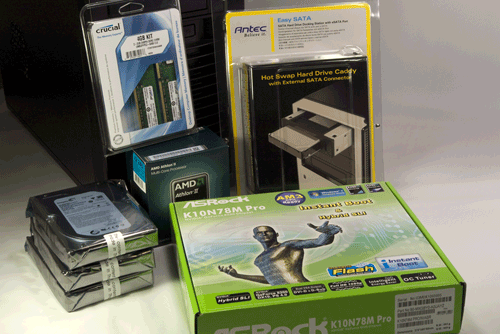
Figure 8-1. Home server components, awaiting construction
Make sure you have everything you need before you start building the system. Open each box and verify the contents against the packing list.
He Got Up, Got Dressed, and Took a Shower
As always, you needn't follow the exact sequence of steps we describe when you build your own home server. Always install the processor and memory before you install the motherboard in the case, because doing otherwise risks damaging the processor, memory, or motherboard. The exact sequence doesn't matter for most other steps, though. Some steps must be taken in the order we describe, because completing one step is required for completing the next, but as you build your system it will be obvious when sequence matters.
Preparing the Case
The first step in preparing any case that has an installed power supply is to look for an input-voltage selector switch on the rear of the power supply.
If that switch is present, make sure it's set to the correct input voltage. If the switch is set for 230VAC and you connect the system to a 115VAC receptacle, nothing bad happens. The power supply provides only half the voltage the motherboard and other components expect, and the system simply doesn't power up. However, if the input voltage is set to 115VAC and you connect the power supply to a 230VAC receptacle, the system will receive twice the voltage it's designed to accept, and you'll get a nice (and expensive) fireworks show.
The Antec TruePower Trio 550 power supply in the Atlas 550 is autosensing, which means it detects the input voltage and adjusts itself automatically. No switch necessary, and nothing to worry about. But if you're using some other case and power supply, make sure to check.
To begin preparing the Antec Atlas 550 case, place it upright on a flat surface. Loosen both of the captive thumbscrews that secure the side panel, as shown in Figure 8-2, and then swing the panel out and remove it from the case, as shown in Figure 8-3.
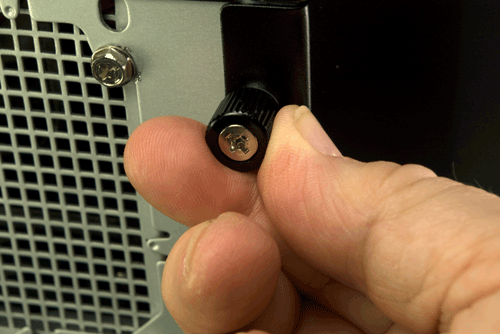
Figure 8-2. Loosen both captive thumbscrews on the rear of the left side panel
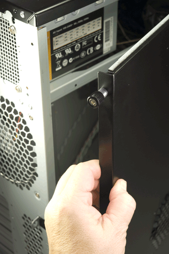
Figure 8-3. Swing the side panel out and remove it from the case
The front bezel is secured by three black plastic latching tabs at the left front edge of the chassis. Press the top tab gently to release the tension and pull outward very gently on the top of the front bezel to prevent that tab from snapping back into place. Repeat this procedure for the middle tab, as shown in Figure 8-4, and the tab located near the bottom of the chassis frame.
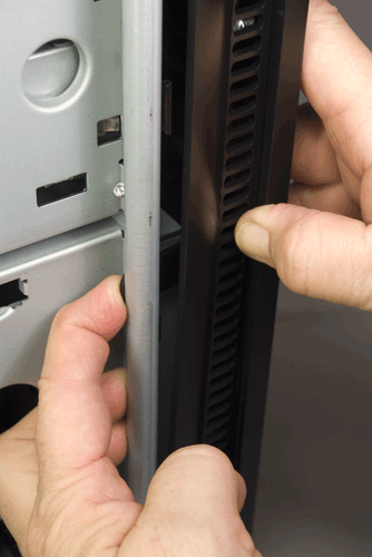
Figure 8-4. Release the three latching tabs that secure the front bezel to the chassis frame
After you release all three latching tabs, swing the front bezel out about 45°, as shown in Figure 8-5. Lift the front bezel straight up an inch or so, remove it, and place it aside.
With the front bezel removed, the hard drive cage cover, shown in Figure 8-5, is visible. Loosen the two thumbscrews, top and bottom, that secure the drive cage cover, as shown in Figure 8-6.
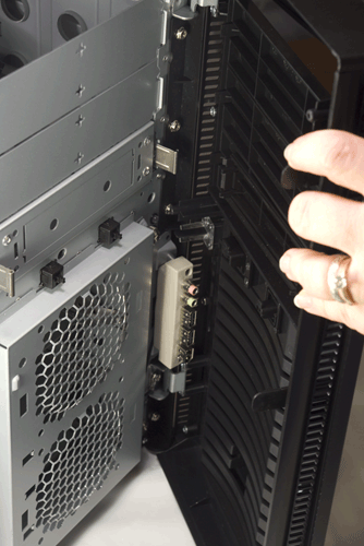
Figure 8-5. Swing the front bezel out to about 45°, lift it clear, and set it aside
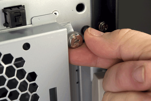
Figure 8-6. Loosen the two thumbscrews that secure the hard drive cage cover
Swing the drive cage cover open, as shown in Figure 8-7. Lift it straight up to remove it, as shown in Figure 8-8, and set it aside.
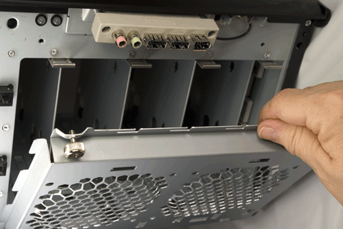
Figure 8-7. Swing the drive cage cover open
The drive cage contains four hard drive mounting trays, each of which is retained by a pair of spring-metal clips. Remove as many drive trays as you have hard drives to install by squeezing both clips and pulling the tray straight out of the chassis, as shown in Figure 8-9. Set the drive tray(s) aside for now.
For the best cooling, provide as much space as possible between the hard drives. If you're installing two hard drives, remove the top and bottom drive trays. If you're installing three hard drives, as we did, leave one of the middle two drive trays unused.
The plastic bag that contains screws and other components is located in one of the external drive bays at the top of the chassis. Use your dykes (diagonal cutters), as shown in Figure 8-10, to cut the plastic cable tie that secures the parts bag to the chassis. If you don't have dykes, carefully use a sharp knife or similar tool. Set the parts bag aside.
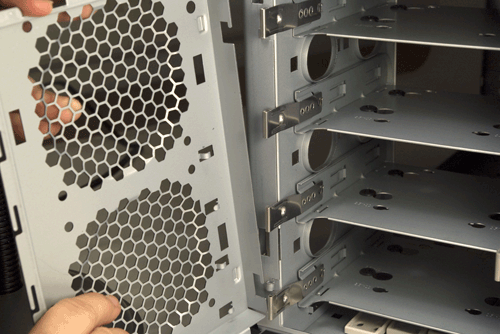
Figure 8-8. Lift the drive cage cover slightly to release it, and set it aside
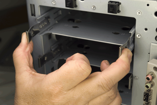
Figure 8-9. Remove drive trays by squeezing both metal clips and pulling the drive tray straight out of the chassis
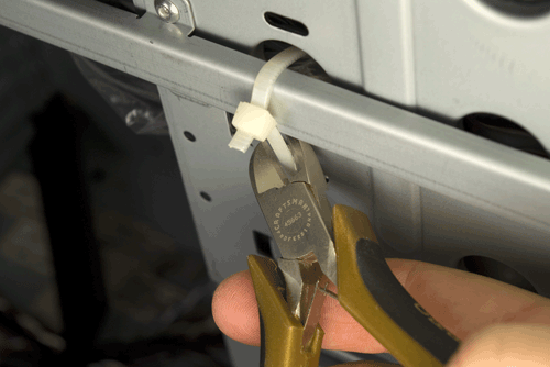
Figure 8-10. Cut the cable tie that secures the parts bag to the chassis
Installing the Hard Drive(s)
The next step is to install the hard drive(s). To begin, place the hard drive inverted (circuit board–side up) on a flat surface and position a drive tray on top of it, as shown in Figure 8-11. Make sure the drive and drive tray are oriented correctly, with the front of the hard drive on the side of the drive tray that has the metal clips. The rear of the hard drive, with the power and data connectors, should protrude from the rear of the tray, as shown in Figure 8-11.
Locate four of the special hard drive mounting screws in the parts bag. (One of these screws is shown at the bottom left of Figure 8-11.) Align the holes in the rubber grommets on the drive mounting tray with the screw holes in the bottom of the hard drive, and secure the hard drive by driving in the four screws. Tighten the screws finger-tight plus a quarter turn or so, but be careful not to overtighten them. Overtightening eliminates the noise- and vibration-damping benefits of the grommets. Repeat this procedure for each of your hard drives.
Flat Versus Phillips
Yes, we used a flat-blade screwdriver to secure the hard drives. The special hard-drive mounting screws Antec supplies have a combination straight/Phillips head, but the Phillips portion is so shallow that we were able to get a better grip with the flat-blade screwdriver.
Locate as many SATA data cables as you have hard drives. The SATA ports on your motherboard may be numbered starting with 0 or 1. (The ASRock motherboard we used uses both numbering methods.) Use a felt-tip pen to label each SATA data cable on both ends with the number of the drive/port you'll use it with, as shown in Figure 8-12. Label both sides of each cable to make sure the label will be visible after the cables are installed.
Connect a SATA data cable to each of your hard drives, as shown in Figure 8-13. The connector is keyed with an L-shaped socket and plug. Make sure the cable connector and drive connector are aligned properly and then press the cable connector straight in until it seats. Avoid placing any lateral pressure or torque on the connectors, which are relatively fragile. Install the other SATA data cables on the remaining hard drive(s), if any.
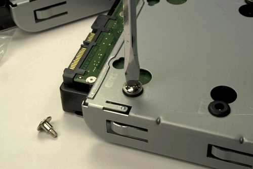
Figure 8-11. Place the hard drive inverted on a flat surface and use four of the special drive-mounting screws to secure it to the drive tray
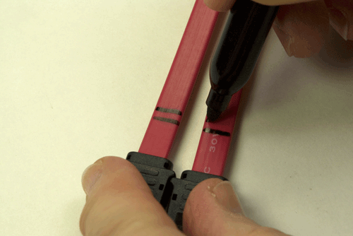
Figure 8-12. Label each of your SATA data cables with the drive/port number you'll use them with
Feed the free end of the SATA data cable through the drive bay and into the interior of the case. Align the drive tray with the chassis and slide the tray into the chassis, as shown in Figure 8-14. Press the drive tray until the spring clips snap into place, securing the hard drive. Repeat this procedure for each of the remaining hard drives, if any. When you've finished, check all of the SATA data cables to make sure they're still fully seated.
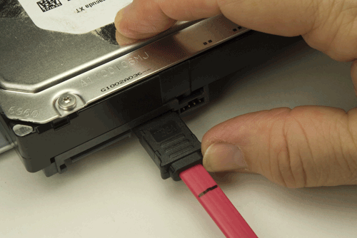
Figure 8-13. Connect a SATA data cable to the hard drive
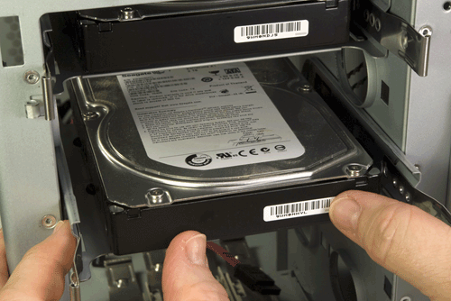
Figure 8-14. Slide the drive tray back into the chassis and press firmly until the spring clips snap into place
To reinstall the hard drive bay cover, align the pins on the left side of the drive bay cover with the sockets on the chassis, and lower the drive bay cover back into place, as shown in Figure 8-15. Swing the drive bay cover closed and tighten both thumbscrews to secure it, as shown in Figure 8-16.
Hard Drive Fans
If you want to install one or two 92 mm supplemental cooling fans for the hard drive bay, now is the time to do so. You can use any standard 92 mm case fan.
If you install one or both of these fans, make certain that they are oriented to push air into the case rather than draw air out of it. Look for an arrow on the body of the fan, which indicates the direction of the air flow.
To mount a fan, simply install the four mounting screws or expansion connectors supplied with the fan in the four holes surrounding the fan grill on the hard drive bay cover. Run the fan power cable into the interior of the case, and connect it to an available power connector.
If you install a fan or fans that have switchable speeds, decide how much noise you're willing to tolerate. If the server is in an area where noise is not an issue, set the fans to run on high. Otherwise, start by setting them on low and increase the speed later if you need more cooling.
Different fans have different power connectors. The most common is a standard Molex (old-style hard drive) power connector. If your power supply has one or more Molex connectors labeled Fan-Only, you can use those to allow the power supply to control fan speed. If you do that, set the fan power switch to high. If you set it to medium or low, the voltage supplied by the Fan-Only power connector may not be sufficient to spin up the fan. If your fan has a three- or four-pin header-pin connector, it's designed to be connected to the motherboard. Locate a header-pin connector on the motherboard labeled Aux Fan or Case Fan and connect the fan power cable to that set of header pins. Once again, if the fan has a speed switch, set it to high.
We decided not to install any hard drive fans in our server, at least initially. We'll keep an eye on hard drive temperatures, and install a fan or fans later if necessary.
Figure 8-15. Align the pins on the drive bay cover with the sockets in the chassis and lower the drive bay cover back into place
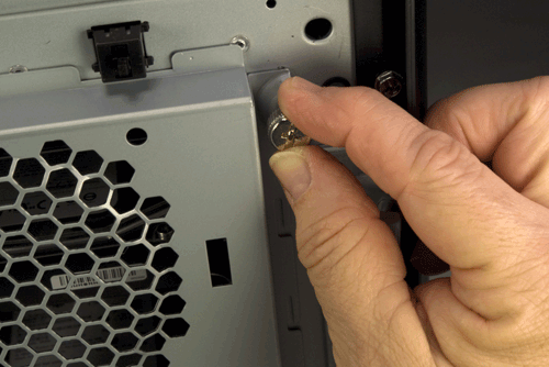
Figure 8-16. Reinsert the thumbscrews to secure the drive bay cover
Preparing the Motherboard
With the hard drives installed, the next step is to prepare the motherboard by installing the processor, CPU cooler, and memory. Some manuals suggest installing the motherboard in the chassis before installing the processor and memory, but after nearly cracking a motherboard by doing it that way, we decided it was much safer to install the processor and memory first.
To begin, locate the metal cam lever on the side of the processor socket. Press the cam lever slightly outward (away from the socket) to release it from the plastic latches that secure it, and then lift the lever, as shown in Figure 8-17.
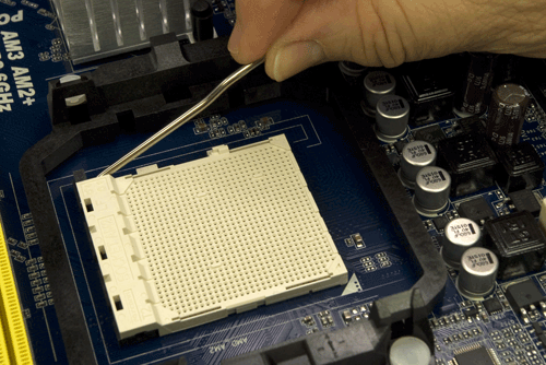
Figure 8-17. Release the cam lever from the processor socket and lift it up
Open the outer box of the processor and remove the hard plastic shell that contains the processor. Open that package carefully. Touch the chassis or power supply to ground yourself before you touch the processor itself. Remove the processor from the antistatic foam bed on which it rests. Align and orient the processor carefully with the processor socket. The socket and processor are keyed, with an arrow on one corner of the processor and a corresponding key on one corner of the processor socket.
When you have the processor and socket aligned, simply drop the processor into the socket, as shown in Figure 8-18. The processor should seat fully with no pressure whatsoever. Do not apply any pressure; doing so risks bending the fragile contact pins. If the processor doesn't drop into the socket freely, it's not aligned properly. Realign it and try again until it drops easily into the socket and seats completely.
Once the processor is seated properly, swing down the metal cam lever and snap it into place under the plastic locking tab on the socket, as shown in Figure 8-19. You should feel slight resistance on the cam lever as the cam clamps the socket onto the processor pins. If the resistance is anything more than slight, back up and start over.
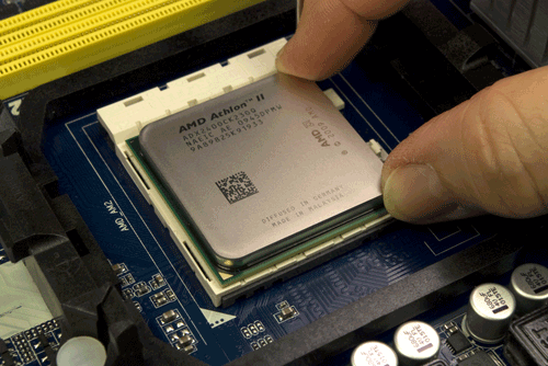
Figure 8-18. Orient and align the processor properly with the socket and then drop it into place
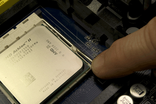
Figure 8-19. Press the cam lever down and snap it into place under the plastic locking tab on the processor socket
With the processor seated and clamped into place, the next step is to install the CPU cooler. Before you install the cooler, examine the bottom of the heatsink to verify that the patch of thermal compound is present and undamaged.
When Recycling Is Bad
If you ever remove and replace the processor, don't attempt to reuse the thermal compound. Rub off any compound present on the processor surface and the heatsink base—if it's tenacious, you can warm it slightly with a hair dryer—and then polish both the processor surface and the heatsink base with a clean paper towel to remove all traces of the old compound. Apply new thermal compound according to the instructions supplied with it. (We generally use Antec Silver thermal compound, which is inexpensive and effective.)
The CPU cooler mounts to the processor socket using two shiny metal latches on the CPU cooler that fit over two black plastic tabs on the processor socket. One of those latches is free-floating, and the other has a camming lever that allows the CPU cooler to be locked into place. The CPU cooler can be oriented so that either latch fits over either tab, but it's more convenient to use the free-floating latch toward the interior of the motherboard (where there is less clearance) and the cammed latch on the edge of the motherboard.
Examine the CPU cooler and locate the side with the free-floating latch. Tilt the opposite side of the CPU cooler up slightly, and hook the free-floating metal latch over the black plastic tab on the side of the processor socket near the passive heatsink, as shown in Figure 8-20.
Pivot the CPU cooler down and into full contact with the processor, making sure that the first latch remains connected. Maintaining finger pressure to keep the CPU cooler in position, press the second (cammed) latch into position over the second black plastic tab, as shown in Figure 8-21.
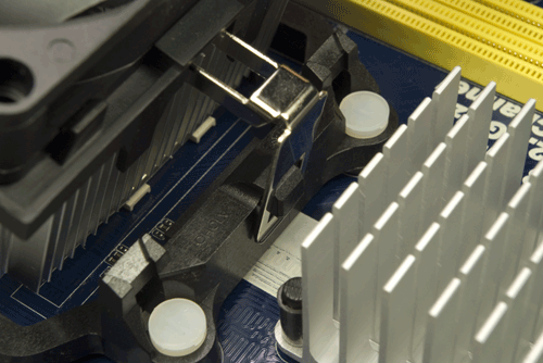
Figure 8-20. Hook the free-floating metal latch over the black plastic tab on the processor socket
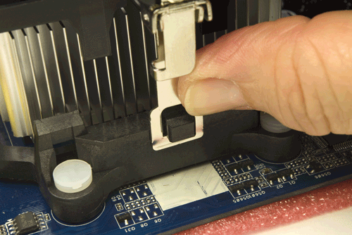
Figure 8-21. Press the cammed latch into position over the second tab
Verify that both latches are secured over both tabs, and then press the black plastic cam lever down until it latches to lock the CPU cooler to the processor socket, as shown in Figure 8-22.
Ordinarily, the next step would be to connect the CPU cooler fan power cable to the motherboard CPU fan header pins. In this case, though, the position of the CPU fan header pins made it more convenient to install the memory before we connected the CPU fan.
With the processor installed, the next step is to install the memory modules. To begin, swing open the DIMM locking tabs on both sides of both memory sockets, as shown in Figure 8-23.

Figure 8-22. Press the black plastic cam lever on the CPU cooler down until it latches to secure the CPU cooler to the processor socket
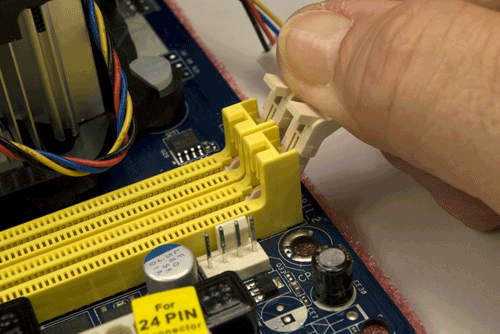
Figure 8-23. Open the DIMM locking tabs on both sides of both memory sockets
Before handling the memory modules, touch the chassis or power supply to ground yourself. Align the first DIMM with a memory socket, as shown in Figure 8-24. Make sure the keying notch on the contact edge of the memory module aligns with the keying tab in the socket and that the two sides of the memory module fit into the slots on the vertical sides of the memory slot.
Make sure that the memory module and slot are lined up properly, with the memory module vertical relative to the slot. Using one thumb on each side of the memory module, press straight down until the memory module snaps into place, as shown in Figure 8-25.
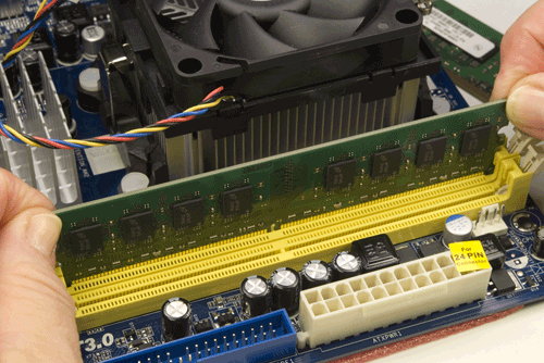
Figure 8-24. Align the memory module with the socket
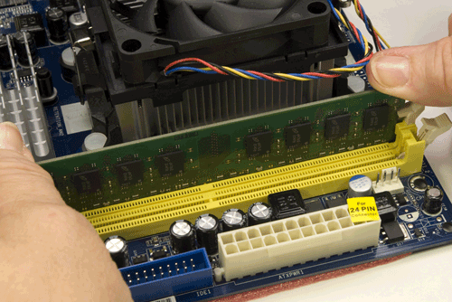
Figure 8-25. Press straight down on both sides of the memory module until it seats completely in the socket
After you seat the memory module, make sure the plastic latching tabs on the memory socket have snapped into place to latch the module into position, as shown in Figure 8-26. If the latching tabs are not seated in the notches on the memory module, it's possible that the module is not seated completely. The metal contacts on the base of the module should be concealed by the memory socket. If any are visible, the module is not fully seated.
Repeat this process with the additional memory module(s).
With the memory installed, you can now connect power to the CPU fan, as shown in Figure 8-27.
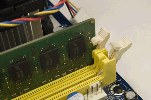
Figure 8-26. Verify that the memory module is latched into position
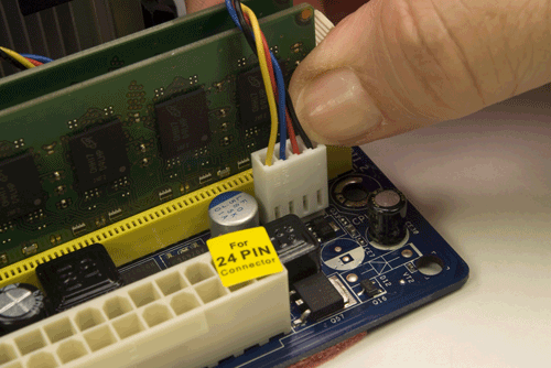
Figure 8-27. Connect the CPU fan power cable to the CPU fan header pins
The motherboard is now prepared. Place it aside for now. Use the antistatic foam under the motherboard to make sure it's not damaged by static electricity.
Final Case Preparation
Next, we'll complete a few final case-preparation steps to ready the case to receive the motherboard. To begin, remove the I/O shield installed in the Antec Atlas 550 case. The easiest way to do that is to press on the outside of the I/O shield with a tool handle, as shown in Figure 8-28, until the I/O shield pops loose. You can discard this I/O shield.
Locate the I/O shield in the motherboard box and hold it up to the rear I/O panel of the motherboard, as shown in Figure 8-29, to make sure that the holes in the I/O shield correspond to the ports on the motherboard rear I/O panel.
Working from inside the case, position the I/O shield and use a tool handle to press gently on it until it snaps into position, as shown in Figure 8-30. Be careful not to bend the thin metal of the I/O shield. If necessary, use your fingers on the outside of the I/O shield to support it while you're pressing it into position.
With the custom I/O shield installed, the next step is to determine the proper number and location of the motherboard mounting standoffs. The ASRock motherboard has six mounting holes. The Atlas 550 case comes with four brass standoffs installed, only two of which are in the proper positions for the motherboard. (The remaining two are located off to one side where they can't contact the motherboard; you can leave those standoffs installed or remove them, as you like.)
Locate the motherboard mounting hole positions by holding the motherboard up to a bright light. Slide the motherboard temporarily into position in the case to determine which of the holes in the chassis need to have standoffs installed. We used a felt-tip pen to mark the holes in the chassis that needed standoffs to be installed, as shown in Figure 8-31.
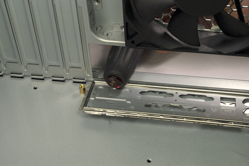
Figure 8-28. Use a tool handle to press on the outside of the I/O shield until it pops free
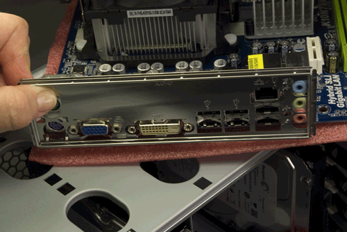
Figure 8-29. Verify that the custom I/O shield supplied with the motherboard in fact matches the rear I/O panel of the motherboard
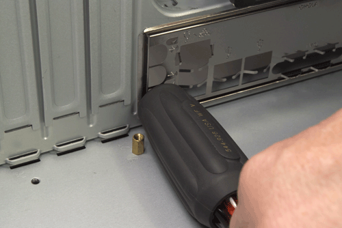
Figure 8-30. Position the I/O shield and press gently until it snaps into position
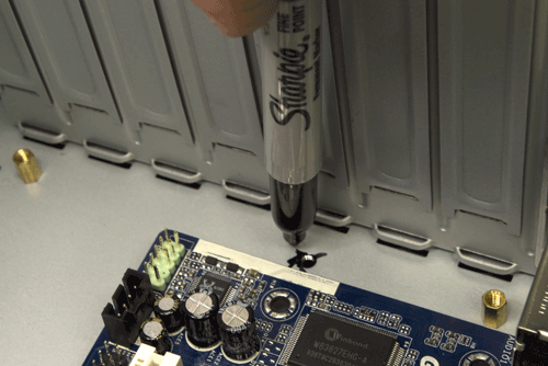
Figure 8-31. Mark the chassis holes that need standoffs to be installed
After you locate and mark the four additional mounting holes that require standoffs, hold the motherboard directly over the case and look straight down through each mounting hole in the motherboard to verify that you've marked the correct holes. Then locate the four additional standoffs in the parts bag and install them, as shown in Figure 8-32. You can use your fingers to install and tighten the standoffs, but we found it easier to use our 5 mm nut driver. Do not overtighten the standoffs, or you risk stripping the threads.
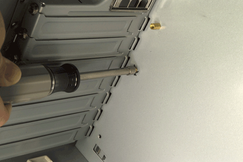
Figure 8-32. Install four additional standoffs in the marked mounting holes
Installing the Motherboard
Slide the motherboard into position. Before you begin driving in screws to secure the motherboard, examine the back panel carefully to make sure that none of the grounding tabs on the I/O shield intrude into the motherboard port connectors, as shown in Figure 8-33. A bright flashlight is helpful here.
When you're sure the motherboard is properly positioned relative to the I/O shield, install one screw through the motherboard and into a standoff, as shown in Figure 8-34. Tighten that screw only partially.
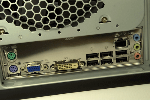
Figure 8-33. Verify that none of the grounding tabs on the I/O shield have fouled motherboard I/O port connectors
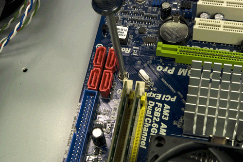
Figure 8-34. Drive screws through the motherboard mounting holes and into their corresponding standoffs
You'll need to apply some pressure against the springiness of the I/O shield to align the motherboard mounting holes with the standoffs. Get a second mounting hole aligned with its standoff and install a second screw. Once you've driven in the second screw, all of the mounting holes should align properly with their corresponding standoffs. Tighten all six motherboard mounting screws finger-tight, plus at most a quarter turn. Do not overtighten them, which risks cracking the motherboard.
Remove the cable tie that secures the bundle of cables from the power supply. Locate the ATX12V power cable, and route it to the ATX12V socket on the motherboard, located between the processor socket and the rear I/O panel. The ATX12V socket and plug are keyed. Orient the plug properly with the socket and press the connector into place, as shown in Figure 8-35.
Locate the 24-pin main ATX power cable in the power supply cable bundle, and route it to the front edge of the motherboard, just in front of the memory slots. The plug and jack are keyed. Orient the cable connector properly relative to the motherboard socket and press the cable connector into place, as shown in Figure 8-36. Make certain that the latch on the cable connector snaps into place over the tab on the motherboard connector to lock the cable into place.
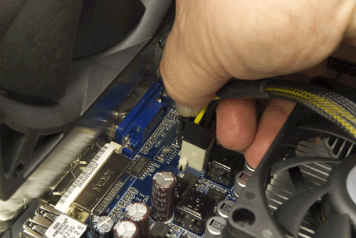
Figure 8-35. Connect the ATX12V power cable from the power supply to the motherboard
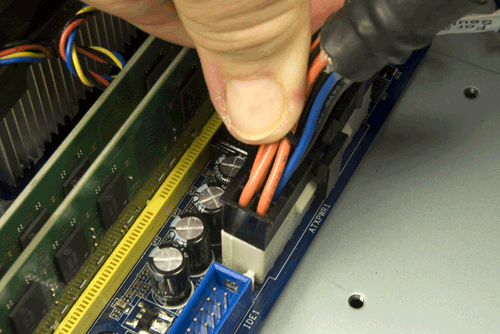
Figure 8-36. Connect the 24-pin main ATX power cable from the power supply to the motherboard
Connecting Front-Panel Ports and Indicators
With the case still on its side, it's now a good time to install the various front-panel connectors. To begin, locate the front-panel audio cable in the bundle of cables coiled up near the front of the case. This cable has two connectors, one for AC'97 audio and the other for HD audio. Locate the front-panel audio header-pin set in the back corner of the motherboard, which is keyed with a missing pin that corresponds to a blocked hole on the HD audio cable. Orient the HD audio cable connector properly relative to the header pins and press it onto those pins, as shown in Figure 8-37.
In addition to the six rear-panel USB ports, the ASRock motherboard includes two sets of USB header pins located near the front corner of the motherboard, each of which provides two USB ports. Locate the front-panel USB cable and route it to the USB header-pin set's location. Like the front-panel audio cable, the USB cable and motherboard connector are keyed with a missing pin and blocked hole. Orient the USB cable connector properly relative to the header-pin set, and press the connector onto the header pins, as shown in Figure 8-38.
The Atlas 550 also provides a front-panel IEEE1394 (FireWire) port, but our motherboard provides no connector for it. If your motherboard provides a set of FireWire header pins, connect that cable to those pins, but first verify that the pinouts on the cable connector and the header-pin set correspond properly. The motherboard manual and the case manual should both specify the pinouts used; if these do not match exactly, re-pin the cable connector using the instructions provided in the case manual.
![]() Frying Peripherals
Frying Peripherals
Years ago, we found out the hard way that just because a front-panel IEEE1394 cable connector fits an IEEE1394 header-pin set doesn't mean the connection is wired properly. We connected a camcorder to a miswired front-panel IEEE1394 port and promptly blew the circuitry on the camcorder. That was an expensive lesson, but one we'll never make again.
With all of the front-panel ports connected, it's time to connect the front-panel switch and LED indicator cables. The two-pin switch connectors—the power switch and reset switch—are not polarized. They can be connected either way and will still work. Connect the reset switch and power switch by pressing their connectors onto the proper pairs of header pins, as shown in Figure 8-39.
LED connectors are polarized. If you connect one backward, the LED won't illuminate, but no damage is done. By convention, ground on these two pin connectors is the side with the white or black wire, and positive (+) is the side with a colored wire. Most motherboards have the proper polarity silkscreened onto the board near the connection, but this ASRock motherboard does not. Fortunately, the only LED cable we need to connect is the hard drive activity indicator, visible in Figure 8-39 behind and to the right of the POWER SW connector. That connector is oriented properly in the image, with the red wire toward the USB connector to its right.
![]() We Hate It When That Happens...
We Hate It When That Happens...
The power LED connector on the ASRock motherboard is two adjacent header pins. The Atlas 550 Power LED cable also uses two pins, but on a three-pin connector, with the middle position empty. This sort of mismatch is pretty common, particularly with the power LED and speaker connectors.
Unfortunately, there's no convenient way to solve the problem, unless the motherboard provides both sorts of connector (some do, but not this one). We actually decided to leave the power LED unconnected, because our server will sit under Robert's desk, where the power LED wouldn't be visible anyway.
If you want your power LED to work, you'll have to do some minor surgery. Use your dykes or a sharp knife to cut the three-pin power LED cable connector in half, leaving you with each of the two wires on separate connectors, and then connect those two wires individually to the appropriate motherboard header pins.
With all of the front-panel cables connected, the next step is to connect the SATA data cables to the motherboard SATA ports. The ASRock motherboard provides four SATA ports, labeled SATAII_1 (Port 0) through SATAII_4 (Port 3). We have three hard drives to connect, and it doesn't really matter which drive we connect to which port. But we like to be as organized as possible, so by habit we connect the first hard drive to Port 0, the second to Port 1, and so on. To connect a SATA data cable, verify that the L-shaped key in the cable connector is oriented properly relative to the key in the motherboard SATA port, slide the connector into the port body, and press straight down until the connector fully seats, as shown in Figure 8-40. After you connect the hard drives, verify that all of the SATA data cables are securely seated on both ends.
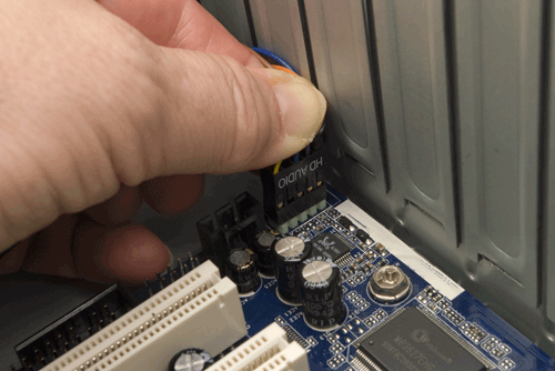
Figure 8-37. Connect the front-panel HD audio cable to the HD audio header pin set
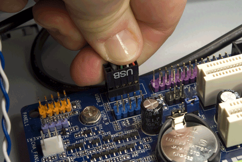
Figure 8-38. Connect the front-panel USB cable to the USB header-pin set
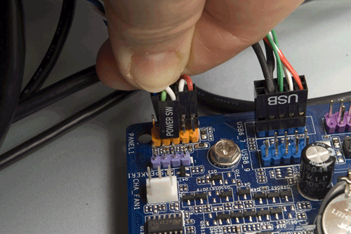
Figure 8-39. Connect the front-panel switch and indicator cables
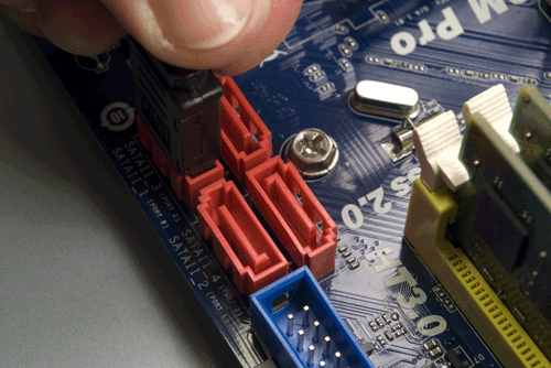
Figure 8-40. Connect the SATA data cables to the motherboard SATA ports
With three hard drives installed, our configuration leaves one of the motherboard SATA ports free. We'll actually leave that port unused for now, but we may use it later to add a fourth hard drive. Depending on your hard drive configuration, you may have one or more ports free. You can use one of those for an optical drive or for the Antec Easy SATA hard drive docking station, which we'll talk about shortly.
Connecting Power to the Hard Drives and Fan
With the SATA data cables connected, it's time to connect power to the hard drives and case fan. Lest we forget, let's get the case fan connected first. In the bundle of cables coming from the power supply, locate the connector labeled FAN ONLY. Connect that cable to the power cable from the rear case fan, as shown in Figure 8-41. If you installed one or two 92 mm supplemental fans to cool the hard drive cage and didn't connect power to them at the time, connect them now as well.
The next step is to connect power to the hard drives. It pays to do a little bit of planning here, both to make sure you can dress all the cables neatly after you finish assembling the system and to make sure your SATA power cables can reach all of your SATA devices. If you're using only hard drives in your server, and if they're all located in the lower 3.5" hard drive cage, you won't have any problem. If you're installing SATA devices in the top (5.25") drive bays, getting power to all the SATA devices may be a stretch, literally.
To connect a SATA power cable to a drive, first ensure that the L-shaped key on the power cable and the corresponding key on the drive connector are oriented properly. Then slide the SATA power cable connector onto the drive power connector and press until it seats, as shown in Figure 8-42.
![]() Fried Drives
Fried Drives
Large hard drives aren't cheap. Although we connected the data and power cables to all three of the 2 TB drives in the sequence we describe here, we did that only to preroute the cables, to make it easier to dress them.
Before we powered up the system for the first time (the "smoke test"), we disconnected the power and data cables from all three of the 2 TB drives and temporarily connected an old 160 GB SATA drive. That way, if the power supply or motherboard turned out to be catastrophically defective, we'd fry only the old, small hard drive. Once we were satisfied that the system worked normally, we shut it down and reconnected the three real system hard drives.
In all of the systems we've built over the last 20 years, we've had only one catastrophic smoke test. That was enough to teach us caution. If you don't have an expendable spare hard drive, you can do the first boot with no drives connected or connect just an optical drive.
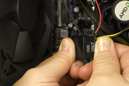
Figure 8-41. Connect the case fan to a FAN ONLY power connector
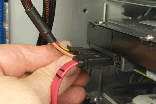
Figure 8-42. Connect a SATA power cable to each of the hard drives
Installing an Optical Drive and/or Hard Drive Docking Station
At this point, we're nearly finished building the system. All that remains to be done is installing the optical drive or hard drive docking station—temporarily, in our case, but perhaps permanently in yours—and completing a few other final tasks.
Until now, we've been working with the case on its side. It's easier to install drives in the 5.25" drive bays if the case is sitting normally, so stand it up on your work surface. If you don't intend to leave an optical drive installed permanently, there's no point to installing it in the case. Instead, just set it on top of the case, as shown in Figure 8-43, and temporarily connect the SATA data and power cables to it.
Note the Antec Atlas 550 pamphlet between the optical drive and the Atlas 550 case. Although an optical drive is unlikely to short out even with the bottom of the drive in direct contact with the metal chassis frame, after once shorting out a hard drive we've gotten in the habit of using insulating material between the drive and the metal case.
If you're installing an optical drive permanently, locate two drive rails and the parts bag with the mounting screws. Position one drive rail as shown in Figure 8-44. With the drive rail in this position, the optical drive will protrude just far enough out of the chassis that its bezel is flush with the front case bezel.
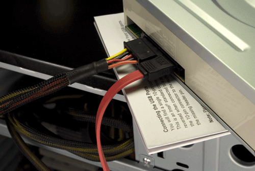
Figure 8-43. An optical drive connected temporarily
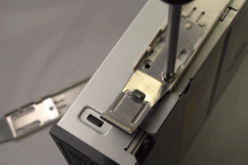
Figure 8-44. Install drive rails on both sides of the optical drive
There are four screw holes in the mounting rail and the drive, but we've never found it necessary to use more than two screws per drive rail, one at the bottom front and one at the top rear. Locate four drive mounting screws, and test one to make sure it matches the screw holes in the drive. Once you're sure you have the correct screws, secure both rails to the drive, using two screws for each. Connect a SATA data cable to the drive, feed that cable through the drive bay into the case, and then slide the optical drive into the case, as shown in Figure 8-45. Use both thumbs to press the drive into position until you hear the spring-metal tabs latch into place. Working from inside the case, connect a SATA power cable to the power connector on the rear of the drive.
If you're installing an Antec Easy SATA hard drive docking station instead of or in addition to the DVD writer, the procedure is the same: attach drive rails to both sides of the Easy SATA frame, slide the frame into the chassis, as shown in Figure 8-46, and connect SATA data and power cables.
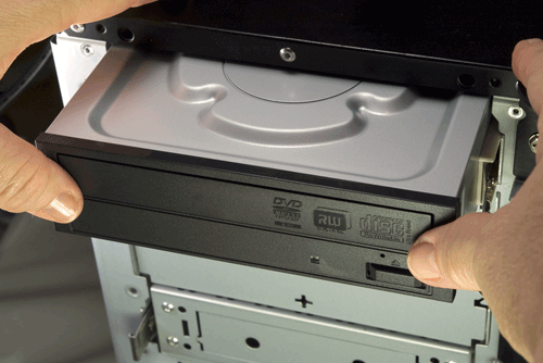
Figure 8-45. Slide the drive into the chassis and press until it latches
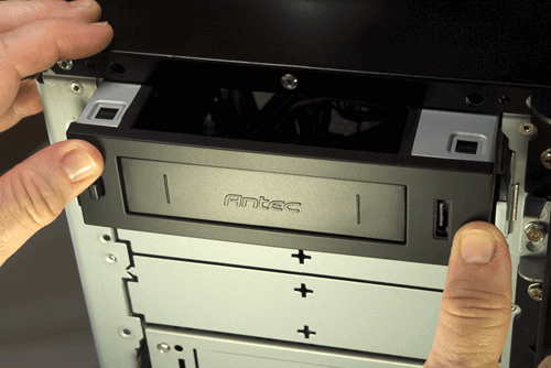
Figure 8-46. Installing an Antec Easy SATA hard drive docking station
The Easy SATA docking station also provides an eSATA connector, visible in Figure 8-46 just to the left of Barbara's right thumb. If your motherboard has a spare SATA port and you want to make this eSATA port live, connect the captive cable inside the Easy SATA unit to that free SATA port. Note that this connector provides only SATA data, not power, so any external drive you connect to it must be powered separately.
Configuring and Using the Antec Easy SATA
To enable hot-swapping, the Antec Easy SATA docking station requires Advanced Host Controller Interface (AHCI) support. Before you install the operating system, enter BIOS Setup and locate the SATA configuration screen. If SATA is already set to use AHCI, you need make no changes. If SATA is set to IDE, change the setting to AHCI, save your settings, exit BIOS Setup, and restart the system.
If Windows Vista or Windows 7 is already installed, changing the SATA setting from IDE to AHCI will render the system unbootable, so exit BIOS Setup without making any changes. Visit http://support.microsoft.com/kb/922976 and follow the instructions there to enable AHCI on your system. If you have a recent Linux version installed, use your package manager to verify that the AHCI driver is installed, use BIOS Setup to enable AHCI, save the settings, and restart the system.
To install a hard drive in the Antec Easy SATA hard drive docking station, press the button on the left front of the docking station to release the latch, and slide the drive—with the circuit board side down and the SATA connectors facing the case—into the bay until you feel it seat. (When fully seated, the front of the drive protrudes from the Easy SATA bay, which allows you to grip the drive to remove it.)
As soon as the drive connectors make contact, the drive should spin up. After a few seconds, as it reaches operating speed, a drive icon will appear automatically under Windows or Linux. (The drive icon may not appear automatically under Windows 7; if it doesn't, refresh [F5] your drives list and it should appear.) At that point, you can read from and write to the drive just as you would any internal hard drive.
To remove the drive, ensure that it is not in use and that all cached data has been flushed to the drive. (Right-click on the drive icon and choose "Remove Drive Safely," "Unmount," or a similarly worded option.) Press the button on the front of the Easy SATA bay to unlock the drive and then pull the drive far enough out of the bay to break the power connection. Allow several seconds for the drive to spin down and the heads to lock, and then pull the drive completely out of the bay. (If you simply pull the drive straight out of the bay without allowing it to spin down, the spinning platters act as a gyroscopic stabilizer, which is disconcerting. The first time we did that, we nearly dropped the drive.)
Finishing Up
At this point, the new system is just about ready to roll. Before you power it up, though, take a few minutes to do a few final tweaks.
First, if your server looks anything like ours did, there's a rats' nest of cables running hither and yon. Your new system will look better, be easier to troubleshoot, and be more reliable if you dress those cables and tuck them out of the way. To dress the cables, organize them into bundles and route them as far away from the motherboard and other components—particularly fans—as possible. If necessary, disconnect cables temporarily to untangle them and reroute them as necessary. Use the cable ties supplied with the case to secure the bundles, and don't hesitate to tuck the cables under or tie them to chassis components to get them out of the way. (If you need more cable ties, the yellow plastic ties supplied with lawn bags work well.)
After you finish dressing the cables, do a final check to make sure everything is correct:
☐ Power supply input voltage set correctly (if applicable)
☐ No loose tools or screws (shake the case gently)
☐ CPU cooler properly mounted; CPU fan connected
☐ Memory modules fully seated and latched
☐ Front-panel switch and indicator cables connected properly
☐ Front-panel I/O cables connected properly
☐ Hard drive data cables connected to drives and motherboard
☐ Hard drive power cables connected
☐ Optical drive data cable connected to drive and motherboard
☐ Optical drive power cable connected
☐ All drives secured to drive bay or chassis, as applicable
☐ Expansion card(s) (if any) fully seated and secured to chassis
☐ Main ATX power cable and ATX12V power cable connected
☐ Case fan(s) installed and connected
☐ No unused cables flopping around
Once you're certain that all is as it should be, it's time for the smoke test. (As we mentioned earlier, you may want to do the smoke test with a minimal configuration to avoid risking all of your expensive hard drives.) Connect a keyboard, mouse, and display, and turn on the display.
Connect the power cable to the wall receptacle and then to the system unit. The Antec power supply has a separate rocker switch on the back that controls power to the power supply. By default, it's in the "0," or off, position, which means the power supply is not receiving power from the wall receptacle. Move that switch to the "1," or on, position. Press the main power button on the front of the case, and the system should start up. Check to make sure that all fans are spinning. You should also hear the hard drive(s) spin up. At that point, everything should be working properly.
False Starts
When you turn on the rear power switch, the system will come to life momentarily and then die. That's perfectly normal behavior. When the power supply receives power, it begins to start up. It quickly notices that the motherboard hasn't told it to start, though, so it shuts down again. All you need to do is press the front-panel power switch and the system will start normally.
If you did the smoke test with a minimal configuration, turn off the system now and reconnect the hard drives and any other components you'd left disconnected. After verifying that all connections are correct, turn the system back on and wait for the POST screen to display. Press F2 to enter BIOS Setup.
In BIOS Setup, verify that all of your devices are detected, including the full amount of memory, and set the correct date and time. Refer to your operating system documentation to determine if any other changes are necessary in BIOS Setup. Make any required changes, save those changes, and restart the system. At this point, you're ready to install your operating system and applications.
Final Words
This system went together smoothly and worked perfectly when we turned it on. Server hardware is useless without the software to run it, though, so we spent some time looking at various alternatives.
Choosing the operating system for a home server involves several trade-offs. We considered the following operating systems for our own home server:
Microsoft Windows Home Server
Originally available only from hardware OEMs bundled with server hardware, Windows Home Server (WHS) can now be purchased separately for about $100. Early releases of WHS had an impressive feature set—not surprising, considering that WHS is essentially a cut-down version of Windows Server 2003 SP2—but suffered some serious problems, notably a severe data corruption bug that went unpatched for far too long. The current V1 release supports Windows 7 clients and is reliable.
Microsoft plans to release WHS V2, a major upgrade, sometime in 2010. WHS V2 is based on Windows Server 2008 and requires a 64-bit processor, which obviously rules out upgrades for those running 32-bit systems. The WHS V2 feature set has not been announced as we write this, but we expect WHS V2 to include several major new features as well as significant upgrades to existing features.
We ruled out WHS for our server because it would make no sense to buy and install the dated WHS V1 with WHS V2 so close to release. If WHS V2 includes features we want—and they are worth the (presumably) $100 price tag—it will be easy enough to buy and install it later. For now, we can do what we need to do (and do it well) using free software.
Desktop Windows
We have numerous unused licenses lying around for versions of desktop Windows from Windows 7 all the way back to Windows NT 4. (Somehow we missed out on Vista.) We considered installing one of these—probably Windows XP—on our home server and simply setting up workgroup shares on the server. The problem with doing that is that desktop Windows is not designed to run headless, so we'd have to leave a display, keyboard, and mouse connected to the server. We have plenty of spares lying around, but leaving those peripherals connected would make it difficult to tuck the server away under Robert's desk as we planned.
Ubuntu Server
Ubuntu Server is free-as-in-beer and free-as-in-speech. It uses text-based installation and maintenance, so it's unlikely to be suitable for anyone who's not comfortable with command-line Linux. On the other hand, this is serious server software. It's stripped down to essentials, hence the absence of a default GUI, and it's far faster than any of the other products we considered. One wonderful feature of Ubuntu Server is its scripted setup of a LAMP (Linux, Apache, MySQL, PHP/Perl/Python) server. Setting up a LAMP server manually may take a newbie hours (or an experienced Linux administrator maybe 20 minutes). With Ubuntu Server, setting up a LAMP server is a single menu option. Frankly, we think Ubuntu Server is a pretty good choice for a small office server, provided you're already a moderately experienced command-line-savvy Linux administrator (or have access to a Linux guru for advice and assistance). But it really is overkill for most home servers, which typically don't need to run web servers, mail servers, and so on.
A desktop Linux distribution
If your functional requirements are modest, don't rule out using a standard desktop Linux distribution like Ubuntu on your server. In theory, there are a lot of disadvantages to doing that, but in practice many of those objections disappear. For example, a desktop Linux distribution is usually slower than a purpose-built server distribution. So what? We'll never notice any tiny performance difference that may exist. A desktop distribution may not support software RAID. Again, we don't care, because we plan to run a JBOD on our home server. Desktop Linux distributions also have advantages relative to server distributions. The biggest advantage for most people is that the desktop distro uses a familiar graphic interface. Setting up a shared disk volume or printer is usually a matter of a few clicks. And most desktop Linux distributions are set up to allow remote management by default, or can easily be configured to do so.
A NAS package
There are several Linux- or FreeBSD-based network-attached storage (NAS) distributions that are optimized to function as servers rather than workstations. They do nothing that any other Linux or FreeBSD distribution can't do, but the advantage is that they're preconfigured to provide NAS functions with a standard installation. You could spend hours or days getting a desktop Linux or FreeBSD distribution set up to do the same things.
Among the most popular of these NAS packages are FreeNAS (http://freenas.org), NASLite (http://www.serverelements.com), and TurnKey Linux (http://www.turnkeylinux.org). All run on standard x86 systems and can be configured and managed from a web browser running on a network client. We also looked at NexentaStor (http://www.nexenta.org), which is an industrial-strength NAS environment based on OpenSolaris. The main Nexenta product is commercial, but the community edition NexentaStor is freely downloadable and has only minor restrictions. (For example, the free version is limited to 12 TB of disk space in use.)
We looked at all of these alternatives except Windows Home Server, which we didn't have and didn't want to buy (for the reasons cited). We suggest you do the same before you decide on the OS for your server.
We first ruled out Windows Home Server, desktop Windows, and Ubuntu Server, for the reasons listed above. That left us with either desktop Linux or one of the NAS environments. We looked at several of the latter and decided that, as nice as some of them are, they really didn't do anything we needed to do that we couldn't do ourselves about as easily with a general Linux distro.
We ended up installing Ubuntu 10.04, mainly because it was familiar to us and we already knew how to do everything we needed to do to configure it as a remotely managed server. We run Ubuntu on all of our other computers, so using it on the server has the advantage of not requiring us to learn the ins and outs of a different operating system or distribution. Also, Ubuntu 10.04 is a long-term support (LTS) release, so we won't have to upgrade the OS until the next LTS release, 12.04, due in April 2012.
Alas, the best-laid plans sometimes go awry. Nothing we tried, including manually editing the xorg.conf file, allowed headless booting to work under Ubuntu 10.04. After beating our heads against the wall for several hours, we finally decided to punt. We installed Ubuntu 9.10, which worked perfectly.
Setting up headless booting, file sharing, and remote management in Ubuntu 9.10 took us all of 15 minutes, most of which we spent installing and configuring the Samba server, creating home directories and accounts, and setting permissions. When we finished setting up the server, we shut it down and disconnected the display, keyboard, and mouse. We then removed the optical drive, reinstalled the cover, moved the system under Robert's desk, connected it to the UPS and Ethernet, and pushed the start button. The system came up as expected and was visible to our network clients.
So we now have a stable server with gobs of disk space, which, after all, is what we set out to build.