4. Building a Mainstream System
A mainstream system is one that seeks balance at a reasonable price point. A mainstream system uses top-quality (but midrange in terms of performance) components throughout, because that is where you find the best value for your dollar. What differentiates a mainstream system from a budget PC is that the former makes fewer compromises. Whereas price is always a very high priority for a budget PC, it is less important for a mainstream system. If spending more money yields better performance or reliability, or adds desirable features, a mainstream system gets those extra dollars, whereas a budget PC probably doesn’t.
Relative to the budget PC, the mainstream system gets more expensive components, particularly where they pay off in additional performance, convenience, or data safety. Typically, it will have a better motherboard, a faster processor, more memory, more disk storage, better external peripherals, and additional features. Considered individually, the incremental cost of better components is usually quite small. But taken collectively, the difference adds up fast. Depending on which components you choose, a mainstream system may cost 50% to 100% more than a budget system. That extra money buys you higher performance now and later, and extends the period between upgrades. If a budget PC will meet your needs for 12 to 18 months without upgrades, a mainstream system may suffice for 24 to 36 months or longer, depending on the demands you put on it.
In this chapter, we’ll design and build the perfect mainstream system.
A Sheep in Wolf’s Clothing
Many consumer-grade systems, particularly those sold in office superstores and big-box stores and by some large OEMs, masquerade as mainstream systems but are really budget PCs with a few extra bells and whistles. These PCs have faster CPUs, more memory, and larger hard drives—components whose specifications are easily visible—but use the same low-end motherboards, cheap cases, and marginal power supplies found in their less expensive budget lines.
And the “upgrades” those systems include are often less significant than you might expect from the description. For example, that larger hard drive may be available in two models, one with an 8 MB buffer and the other with a 32 MB buffer. The latter model may cost $8 more. Guess which model you’ll find in that consumer-grade system? Or a system may be advertised as having a RADEON HD 5570 video adapter. What isn’t advertised is that that adapter uses slower memory and runs at a lower clock speed than the retail-boxed model you can buy.
True mainstream systems, at least as we define them, are a vanishing breed. Marketers believe that spending $5 more on a better power supply or $10 more on a better motherboard will only boost the price of their systems, making them uncompetitive with other brands, without increasing sales volume or profit. From their point of view, buyers are too ignorant to appreciate the difference between cheap components and good components that cost only slightly more. Unfortunately, they’re usually right. Of course, the best answer to that is to build your own mainstream system from top-notch components.
Determining Functional Requirements
First, we sat down to think through our own requirements for a mainstream system. Here’s the list of functional requirements we came up with:
Reliability
First and foremost, the mainstream system must be reliable. We expect it to run it all day, every day, for years, without complaint. The key to reliability is choosing top-quality components: particularly the motherboard, memory, hard drive, and power supply. These components don’t need to be the largest or fastest available, but they do need to be of high quality.
Balanced performance
A mainstream system is a jack of all trades and master of none. We expect it to perform any task we might give it at least competently, if not better. But, because this is not a cost-no-object system, we need to balance component performance against price. For example, we expect this system to be capable of serious number crunching, but the fastest processors cost more than we can justify for this system. Accordingly, we’ll aim for a balanced design that allows the system to do most things very well and everything else at least acceptably well.
Noise level
Most mainstream systems are used in environments where noise is an issue. Accordingly, we’ll design this system for quiet operation, but we won’t spend much extra money to do so. That means, for example, that we’ll choose the hard drive, case, and power supply based on noise level, but we won’t spend $50 extra to replace the stock CPU cooling fan with a silent unit or $100 extra for a fanless power supply. Our goal is a quiet PC, not a silent PC (if there can truly be such a thing).
Hardware Design Criteria
With the functional requirements determined, the next step was to establish design criteria for the mainstream system hardware. Here are the relative priorities we assigned for our mainstream system. Your priorities may, of course, differ.
|
Price |
★★★✩✩ |
|
Reliability |
★★★★✩ |
|
Size |
★★★✩✩ |
|
Noise level |
★★★★✩ |
|
Expandability |
★★✩✩✩ |
|
Processor performance |
★★★✩✩ |
|
Video performance |
★★✩✩✩ |
|
Disk capacity/performance |
★★★✩✩ |
As you can see, this is a well-balanced system. Other than expandability and video performance, which are relatively unimportant, all of the other criteria are of similar priority. Here’s the breakdown:
Price
Price is moderately important for this system, but value is more so. We won’t attempt to match the low price of commercial systems built with low-end components, but we won’t waste money, either. If spending a bit more noticeably improves performance, reliability, or usability, or if it adds features we want, we won’t begrudge the extra cost.
Reliability
Reliability is very important. A mainstream system that is not built for reliability is not worth building. We’ll also allocate some of the budget to a top-notch UPS to protect the system from power glitches and outright failures.
Size
Size is important because this system must fit in Barbara’s already crowded office, so we don’t want the system to be any larger than it needs to be to do its job. So, although we will not compromise other criteria in exchange for smaller size, we will choose the smallest case that meets other system requirements.
Noise level
Noise level is at least moderately important for nearly any mainstream system, and is very important for this particular mainstream system. Our goal is to build a quiet PC at little or no incremental cost rather than to build a “silent” PC using expensive special components. Accordingly, when we choose components we’ll keep noise level in mind, but we won’t pay much extra for a marginally quieter component. We’ll choose the quietest possible standard case and power supply, use large, slow-moving fans, use silicone-grommet hard drive mounts, and so on.
Expandability
Expandability is relatively unimportant for most mainstream systems, including this one. Fewer than 5% of commercial mainstream systems are ever upgraded, and those upgrades are usually of a minor nature, such as adding memory or replacing a video card or hard drive. Self-built mainstream systems are more likely to be upgraded, but even with these the upgrades are unlikely to require more than perhaps a spare drive bay or two, an expansion slot, or a couple of available memory sockets. We’ll choose a case, power supply, and motherboard that are adequate to support such minor upgrades.
Processor performance
Processor performance is important for a mainstream system, both initially and to ensure that the system can run new software versions without requiring a processor upgrade. Mainstream dual- and quad-core processors—which is to say $150 to $175 Intel Core i5 models and AMD Phenom II X4 models—are the “sweet spot” in price/performance ratio, so that’s what we’ll use. These will give us roughly twice the performance of a budget system, but without getting into the performance price range.
Video performance
3D graphics performance is important for a mainstream system only if you intend to use it to run 3D games. Otherwise, integrated video suffices. In particular, current-generation integrated video is good enough even for casual gaming. 2D video quality is important for any mainstream system, because it determines display clarity and sharpness for browsers, office suites, and similar 2D applications. AMD and Intel integrated video both provide excellent 2D quality and reasonably good 3D performance. To future-proof the system, we’ll choose a motherboard that provides a PCI Express x16 video card slot. That way, we can always add an inexpensive or midrange video adapter if we need better 3D performance or other features not supported by the integrated video.
Disk capacity/performance
Even though it will connect to a network that has several terabytes of available storage, disk capacity and performance are relatively important for this system because Barbara prefers to work locally, using network drives only for backing up. Fortunately, with fast 1 TB and larger hard drives currently selling for $100 or less, it’s easy and inexpensive to accommodate any reasonable disk storage requirements. We’ll start by installing a 1 TB drive, with the intention of adding drives from time to time as necessary to extend the life of the system.
Component Considerations
With our design criteria in mind, we set out to choose the best components for the mainstream system. The following sections describe the components we chose, and why we chose them.
![]() Your Mileage May Vary
Your Mileage May Vary
Although we tested the configuration we used to build our own mainstream system, we did not test permutations with the listed alternatives. Those alternatives are simply the components we would have chosen had our requirements been different. That said, we know of no reason the alternatives we list should not work perfectly.
Case and Power Supply
Antec Mini P180 μATX case (http://www.antec.com)
With a mainstream budget, we can afford a nice case and a premium power supply. There are literally scores of mainstream cases available, so it might seem that choosing just one would be an overwhelming task. As it turned out, though, we were able to narrow down the choices dramatically based on some non-negotiable spousal requirements. This mainstream system would become Barbara’s new main office system, and she had some very firm ideas about what constituted an acceptable case.
First and foremost, Barbara’s office is directly across the hall from the master bedroom. She has very sharp hearing and is a light sleeper, so even slight computer noise coming from the next room can keep her awake. We decided to consider only cases that incorporated Quiet PC technology, such as silicone-grommet hard drive mounts, sound-deadening panels, large (and quiet) cooling fans, and so on.
The available space limited us to a mini-tower μATX case, which narrowed the selection significantly. Because the system will reside under her desk, Barbara insisted on front-panel USB (for her MP3 players), audio (for her headphones and headset), and eSATA (for her external hard drives) ports. Nearly all mainstream cases provide front-panel USB and audio ports, of course, but relatively few provide a front-panel eSATA port. Although we’ll install only a DVD writer initially, Barbara wanted at least two 5.25” external drive bays because she may later decide to install a Blu-ray BD-ROM drive. Finally, Barbara specified one subjective requirement: this system will reside in her office, and she insisted that it be attractive.
Taken together, the objective requirements narrowed the field from hundreds of cases to a handful. Applying Barbara’s subjective attractiveness requirement narrowed the candidates to only one case, the Antec Mini P180.
The Mini P180 ships sans power supply, which means we can install any power supply that fits our needs and budget. We wanted a reliable, high-quality power supply rated at 450W to 550W, with high energy efficiency, active power-factor correction, and low noise. We’d budgeted $65 to $85 for the power supply. We found several units that met those requirements, including the Antec EarthWatts EA-500D Green, the Corsair CMPSU-450VX and CMPSU-550VX, and the Seasonic SS-500ET. Any of those models would be an excellent choice, but our familiarity and comfort level with Antec power supplies led us to choose the Antec EarthWatts EA-500D Green.
Motherboard
Intel DH55TC (http://www.intel.com)
Intel motherboards set the standards by which we judge all other motherboards for construction quality, stability, and reliability. For our mainstream system, we chose the rock-solid Intel DH55TC, which is a Socket LGA 1156 board that’s based on Intel’s mainstream H55 chipset. In fact, we liked this board so much that we ended up also using it for our media center system. (As Barbara commented, you know you’re a True Geek when you have a list of favorite motherboards.)
It’s not that the DH55TC has more features or better performance than its competition. In this class of motherboards, feature sets are similar and performance differences from board to board are too small to matter. It’s that the DH55TC Just Works. For example, unlike some competing boards, the DH55TC works flawlessly with the integrated video that actually resides on the Core i5 processor. And although an attractive motherboard isn’t necessarily a good one, this motherboard exhibits Intel’s traditional high construction quality and close attention to fit and finish. That gives us some confidence that the things we can’t see were also done right.
We settled on the DH55TC by our usual process of elimination. We needed a μATX (or Mini-ITX) board to fit the Antec Mini P180 case. We’d already decided to use an Intel Core i5 processor, so we needed a Socket LGA 1156 board. Although we plan to install only a 4 GB memory kit initially, we’d like at least two spare memory slots to allow easy future expansion, and we’d like the motherboard to support at least 8 GB of memory.
In terms of I/O ports, we need at least one 1000BaseT Ethernet port to connect to our network. Barbara has lots of USB devices, so we wanted at least six or eight USB ports. We needed at least one eSATA port—preferably front-panel for Barbara’s external hard drives—and two would be better. Although we intend to use integrated video, we wanted at least one PCI Express x16 2.x slot in case we later decide to install a standalone video adapter. Finally, we wanted a board that cost less than $100.
Other excellent alternatives among the Intel-based boards we looked at include the ASRock H55M Pro, the ASUS P7H55-M, and the GIGABYTE GA-H55M-UD2H. If you intend to use an AMD processor, consider an ASRock 880GM-series board, an ASUS M4A785T-series board, or a GIGABYTE GA-880GM-series board.
Processor
Intel Core i5-661 (http://www.intel.com)
Intel Core i3-550
When Intel introduced the Core i5-6xx series processors in January 2010, our first impression was that they were superb mainstream processors, but significantly overpriced. At $200, the Core i5-66x processors were not competitive with the less costly AMD Phenom II x4 quad-core models, let alone the $200 Phenom II x6 1055T hex-core processor.
Priced at $150 or so, the dual-core, quad-thread Core i5-6xx series processors might well have knocked AMD out of the mainstream processor market. But $200 was simply too high a price. That’s nothing new for Intel, which often prices new processor models well behind AMD on the price/performance curve. Unfortunately for AMD, Intel traditionally also reduces processor prices significantly as production ramps up. Because these new Intel models are produced with a 32-nanometer process, die sizes (and production costs) are accordingly much lower than those of AMD’s older-technology processors. That gives Intel lots of headroom to reduce prices and put the squeeze on AMD, making this series of processors one to watch.
Then, in late May 2010, Intel introduced the fastest model to date of its Core i3 series, the $150 Core i3-550, which is only slightly slower than the Core i5-6xx series processors and offers significantly more bang for the buck. With the Core i3-550 selling for $150, it made no sense at all to pay $200 for the Core i5-661. However, if one thing is always true about processor pricing, it’s that both Intel and AMD will adjust their prices to whatever level is required to maximize their profits while staying competitive both with each other and within their own product lines. By the time this book is available in bookstores, we expect the Core i3-550 to sell in the $125 range and the Core i5-660/661 in the $150 range, which will make either of them a good choice.
On that basis, we actually installed an Intel Core i5-661 processor in our mainstream system. We chose the Core i5-661 in particular rather than another Core i5 model because we think the -661 has the best combination of features for a general-purpose mainstream system. In particular, the -661 has the best integrated video performance of any current Core i5 model. (Conversely, if we had been building a mainstream corporate system, we’d probably have chosen the Core i5-660, which gives up some video performance but has security and management features that the -661 lacks.)
There are obviously alternatives to the Core i5-661. For the same price, you can buy the Core i5-750, which is based on the older 45-nanometer process but has twice as many cores as the -661 (although each of those cores is single-threaded, versus dual-threaded in the -661) and twice as much L3 cache (although the -750 does not include integrated video). For some applications—notably video encoding, Photoshop, and other heavily threaded applications—the quad-core -750 is faster than the dual-core 6xx series processors. For many productivity applications, the multithreading and Turbo Boost mode of the -661 makes it as fast as or faster than a comparably priced quad-core single-threaded processor. If you prefer an AMD processor, choose whichever AMD Phenom II X4 model is selling for about $150 when you order the parts for your system.
Whichever processor you choose, order the retail-boxed model rather than the OEM model. The retail-boxed models cost a few bucks more than the OEM models, but they have a longer warranty and also bundle a CPU cooler. Bundled CPU coolers have improved dramatically over the last few years. Both AMD and Intel bundled coolers are efficient and very quiet. Unless you’re an extreme gamer or overclocker, or if you’re trying to build the quietest possible system, we see no reason to install an aftermarket CPU cooler.
Memory
Crucial CT2KIT25664BA1339 PC3-10600 4 GB Memory Kit (2 GB×2)
(http://www.crucial.com)
We normally install 1 GB of memory per core for multicore processors, or 512 MB to 1 GB per thread for multithreaded processors. The Intel Core i5-661 processor has two cores, each of which runs two threads, so we decided to install 4 GB of system memory. (Barbara will run 32-bit Ubuntu on this system, which like all 32-bit operating systems recognizes only 3 to 3.5 GB of memory, so there’s no point to installing more than 4 GB.)
Brian Jepson Comments
Oddly, Mac OS X can address quite a bit more of RAM even with the 32-bit kernel. But even the 32-bit kernel supports 64-bit binaries, so it’s possible that userspace apps are the only ones that will have access to all that memory. I think there’s a bit more to this story, but I don’t know enough about it to say for sure (I have 8 GB in my Mac running a 32-bit kernel).
The Intel DH55TC motherboard has four memory slots and supports dual-channel memory operation, which requires memory modules to be installed in pairs for best performance. Installing a pair of 2 GB modules, for a total of 4 GB, leaves two memory slots available for future expansion. If Barbara later decides to install 64-bit Ubuntu (or another 64-bit OS), we can populate those two free memory slots with a pair of 4 GB modules, boosting total system memory to 12 GB. That should suffice for the expected lifetime of this system.
The Intel DH55TC supports DDR3-1066 (PC3-8500) and DDR3-1333 (PC3-10600) memory. Although faster memory improves overall system performance slightly, it’s not worth paying a big premium for it. However, on the day we ordered memory for this system, the PC3-10600 4 GB memory kit was actually selling for a couple bucks less than the PC3-8500 4 GB kit. Hmmm.
There are dozens of memory brands available, although all of them actually use memory chips produced by a small number of manufacturers, of which Micron/Crucial is one. Some of those brands—such as Corsair, OCZ, and Patriot—specialize in high-performance memory and have good reputations among gamers and other extreme PC enthusiasts. But for more than 20 years, we’ve used Crucial and Kingston memory almost exclusively, and have never had cause to regret that decision.
Video and Sound Adapters
Integrated Intel HD Graphics and Intel High-Definition Audio
Intel integrated video has always provided excellent 2D image quality, but its 3D graphics performance has always, to put it politely, been rather anemic. Of course, no serious gamer would even consider using integrated video of any type, but integrated ATI or NVIDIA video was at least fast enough to play undemanding 3D games with minimum settings at reasonable frame rates. Under similar circumstances, Intel integrated video often provided only single-digit frame rates and was totally unsuited to playing any but the least demanding 3D games.
Intel addressed the performance problems when it introduced the Core i5 processors, which integrated video on the processor rather than using a separate video chipset on the motherboard. The 2D display quality remained top-notch, but Intel integrated 3D graphics performance went from also-ran to leading the pack. You still won’t find any serious gamers using integrated graphics, but the new Intel HD graphics provide at least playable performance for many current 3D games, assuming reasonable resolution and other settings.
Because the integrated graphics are now on-processor (although not on-die), the actual 3D graphics performance varies from model to model. One of the major reasons we chose the Intel Core i5-661 processor rather than one of the other Core i5-6xx models is that the -661 integrated graphics, running at 900 MHz, are the fastest available in the Core i5 lineup. In conjunction with the Intel DH55TC motherboard, the Core i5-661 processor provides resolution up to 1600×1200 and support for analog, DVI-D, and HDMI displays, including dual displays. That’s an excellent fit for our mainstream system, providing all the capabilities we might need.
The DH55TC motherboard also includes the Intel High Definition Audio subsystem, with support for eight-channel sound (5.1 plus two independent multistreaming audio channels). Barbara will use either her current M-AUDIO 2.0 speaker set or a Logitech 2.1 speaker set on this system, for either of which the integrated audio is more than sufficient.
Hard Disk Drive
Seagate Barracuda 7200.12 ST31000528AS (1TB) (http://www.seagate.com)
A mainstream system needs a mainstream hard drive, and you can’t get much more mainstream than a Seagate Barracuda 7200.12 SATA drive. Although the 7200.12 is available in capacities as low as 160 GB, with the 1 TB model selling for $70 you can’t save much money by choosing a smaller model. All of the 7200.12 models are reliable, fast, cool-running, and quiet.
The Samsung Spinpoint F3 and the Hitachi Deskstar are other good choices in this price and capacity range. The Western Digital Caviar Black is also an excellent drive. The only reasons we don’t recommend it are that it sells for about a 25% premium over the other three drives, and is also louder and hotter-running.
The 7200.11 Firmware Issue
Although Seagate drives through the years have been remarkably reliable, Seagate did run into a major problem with its 7200.11 series. That problem, caused by a firmware bug, was initially reported as affecting only the 1.5 TB 7200.11 model but ultimately was found to affect all 7200.11 models. Seagate responded quickly with a firmware update, but unfortunately the fix came too late for some people, who ended up with bricked drives.
The resulting mess caused a firestorm. As the saying goes, “Make a customer happy and he’ll tell a friend; make a customer unhappy and he’ll tell the whole Internet.” And that’s exactly what happened. Although only a small percentage of 7200.11 users actually experienced the problem, the 7200.11 drives—particularly the 1.5 TB models—ended up with a bad reputation, far worse than they actually deserved. Unfortunately, some of that mud stuck to other, perfectly innocent, Seagate models, including the 7200.12.
For what it’s worth, Robert runs four 1.5 TB Barracuda 7200.11 drives in his current main system—and has done so since before those drives were officially available for purchase—with no problems whatsoever.
Optical Drive
ASUS DRW-24B1ST DVD writer (http://www.asus.com)
Most mainstream systems need only a DVD writer. Among the many inexpensive DVD writers available, we chose the ASUS DRW-24B1ST. Similar models from LiteOn or Samsung are also good choices.
If you need to read Blu-ray discs and you have two external 5.25” drive bays, install a separate BD-ROM drive. The ASUS BR-04B2T is a good choice, as is the LiteOn iHOS104-08. If you have only one external 5.25” drive bay and need a combo DVD writer and Blu-ray reader, install the ASUS BC-08B1ST, the LiteOn iHES208-08, or the Samsung SH-B083L/BSBP. If you need to write BD-R/RE discs, install the Pioneer BDR-205BKS.
Backup Hardware
Antec Easy SATA hard drive docking station (http://www.antec.com)
The only practical way to back up systems with a terabyte or more of disk storage is to use external or removable hard drives. Optical discs simply hold too little and are much too slow. Tape drives are simply too expensive.
We have used and continue to use external hard drives, but many of those use slow 5,400 or 5,900 RPM drives, and having multiple units means paying repeatedly for the enclosure. Better is something that uses bare 7,200 RPM hard drives, which are inexpensive and fast. That means a hard drive docking station, either internal or external.
The type of interface is also an issue. USB 2.0 has real-world throughput of 25 to 30 MB/s, which means it can take 10 hours or more to transfer 1 TB. An eSATA interface is bound only by the sustained data transfer rates of the hard drives themselves. In our testing, we were able to transfer data from our internal 7,200 RPM Seagate Barracuda to an eSATA docking station using a similar drive at sustained rates of about 100 MB/s, three to four times faster than a USB external drive. At that speed, routine daily partial backups take only a few minutes to complete.
We’ve used and can recommend both the Antec Easy SATA hard drive docking station and the SYBA SD-ENC50020. The Antec unit fits into an external 5.25” drive bay and allows you to slide standard 3.5” SATA hard drives in and out. The SYBA unit is an external stand that holds two 2.5” or 3.5” hard drives, which connect via two supplied SATA cables to eSATA ports on your system. The SYBA unit is rare in that it supports faster native SATA transfers rather than the slower bridged transfers more common with external eSATA docking stations. Either unit costs about $25, and both provide very fast transfers.
We chose the Antec Easy SATA hard drive docking station for this system, but the SYBA SD-ENC50020 would be an equally good choice. Either of these units is a good way to recycle older SATA hard drives (run tests first to make sure they’re not on their last legs). These units are an inexpensive way to maintain good backups even if you don’t have any spare hard drives sitting around gathering dust, though. Hard drives are inexpensive enough now that it’s no great hardship to purchase three or four mid-capacity drives and devote them to backup. When your main hard drive fails, or a virus/malware takes over your system, you’ll be glad you did.
Ron Morse Comments
Here’s the question: Is your data worth $200?
Keyboard and Mouse
Logitech Cordless Desktop S520 Keyboard/Mouse Combo (http://www.logitech.com)
Personal preference outweighs all else when choosing a keyboard and mouse. So many personal factors determine the usability of a keyboard—straight versus ergonomic, layout, key size, cup depth, angle, stroke length, corded versus cordless, and so on—that no one can choose the “best” keyboard for someone else. The same is true, to a lesser extent, for a mouse.
That said, we had to pick a “mainstream” keyboard and mouse for our mainstream system. This will be Barbara’s new main office desktop system. She wanted a cordless mouse, and didn’t care if the keyboard was wired or cordless. (Barbara doesn’t do online banking or other high-security tasks on this system; otherwise, she would have insisted on a wired keyboard.) She generally prefers the feel of Logitech keyboards and mice to similar models from Microsoft, but was willing to consider Microsoft. We decided something in the $50 range would be suitable.
She ended up choosing the Logitech Cordless Desktop S520 Keyboard/Mouse Combo, but the Microsoft Wireless Media Desktop 3000 came in a close second. Of course, there are literally hundreds of keyboard and mouse models available, priced from under $10 to several hundred dollars, so your choice will likely be different than Barbara’s.
We’ve used literally hundreds of different keyboards and mice over the years, from dozens of manufacturers, and we keep coming back to Logitech and Microsoft models. Both companies produces dozens of models, one of which is almost certainly suitable for you. Even the least expensive Logitech and Microsoft models are of reasonably good quality, but you’ll probably be happier if you limit your selection to models that cost at least $30 or $35.
Speakers
Logitech Z523 2.1 speaker system (http://www.logitech.com)
M-AUDIO Studiophile AV 30 2.0 speaker system (http://www.m-audio.com)
A mainstream system deserves a good set of speakers, but we can realistically spend no more than $100 on ours. In the preceding edition, we chose the Logitech Z-2300 2.1 speaker system, which then sold for about $100. The Z-2300 was head-and-shoulders above similarly priced competitors, both in sound quality and in output power. Alas, Logitech apparently realized it was leaving money on the table, because the Z-2300 currently sells for $150 or more.
We think the best current choices in the under-$100 range are the Logitech Z523 if you want a 2.1 speaker system and the M-AUDIO Studiophile AV 30 if you prefer a 2.0 speaker system. The Z523 is an excellent general-purpose set, suitable for anything from listening to music or watching videos to gaming. With 9.5W per channel on the satellites and 21W to the subwoofer, it’s much less powerful than the 200W Z-2300 (40W per channel plus a 120W subwoofer), but the Z523 is still powerful enough to produce uncomfortably loud sound. The two-way AV 30 set offers 15W per channel and a flatter frequency response curve from low base to high treble, with sufficient dynamic range to produce accurate sound even for classical music. Gamers will probably prefer the Z523, while anyone who mostly listens to music or watches videos will probably prefer the AV 30.
Of course, if your budget extends to the $150 Z-2300 2.1 set, you can have the best of both worlds. At 120W RMS for the subwoofer and 40W RMS for each satellite, the Z-2300 can rattle the walls when you’re gaming, but at lower volume it’s also fine for listening to anything from classical music to DVD soundtracks. The satellites do a good job on the midrange and highs, and the subwoofer provides excellent bass response for this price level.
The THX-certified Z-2300 speakers are solidly built, and are attractive enough to use in your living room or den. The subwoofer includes an 8” long-throw woofer and the built-in amplifier. The satellites each use one 2.5” midrange/tweeter driver and are brushed aluminum with removable grilles. The Z-2300 includes a wired remote with volume control, mute button, and headphone jack.
Display
ASUS VW246H (http://www.asus.com)
ASUS MS228H
Samsung 2494SW (http://www.samsung.com)
Samsung EX2220X
ViewSonic VX2433wm (http://www.viewsonic.com)
ViewSonic VX2250wm-LED
With a higher budget for the mainstream system, we can spend half again as much on the display as we did for the budget system. The sweet spot for mainstream displays is $200, give or take $25 or $30, which is likely to remain true for some time to come. There are literally dozens of displays available in that price range, including many models from top-tier manufacturers such as ASUS, Samsung, and ViewSonic.
That price buys you a 24” fluorescent-backlit display with 1920×1080 (Full HD) resolution, fast response, and excellent image quality. If you’re willing to step down to a 22” display, you can choose from among several models with LED backlighting, which provides even better display quality and has an essentially unlimited lifetime. (LEDs don’t burn out; after 50 years or so, they dim to about half their original brightness.)
With so many good models at similar prices, it’s difficult to narrow things down to just one. For a standard display, we think you’ll be happy with the ASUS VW246H, the Samsung 2494SW, or the ViewSonic VX2433wm (which was Robert’s actual choice). For an LED-backlit display, we recommend the ASUS MS228H, the Samsung EX2220X, or the ViewSonic VX2250wm-LED.
Component Summary
Table 4-1 summarizes our component choices for the mainstream system.
|
Table 4-1. Bill of materials for mainstream system |
|
|
Component |
Product |
|
Case |
Antec Mini P180 micro-tower case |
|
Power supply |
Antec EarthWatts EA-500D Green |
|
Motherboard |
Intel DH55TC |
|
Processor |
Intel Core i5-661 or Intel Core i3-550 |
|
CPU cooler |
(Bundled with retail-boxed CPU) |
|
Memory |
Crucial CT2KIT25664BA1339 PC3-10600 4 GB Memory Kit |
|
Video adapter |
(Integrated) |
|
Sound adapter |
(Integrated) |
|
Hard disk drive |
Seagate Barracuda 7200.12 ST31000528AS (1TB) |
|
Optical drive |
ASUS DRW-24B1ST DVD writer |
|
Backup hardware |
Antec Easy SATA hard drive docking station |
|
Keyboard and mouse |
Logitech Cordless Desktop S520 Keyboard and Mouse Combo |
|
Speakers |
Logitech Z523 2.1 speaker system |
|
Display |
(See text) |
Building the Mainstream System
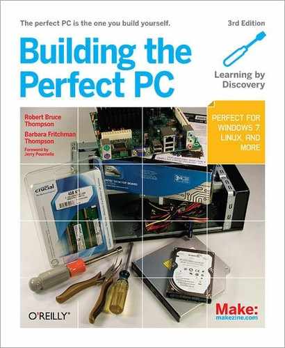
Figure 4-1 shows the major components of the mainstream system. The Antec EarthWatts EA-500D Green power supply is to the right of the Antec Mini P180 case, sitting atop the Intel DH55TC motherboard, with the Core i3-550 processor. The Antec Easy SATA hard drive docking station is to the far left, with Crucial 4 GB memory kit to its right. Front and center is the Sony/Optiarc DVD writer, with the Seagate Barracuda hard drive atop it.
Before you proceed, make sure you have everything you need. Open each box and verify the contents against the packing list.
Assembly Order
Although by necessity we describe building the system in a particular order, you don’t need to follow that exact sequence when you build your own system. Some steps—for example, installing the processor and memory before installing the motherboard in the case—should be taken in the sequence we describe, because doing otherwise makes the task more difficult or risks damaging a component. Other steps, such as installing the CPU cooler after you install the motherboard in the case, must be taken in the order we describe, because completing one step is a prerequisite for completing another. But the exact sequence doesn’t matter for most steps. As you build your system, it will be obvious when sequence matters.
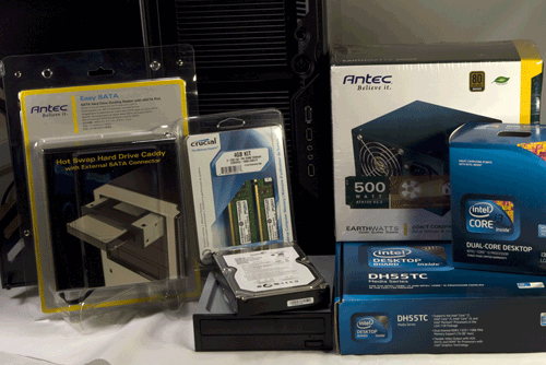
Figure 4-1. Mainstream system components, awaiting construction
Preparing the Case
Among the scores of models of computer cases we’ve used over the years, the Antec Mini P180, along with other members of the P180 family, is our favorite. Despite (or, more probably, because of) the 120 mm rear fan and the 200 mm (!) top fan, the Mini P180 is also one of the quietest cases we’ve ever used.
But if you’ve never used anything other than standard computer cases, the Antec P180-series cases take some getting used to. The first thing you’ll notice is the dual-chamber setup, with the power supply located in a separate chamber at the bottom of the case. Rather than having the various cables from the power supply simply hanging loose down into the main chamber, where you can route, connect, and dress them as needed, with the P180 you have to make some decisions about which cables you want to run where.
There are two options, which will become obvious when you look inside the open case. First, you can route cables from the power supply up through the bulkhead that separates the two chambers. Second, you can route power supply cables along the outside of the motherboard tray (below the motherboard, once it’s installed) and route them back into the main chamber through various cutouts.
The advantage to this more complex cable-routing setup is that you end up with a very clean build, with much less cable clutter, which in turn means better cooling and easier upgrades and repairs. The disadvantage is that you have to think things through beforehand, and you may end up having to go back and reroute one or more cables that you overlooked the need for initially before you finally get it right. On balance, we prefer this cable-routing method, but there’s no question that it takes some getting used to.
The exact cable routing you end up with will depend on the specific motherboard, power supply, and drives you use. For example, one power supply may have a main ATX power cable that’s long enough to route outside the main chamber and bring back in through a cutout, while a different power supply with a shorter main ATX power cable may require you to run that cable up through the bulkhead that divides the chambers.
Similarly, although the Mini P180 has three external 5.25” drive bays, one is located at the top of the case (in the main chamber) and the other two at the bottom (in the power supply chamber). But the top 5.25” drive bay is depth-constrained (by the body of the top 200 mm fan) to accept drives no deeper than 170 mm.
The upshot is that most current optical drives will fit the top bay, but some (notably some Blu-ray drives) must be mounted in one of the bottom bays. That may seem odd at first, but this system is most likely to be sitting on a desk, where having the optical drive in the lower part of the case is actually more convenient.
To get started preparing the case, remove the top and bottom thumbscrews from the right side panel, as shown in Figure 4-2. (Note the protective plastic film on the side panel; to prevent scratches, leave this film in place until you finish the build.)
Slide the right side panel back about an inch and lift it free of the chassis, as shown in Figure 4-3. Set the panel aside in a safe place.
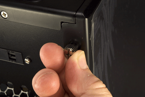
Figure 4-2. Remove the top and bottom thumbscrews from the right side panel
Figure 4-3. Slide the right side panel back an inch or so and remove it
Remove the two screws that secure the left side panel to the chassis, as shown in Figure 4-4. Lift the side panel free and put it aside in a safe place.
As with most cases, the Antec Mini P180 comes with an I/O shield installed, which fits no motherboard known to man. Press in on the outside of the I/O shield, as shown in Figure 4-5, until it snaps free. Discard the I/O shield.
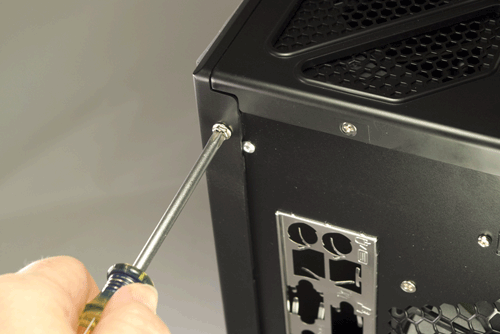
Figure 4-4. Remove the two screws that secure it, and then remove the left side panel
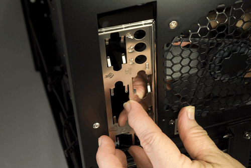
Figure 4-5. Remove and discard the I/O shield supplied with the case
Installing the Power Supply
The next step is to install the power supply in the lower chamber. To begin, remove the parts box, as shown in Figure 4-6, and set it aside. This box contains screws, spare cable ties, drive rails for the 5.25” drive bays, an adapter to secure a 3.5” drive in a 5.25” bay, and a bezel for a 3.5” drive that requires external access.
Release the cable wraps that secure the power supply cables into bundles. Extend and sort out the various cables, and leave them hanging loose for now. Working from inside the case, slide the power supply into position, as shown in Figure 4-7.
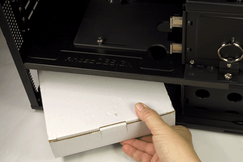
Figure 4-6. Remove the parts box and set it aside
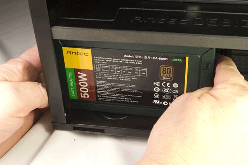
Figure 4-7. Slide the power supply into position
![]() Bottoms Up
Bottoms Up
The Antec EarthWatts EA-500D power supply we used has a fan at the back of the unit and a grill at the front of the unit, with the top and the bottom solid sheet metal. Some power supplies have a fan on the bottom of the unit. If your power supply is like that, mount it inverted, with the fan facing up. When the power supply is installed, the bottom is nearly in contact with the bottom of the case, with only thin antivibration/sound-deadening pads separating the power supply case from the bottom of the case.
Installing a bottom-vented power supply oriented normally will cause it to overheat. Inverting it allows the fan/vent to vent upward (where there is clearance), and will have no effect on the power supply. However, mounting the power supply inverted may make it awkward to insert the AC power cable or use the rear switch.
![]() Autosensing Versus Accident-Waiting-to-Happen
Autosensing Versus Accident-Waiting-to-Happen
The Antec EarthWatts EA-500D is autosensing, which means it adjusts itself automatically to accommodate 115VAC or 230VAC utility power. Many power supplies must be set manually using a slide switch to select the proper input voltage. Before you proceed further, check the back of your power supply for an input voltage selector switch. If one is present, make certain it’s set for the correct input voltage.
If you connect a power supply set for 230V to a 115V receptacle, no harm is done. The PC components will receive only half the voltage they require, and the system won’t boot. But if you connect a power supply set for 115V to a 230V receptacle, the PC components will receive twice the voltage they’re designed to use. If you power up the system, that overvoltage will destroy it instantly in clouds of smoke and showers of sparks.
Arrange the power supply cables neatly outside the right side of the case for the moment. Make sure none of the cables are trapped between the power supply and the chassis. Slide the power supply around until the four screw holes in the power supply align with the corresponding holes in the case. Drive the four provided screws to secure the power supply to the case, as shown in Figure 4-8.
You may want to preroute some of the power supply cables at this point, just to get them out of the way. If so, decide which power cables you want to route on the outer right side of the chassis, and which cutouts you want to route them through. (These cables will, of course, be covered when you reinstall the case cover.) Run those cables through the captive cable wrappers and the appropriate cutouts into the upper chamber, as shown in Figure 4-9. For now, don’t tighten the cable wrappers.
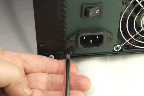
Figure 4-8. Secure the power supply to the case with four screws
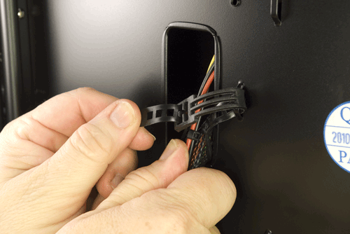
Figure 4-9. Route cables along the outer right side of the chassis and through the cutouts
Try, Try Again
Figure 4-9 shows Barbara routing the Main ATX power cable and a Molex cable that we intended to use to power the rear and top case fans. We later decided to run only the Main ATX power cable through that cutout. We ran a SATA power cable (for the optical drive) that also provided a Molex connector (for the case fans) through a cutout above the one visible in the figure.
For the time being, we won’t route the cables through the bulkhead that separates the upper and lower chambers. It’s easy to do that last, after the motherboard is installed, and keeping those cables out of the upper chamber makes it much easier to complete the motherboard installation.
Mounting the Optical Drive and Hard Drive
The Antec Mini P180 has two removable hard drive cages. The upper cage can hold three hard drives, mounted vertically and secured directly to the cage via screws driven through soft bushings. The lower cage can hold two hard drives, mounted with screws through soft bushings to removable drive trays.
Video Card Versus Drive Cages
If you intend to install a long video adapter card or other expansion card in your system, measure carefully. With the lower hard drive cage installed, there’s room for a card that’s at most 9.5” (241 mm) long. Even then, the card may interfere with the data and/or power cables for the hard drive.
Removing the lower drive cage increases clearance to more than 14”, even if you install a supplemental fan at the front of the cage area. (The longest video adapter card we’ve ever seen was less than 12”.) Of course, doing that also costs you two hard drive bays.
Fans Versus Drive Bays
The Antec Mini P180 provides two positions for mounting 120 mm supplemental fans, one in front of each of the hard drive cages. The problem is, if you install a fan, you can’t reinstall that drive cage. In other words, installing one of the supplemental fans costs you two or three hard drive positions, depending on the cage position in which you mount that fan. Installing two supplemental fans would cost you both removable hard drive cages and all five hard drive positions. (Although we suppose you could mount a hard drive or two in the lower 5.25” drive bays.)
Numerous user reviews on NewEgg, Amazon, and other sites comment negatively about this aspect of the Mini P180, but the reality is that Antec did not intend these supplemental fan positions to be used except in extraordinary circumstances. Many people are concerned about their hard drives running too hot without supplemental fans, but you really don’t need supplemental fans to cool the hard drive(s). With just the two standard case fans, our system ran cool and nearly silent. Running with the standard fan configuration for several hours, the temperature of our Seagate hard drive never exceeded 32° C (89.6° F).
Antec intended those supplemental fan positions to be used in two circumstances. First, if you’re running a very hot video adapter, you can remove the lower hard drive cage and install a 120 mm supplemental fan to cool the video card. Second, if you’re running a very hot processor, you can remove the upper hard drive cage and install a 120 mm supplemental fan in that position to cool the processor. If you’re running both a hot video card and a hot processor, you should probably use a different case.
Antec says, and we agree, that the supplemental cooling fans are seldom needed, and that installing them if they’re really not needed will simply increase the noise level of the system.
Even if you intend to install only one hard drive in your system, remove both drive cages. Like most μATX cases, the Antec Mini P180 has very limited working room. It’s easier to install the motherboard and make connections to it with both drive cages removed. To begin removing the drive cages, remove the thumbscrews, as shown in Figure 4-10.
Use a flat-blade screwdriver or similar tool to snap the pull rings free of their retaining clips and use the pull-rings to pull the drive cages straight out of the chassis, as shown in Figure 4-11.
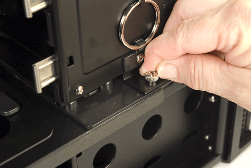
Figure 4-10. Remove the thumbscrews that secure the drive cages
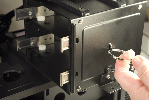
Figure 4-11. Pull the drive cages straight out of the chassis
The Antec Mini P180 manual claims that the parts box concealed on the right side of the upper 3.5” drive cage contains screws, spare grommets, standoffs, and so on. We’d already located those in the white cardboard box in the lower chamber, so we wondered what we’d find in that parts box. Figure 4-12 shows its contents. Yep, absolutely nothing.
Still, keep that parts box in mind. Once you finish assembling the system, you’ll have lots of leftover screws and other parts that you might need later. Ordinarily, we store those in a plastic bag taped to the floor of the case. The parts box is a neater way to store small spare parts.
Now, decide which drive cage you want to use. Directions follow for using either.
To install a hard drive in the lower drive cage, place the cage on a flat surface and remove one of the drive trays by squeezing both spring clips and sliding the drive tray out of the cage, as shown in Figure 4-13.
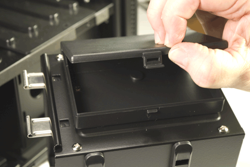
Figure 4-12. The parts box on the upper drive cage is a good place to store excess small parts
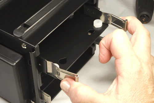
Figure 4-13. Squeeze both spring clips and slide the drive tray out of the lower drive cage
Place your hard drive inverted (circuit-board side up) on your work surface. Place the drive tray inverted on top of the drive, with the spring clip ends of the drive tray toward the data and power connector end of the hard drive. Align the drive tray so that the mounting holes in the hard drive are visible through the grommets in the drive tray. Locate the special hard drive mounting screws in the parts box. (One of these screws is visible at the lower center of Figure 4-14.) Drive four of these screws through the grommets and into the drive, as shown in Figure 4-14. Tighten the screws only finger-tight plus perhaps a quarter turn. Overtightening the screws reduces the isolation benefits of the grommets.
Orient the drive tray so that the solid base of the tray will be on the bottom when the drive cage is reinstalled. Slide the drive tray into the drive cage and press straight in until both spring clips snap into place, as shown in Figure 4-15.
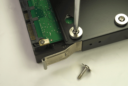
Figure 4-14. Secure the hard drive to the drive tray by driving four of the special hard drive mounting screws through the grommets

Figure 4-15. Slide the drive tray into the drive cage until the spring clips snap into place
We’re running neither a hot video adapter nor a hot processor, so we decided to leave both drive cages installed. We’re only installing one hard drive, at least for now, so we decided to install it in the upper removable drive cage, leaving the more accessible lower cage available for easier later upgrades. If you decide to use the upper hard drive cage, you’ll find it a bit harder to install the drive(s) because they’re unsupported and more difficult to keep aligned until you drive in a couple of screws to secure them.
Place the drive cage on its side and use one hand to support the drive and line up the top two screw holes in the drive with the holes in the grommets. Drive in two of the special screws (visible in Figure 4-16) to keep the drive in position. Invert the drive cage to place the unsecured side of the drive on top, as shown in Figure 4-16. Nudge the drive back and forth until one of the screw holes aligns with a grommet hole and drive in that screw. Repeat that process with the fourth screw.
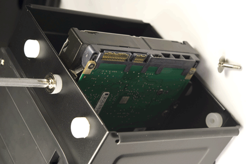
Figure 4-16. Use four of the special hard drive screws to secure the hard drive directly to the upper drive cage
Once the hard drive is installed in the drive cage, set both drive cages aside for now. We’ll reinstall the drive cages after we install and connect the motherboard.
The next step is to install the optical drive. Antec recommends installing it, if possible, in the top 5.25” external drive bay. To begin, use your index fingers to grasp the sides of the plastic drive bezel and twist it until it snaps out, as shown in Figure 4-17.
Insert the tip of a flat-blade or Phillips screwdriver in the hole in the center of the steel RF shield inside the drive bay and twist it back and forth, as shown in Figure 4-18, until the metal plate snaps free.
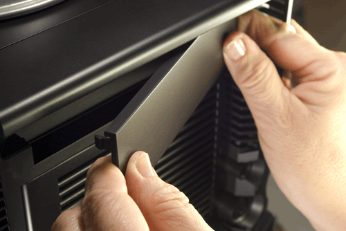
Figure 4-17. Snap out the top 5.25” drive bay bezel
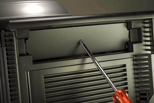
Figure 4-18. Twist the metal RF shielding plate until it snaps free
Locate two drive rails and four optical drive mounting screws in the parts box. Stand the optical drive on its side on your work surface, and align one of the drive rails with the mounting holes in the side of the optical drive. Position the drive rail so that it is about centered vertically on the side of the optical drive, with the front of the metal spring tab flush with the front bezel of the drive. Insert two screws to secure the drive rail to the optical drive, as shown in Figure 4-19. Repeat this procedure to install the second drive rail.
Position the optical drive in the drive bay and slide it into the drive bay, as shown in Figure 4-20, until the spring clips on both drive rails snap into place. Verify that the front bezel of the drive is seated flush with the front bezel of the case.
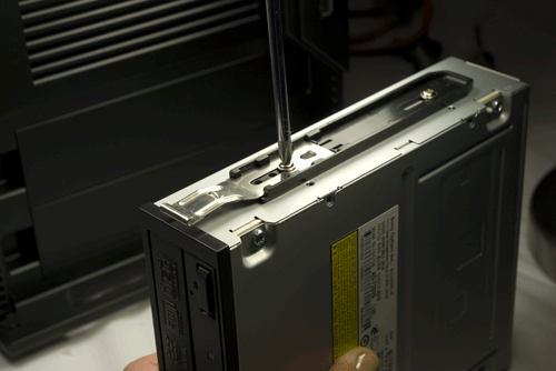
Figure 4-19. Use two screws to secure the drive rail to the optical drive

Figure 4-20. Slide the optical drive into the bay and press until both spring clips on the drive rails snap into place
If the drive refuses to slide all the way into the bay, verify that the top fan assembly isn’t preventing it from doing so, as shown in Figure 4-21. The top external 5.25” drive bay accepts drives with a maximum depth of 170 mm (about 6.7”). The Sony Opticarc DVD writer shown in the image clears by about 5 mm. Even if your drive seats completely, check out the back of the drive to make sure the fan doesn’t interfere with the data or power connectors on the back of the drive.

Figure 4-21. Verify that the top fan assembly doesn’t interfere with the optical drive
If your drive does not seat completely, or if the top fan structure interferes with the power or data connectors on the drive, your only options are to use a different optical drive or to mount that drive in one of the lower 5.25” external drive bays.
Note the cutout in the motherboard tray, visible in Figure 4-21 just below the top fan and to the left of the drive connectors. We’ll use that cutout to route the SATA power cable and data cable to the optical drive.
Preparing the Motherboard
The next step is to prepare the motherboard by installing the processor, CPU cooler, and memory. Despite the fact that some case and motherboard manuals suggest installing these components after the motherboard has been installed in the case, it’s easier and often safer for the motherboard to mount the processor, cooler, and memory first.
To begin, locate the processor socket. Ground yourself by touching the power supply, and then release the chrome metal socket lever by pressing it down and away from the socket body. Once it’s free of the catch on the socket body, lift the lever to the straight vertical position, which also raises the load plate to its fully open position, exposing the socket. Snap out the black plastic socket cover and store it with the other small parts in the parts box. If you ever remove the processor from the socket, replace the socket cover to protect the fragile socket contacts.
Open the processor package. Once again, ground yourself to the power supply or chassis frame before you touch the processor itself. Snap off the black plastic processor cover and set it aside. Store the processor cover later for possible future use.
Pin 1 on the processor is indicated by the gold triangle visible on the lower-left corner of the processor in Figure 4-22. Pin 1 on the socket is indicated by a beveled corner on the socket body. The processor and socket are further keyed by two notches on the outer edge of the processor to accommodate the two corresponding posts on the inside edge of the socket. Make sure pin 1 on the processor and the socket are aligned and that both keying notches are aligned with the corresponding posts, and then drop the processor straight into the socket, as shown in Figure 4-22.
Leave the socket lever in the fully open (vertical) position as you lower the load plate into the closed position, as shown in Figure 4-23.
Lower the processor lever slightly, which cams the load plate into locked position. Make sure that the notch on the front of the load plate mates with the shoulder screw cap, as shown in Figure 4-24.
Continue lowering the processor lever (which takes noticeable pressure) and snap it into place under the latch on the load plate, as shown in Figure 4-25.
Examine the surface of the processor carefully. If there are any fingerprints, dust, or other contaminants present, use a clean paper towel to polish the surface of the processor, as shown in Figure 4-26.
Remove the CPU cooler from the processor box and examine the bottom of the cooler. The gray patches visible in Figure 4-27 on the copper bearing surface of the cooler are phase-change thermal compound. (Phase-change is just a fancy way to say that the stuff melts each time the processor heats up and solidifies when the processor cools down.) The thermal compound ensures good heat transfer between the surface of the processor and the base of the heatsink.
If any of those patches are missing or damaged, carefully rub the remaining patches off the copper surface and replace them with an approved thermal paste. If you ever have to remove and replace the processor, don’t reuse the existing thermal compound. Rub off any remaining residue from both the processor surface and the heatsink base, and replace it with new thermal compound. (We keep a tube of Antec Silver thermal compound on hand for just this purpose.)
The CPU cooler mounts to the motherboard using four push-posts with twist locks. The tips of the posts protrude a few millimeters on the back side of the motherboard, so you can’t install the CPU cooler with the motherboard on a hard surface. We simply tilted the motherboard slightly while mounting the cooler to give clearance for the posts.
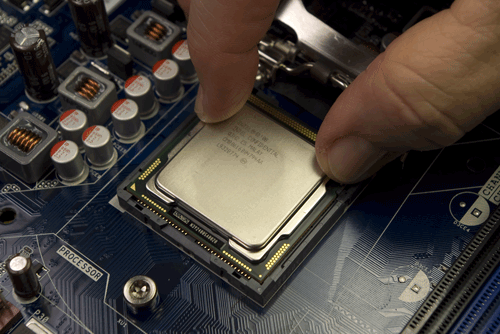
Figure 4-22. Align the processor with the socket and then drop the processor into the socket
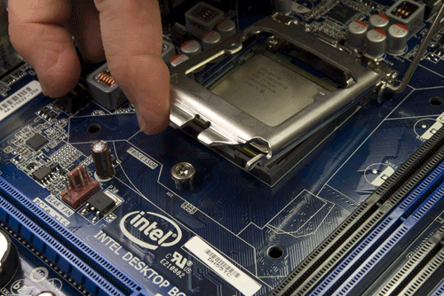
Figure 4-23. Lower the load plate into the closed position
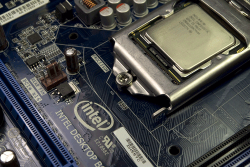
Figure 4-24. Lower the processor lever to cam the load plate into locked position
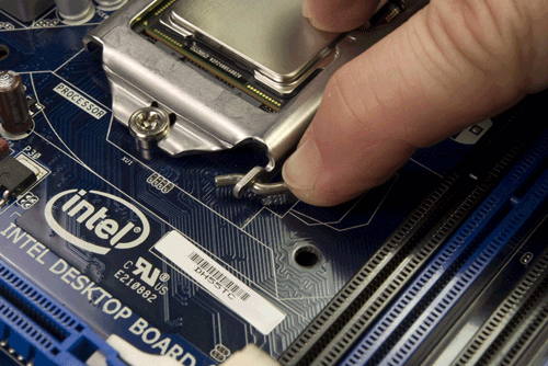
Figure 4-25. Close the processor lever completely and snap it into the latch on the load plate
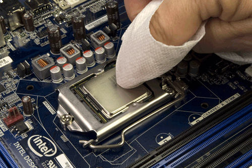
Figure 4-26. If necessary, polish the surface of the processor with a clean paper towel
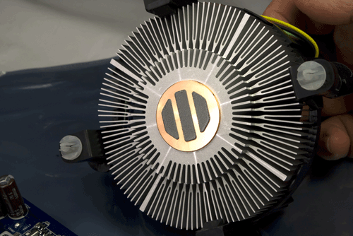
Figure 4-27. Verify that the thermal compound is present and undamaged on the base of the heatsink
To install the CPU cooler, align the tips of its four posts with the four mounting holes in the motherboard. The four mounting posts/holes form a square, so you can orient the CPU cooler in any of the four possible positions and still mount it successfully. We recommend positioning the CPU cooler so that the power cable for the CPU fan reaches the connector on the motherboard with minimum cable slack. Once you have the four posts and holes aligned, press down firmly on one post, as shown in Figure 4-28, until you feel it snap into place.
After you have snapped all four posts into place, you need to lock them. The top of each CPU cooler post has an arrow to indicate which direction to turn it to lock the post into place. Figure 4-28 shows the cap of a CPU post before it has been twisted to the locked position. You can use your fingers to turn the posts to the locked position, but it’s easier to use a flat-blade screwdriver, as shown in Figure 4-29. Lock all four of the posts. Figure 4-30 shows a cap in locked position.
The final step in installing the CPU cooler is to connect the CPU fan power cable to the CPU fan power header pins on the edge of the motherboard, as shown in Figure 4-31. Make sure the keys on the connector bodies match, and then slide the connector onto the pins until it seats.
Ron Morse Comments
The Intel-supplied CPU cooler uses a variable-speed fan with a four-pin power connector. The system controls the fan’s operating speed (and the amount of noise it makes) in concert with the operating temperature of the CPU. Make sure you connect the CPU fan to the four-pin header on the motherboard labeled “CPU FAN.”
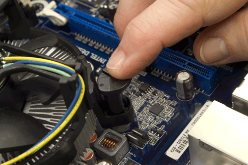
Figure 4-28. Align the CPU cooler posts with the motherboard mounting holes and press down on the tops of the posts until they snap into position
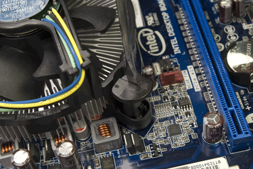
Figure 4-29. Turn the cap of each CPU cooler post in the direction of the arrow to lock it into place
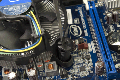
Figure 4-30. A CPU cooler post cap in locked position
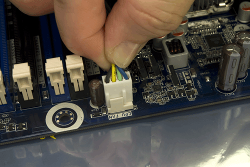
Figure 4-31. Connect the CPU fan power cable to the CPU fan power header pins
With the processor and CPU cooler installed, the next step is to install the memory modules. To begin, open all eight of the memory slot latches by pivoting them outward and down, away from the memory slots, as shown in Figure 4-32.
The DH55TC motherboard has four memory slots that accept 240-pin DDR3 memory modules. These slots are arranged in two channels, each of which accepts two DIMMs. Channel A is the pair of slots nearest the processor, and Channel B the two slots nearest the main ATX power connector (visible at the bottom left of Figure 4-33). The blue slot is DIMM 0 for each channel, and the black slot is DIMM 1.
If you are installing a matched pair of memory modules, install them in the two blue (DIMM 0) slots. If you are installing four DIMMs in two matched pairs that differ from each other, install the larger matched pair in the two blue (DIMM 0) slots and the smaller matched pair in the black (DIMM 1) slots. (Obviously, if all four DIMMs are identical it doesn’t matter which DIMM goes in which slot.) If you are installing three DIMMs comprising a matched pair and one odd DIMM, install the matched pair in the two blue (DIMM 0) slots, and the third DIMM in either black (DIMM 1) slot.
In any case, install the DIMMs that will occupy the slots nearest the processor first and work forward toward the edge of the board. Before touching a DIMM, ground yourself by touching the power supply or chassis frame. Hold the first DIMM vertically over the appropriate slot. Align both edges of the DIMM with the slots in the vertical posts on the sides of the DIMM slot. DDR3 DIMMs are keyed with an off-center notch on the bottom (contact) edge of the DIMM. Make sure this notch aligns with the corresponding post in the slot, and then slide the DIMM into position, as shown in Figure 4-33.
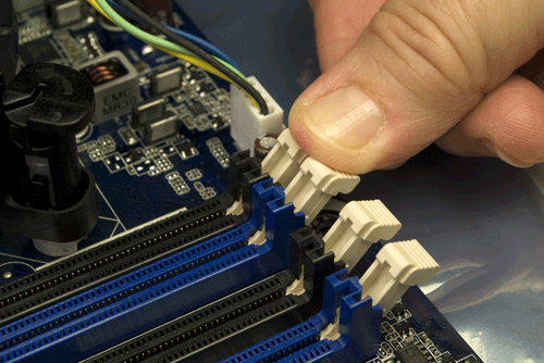
Figure 4-32. Open the memory slot latches
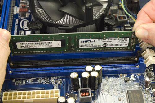
Figure 4-33. Holding the DIMM vertically, align it with the slot and key and slide it into position
Once the DIMM is aligned properly, seat it by placing one thumb on each side of the DIMM and pressing down firmly until you feel it snap into place, as shown in Figure 4-34. Although it’s better to seat the DIMM by pressing on both ends simultaneously, if you can’t get the DIMM to snap into place this way, you can press down first on one end and then the other until it seats completely. Repeat this procedure to install any remaining DIMMs.
Verify that the DIMM is fully seated, as shown in Figure 4-35. If the DIMM is seated properly, none of the contacts on the bottom edge of the module should be visible, and the DIMM latching posts should snap up into the latched position. (If the module is fully seated but the DIMM latching posts remain open, manually close them to engage the notches on the edges of the DIMMs.)
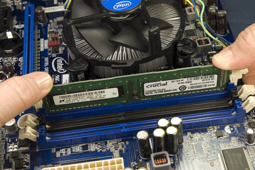
Figure 4-34. Use both thumbs to press down firmly until the DIMM snaps into place
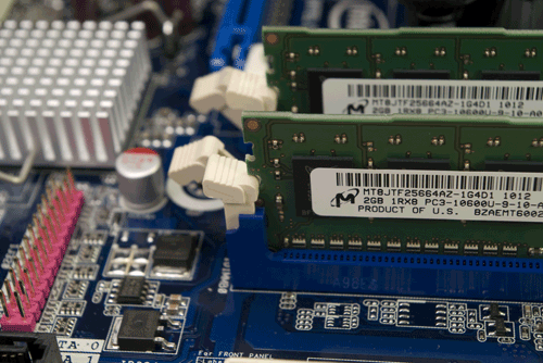
Figure 4-35. Verify that the DIMMs are fully seated and the latching posts are in the latched position
Installing the Motherboard
With the motherboard populated, the next step is to install it in the case.
Ordinarily, we’d have already compared the I/O shield with the motherboard’s back-panel I/O port to make sure they matched and then installed the I/O shield in the case.
We started to do it that way for this system, but we immediately ran into a problem. There is so little clearance for the DH55TC motherboard that we simply couldn’t fit the motherboard into the case with the I/O shield installed. Well, we suppose we could have, but doing that would have required removing and reinstalling the rear case fan. That we could have done at the cost of a few extra minutes’ work, but it also appeared that we’d have to remove and replace the shelf that supports the two internal hard drive cages, and that shelf is riveted.
As we sat there considering our alternatives, our gaze settled on the rear of the Mini P180 case, shown in Figure 4-36 with the motherboard already installed. Hmmm. Four expansion slot covers that are mostly holes, and a good-sized grill to ventilate the expansion slots. A 120 mm fan grill. And that’s not even counting the honking huge 200 mm fan grill at the top rear of the case. This area of the Antec Mini P180 is mostly open to the air anyway, and we concluded that the small additional gap produced by leaving out the I/O shield wouldn’t noticeably affect air flow, cooling, or noise level. So, for the first time since Intel introduced the ATX form factor in 1995, we decided to build a system without installing the I/O shield. (Later testing showed that both the processor and hard drive were running very cool, so we have no concerns about omitting the I/O shield.)
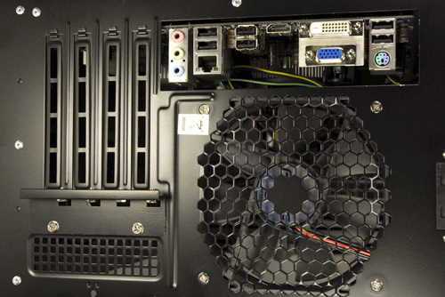
Figure 4-36. Leaving out the I/O shield doesn’t greatly increase the open area of the Antec Mini P180 case
With that decision made, building the system suddenly became a lot easier. Of course, if you use a different case or motherboard, you may have sufficient clearance with the I/O shield in place. Or you may not.
The Intel DH55TC motherboard has eight mounting holes. The Antec Mini P180 case comes with six standoffs preinstalled, so the first step in installing the motherboard is to determine which, if any, of the standoffs are incorrectly positioned and which motherboard mounting holes need additional standoffs installed. To answer those questions, temporarily lower the motherboard into position, as shown in Figure 4-37, and note the locations that require standoffs.
As it turns out, all six of the preinstalled standoffs in the Antec Mini P180 correspond to mounting holes in the Intel DH55TC motherboard. Two motherboard mounting holes have no corresponding standoffs, so we installed standoffs in both of those positions, as shown in Figure 4-38.
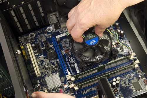
Figure 4-37. Place the motherboard in position to determine the locations where standoffs need to be installed
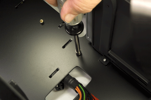
Figure 4-38. Install any missing standoffs needed to support the motherboard
Once all standoffs are installed, again lower the motherboard into position and make a final check that a standoff is installed for each motherboard mounting hole and that no extra standoffs are present. From the parts box, locate the small plastic bag labeled “Motherboard only” and remove eight motherboard mounting screws. Position the motherboard so that at least one standoff is visible through a mounting hole and partially drive a motherboard mounting screw into that standoff. Realign the motherboard as needed to line up the other mounting holes with their corresponding standoffs, and drive screws into each standoff, as shown in Figure 4-39. Tighten all screws finger-tight plus about a quarter turn. Do not overtighten the screws, or you risk cracking the motherboard.
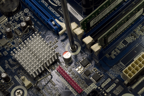
Figure 4-39. Drive screws into all eight standoffs to secure the motherboard
Connecting power to the motherboard
The next step is to connect the ATX12V power cable to the motherboard. This cable has a 2×2 keyed connector with two black (ground) wires and two yellow (+12V) wires, and includes a latch. The Antec EarthWatts EA-500D power supply labels these connectors “P2,” but other power supplies may label them “CPU” or “ATX12V.”
More Power
Many power supplies (including the EA-500D) provide two ATX12V connectors. Some high-current processors draw more +12VDC than one ATX12V connector can supply. Motherboards designed for those processors have either two of the four-pin connectors or one eight-pin connector that will accept two four-pin cables.
Locate the ATX12V cable bundle coming out of the power supply and route that cable up the outside of the case on the righthand side to the cutout at the top of the motherboard tray. Pass one of the ATX12V connectors into the top chamber of the case and connect it to the motherboard, as shown in Figure 4-40. Make sure the keying on the plug and socket match properly, and then press the connector down until the latch snaps into place.
If you haven’t already done so, locate the 24-pin main ATX power connector cable coming out of the power supply, and route it up the outside of the case (on the right) to the cutout nearest the main ATX power connector at the front edge of the motherboard. Align the plug with the socket, making sure the keying matches. Press down firmly on the plug, as shown in Figure 4-41, until you feel it seat completely in the socket and the latch engages.
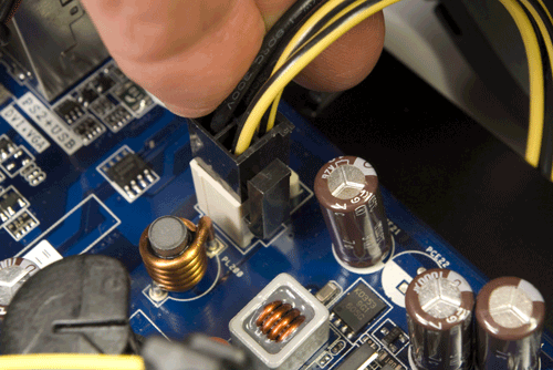
Figure 4-40. Connect the ATX12V power cable to the motherboard
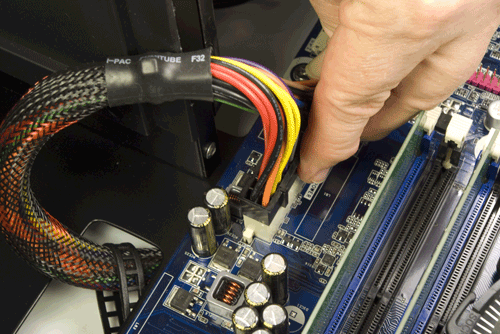
Figure 4-41. Connect the main ATX power cable to the motherboard
Connecting front-panel ports, switches, and indicators
The Antec Mini P180 case provides front-panel ports for USB, HD or AC’97 audio, and eSATA. Oddly, neither the Mini P180 case nor the Intel Media Series motherboard provides an IEEE 1394/FireWire port—or perhaps those are simply indications of the declining importance of FireWire for desktop systems in an environment where eSATA is commonplace and USB 3.0 will soon become so. It wouldn’t surprise us at all if the next HD camcorder we buy has eSATA and/or USB 3.0 ports instead of FireWire.
To begin connecting the front-panel ports, locate the front-panel audio cable. This cable has two connectors—one for HD audio and one for AC’97 audio—to accommodate motherboards with either type of audio connector. Our motherboard provides an HD audio connector, so that’s what we’ll use. Locate the front-panel HD audio header-pin set, toward the rear corner of the motherboard, near the expansion slots. The header-pin set is keyed with a missing pin that corresponds to a blocked hole on the cable connector. Orient the cable connector and header pins so that the keying matches, and then press the cable connector onto the header pins, as shown in Figure 4-42.
In addition to six rear-panel USB ports, the Intel DH55TC motherboard includes three sets of header pins that each provide two USB ports, for a total of 12 USB ports. The center USB header-pin set also includes special support for an internal embedded USB (eUSB) solid-state drive.
eUSB?
Embedded USB SSDs are not used in general-purpose PCs. They were designed to replace 1.8” hard drives in embedded, ruggedized, and mil-spec systems, where they serve as the only mass storage device. eUSB SSDs generally use expensive SLC memory and have capacities in the 500 MB to 16 GB range. A 1 GB eUSB SSD may cost $35, a 4 GB model $125, and a 16 GB model $500.
We don’t expect to install an SSD in this system, and if we did it would be one that uses a standard SATA interface. Even so, with more USB ports on the motherboard than we have places to connect them, we decided to use one of the remaining two USB header-pin sets. One of those sets is located near the front corner of the motherboard, in close proximity to the front-panel switch and indicator pins. To make it easier to install the latter, we decided to use the second USB header-pin set, located just to the rear of that first set.
Like the front-panel audio connectors, the USB cable connector and header-pin set are keyed with a blocked hole and missing pin, respectively. (The USB key pin is different from the audio key pin, to make sure you can’t accidentally connect a USB port to the audio header pins, or vice versa.)
To make the connection, orient the front-panel USB cable plug to align its blocked hole with the missing pin on the USB header-pin set. Slide the cable connector down onto the header pins, as shown in Figure 4-43, until it seats completely.
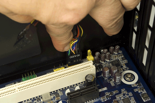
Figure 4-42. Connect the front-panel audio cable HD audio connector to the FP audio header-pin set
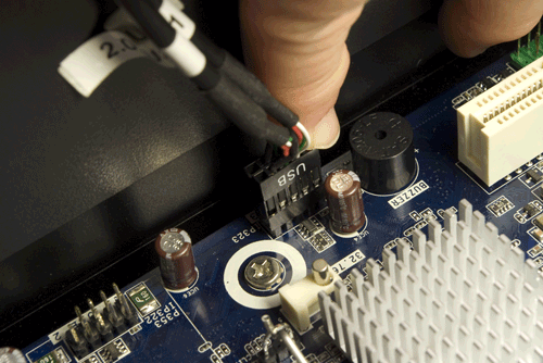
Figure 4-43. Connect the front-panel USB cable connector to the USB header-pin set
Next up are the front-panel switch and indicator cables: namely, the power and reset switches, the hard drive activity LED, and the power LED. Figure 4-44 shows the pinouts for these switches and indicators on the Intel DH55TC motherboard. (Actually, this is an Intel standard, used by all recent Intel motherboards and most motherboards from other makers.)
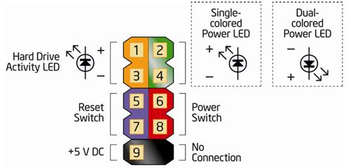
Figure 4-44. Intel DH55TC front-panel switch and indicator pinouts (image courtesy of Intel Corporation)
We’ll connect three of those cables to the monolithic connector block mapped in Figure 4-44. The one exception is the power LED, because Intel provides two adjacent pins for that connection, while the Antec Mini P180 case provides a three-position/two-pin power LED cable that does not fit this block. Fortunately, the Intel DH55TC motherboard provides an alternative three-position/two-pin motherboard connector that the Antec cable fits. That connection is shown at the bottom center of Figure 4-45 as a blue/white cable connected to the pin set labeled PWR LED. Connect the power switch cable and reset switch cable to the monolithic connector block, as shown in Figure 4-45. Polarity doesn’t matter for switches, so you can install the cable connector in either direction. Connect the HDD LED cable to the appropriate pins, making sure to observe polarity. (The red wire is positive and the white wire is ground.) If you connect this cable backward, no harm is done, but the HDD LED won’t function.
Locate the black front-panel eSATA cable, and connect it to one of the red eSATA motherboard ports as shown in Figure 4-46. It doesn’t matter which one. Make sure the L-shaped key in the cable connector and motherboard connector mate, and then press the cable connector down firmly until it seats.
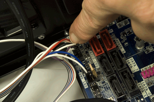
Figure 4-45. Connect the front-panel switch and indicator cables
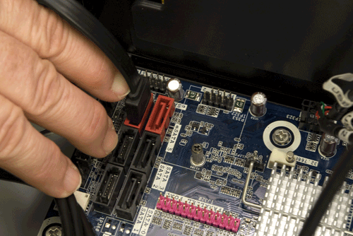
Figure 4-46. Connect the front-panel eSATA cable
Installing the Antec Easy SATA Docking Station
The next step is to install the Antec Easy SATA hard drive docking station. At first glance, it might seem that installing the Easy SATA presents a resource-allocation conflict. The Intel DH55TC motherboard provides two eSATA-enabled ports. The front-panel eSATA port that we just connected uses one of those eSATA motherboard ports, leaving us with only one available.
But the Antec Easy SATA unit requires two more motherboard SATA connectors. One of those connects to the Easy SATA using a standard SATA data cable. The second connects via the captive cable (shown in Figure 4-47) to the external eSATA port on the front bezel of the Easy SATA unit. So it appears that we need a total of three eSATA motherboard ports, one more than we have.
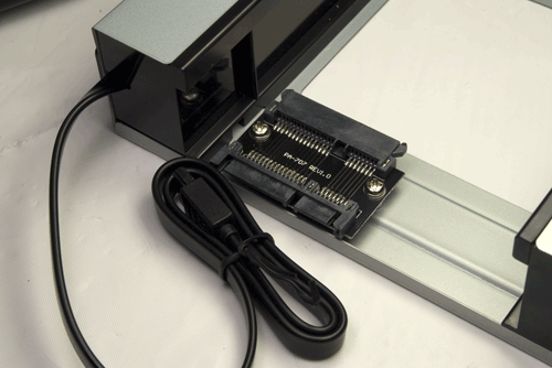
Figure 4-47. Power and data connectors on the rear of the Antec Easy SATA hard drive docking station
At this point, we wondered exactly what the difference was between the red eSATA motherboard ports and the black standard SATA motherboard ports. The connectors appear identical except for color, and they accept the same cables. We examined the ports closely to see if there were any physical differences—for example, different pin lengths to support hot-plugging—but could see no differences at all.
So we asked one of our technical contacts at Intel, who explained it all to us. The only difference between the red eSATA motherboard connectors and the black standard SATA motherboard connectors is the signal level. The red connectors use a slightly higher signaling voltage to allow using the longer cables supported by the eSATA specification. The higher voltage on the red ports won’t harm standard SATA devices, and eSATA devices work properly on the black ports if the cable lengths are kept short. So, as it turned out, we didn’t have a problem at all. We connected the two red eSATA motherboard ports to the eSATA jacks on the Mini P180 case and the front bezel of the Antec Easy SATA unit. We then used a standard black SATA motherboard port to connect the removable drive bay portion of the Easy SATA.
To install the Antec Easy SATA hard drive docking station, follow the same procedure described in the section about mounting the optical drive to remove the plastic bezel and steel RF shielding plate from one of the lower 5.25” drive bays. Attach drive rails to each side of the Easy SATA frame, as shown in Figure 4-48. Both rails should be positioned as shown, using the upper set of screw holes in the Easy SATA frame and with the front edge of the spring clips flush with the front bezel.
Locate one of the SATA power cables from the power supply cable bundle, and feed it through the lower 5.25” external drive bay and out the front of the case. Match the L-shaped keys on the power cable connector and the Easy SATA power connector, and press the power cable connector onto the Easy SATA power connector, as shown in Figure 4-49.
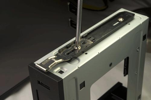
Figure 4-48. Attach drive rails to both sides of the Antec Easy SATA hard drive docking station
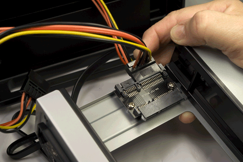
Figure 4-49. Connect power to the Easy SATA unit
Feed a standard SATA data cable through the lower drive bay and connect it to the data connector on the Easy SATA unit, as shown in Figure 4-50.
Make sure the SATA power cable and both SATA data cables will feed through the drive bay opening and into the lower interior chamber, and then slide the Antec Easy SATA unit into the drive bay, as shown in Figure 4-51.
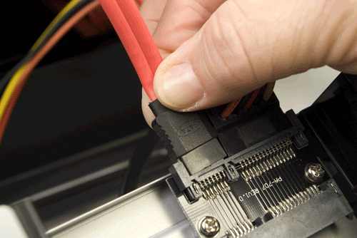
Figure 4-50. Connect a standard SATA data cable to the Easy SATA data connector
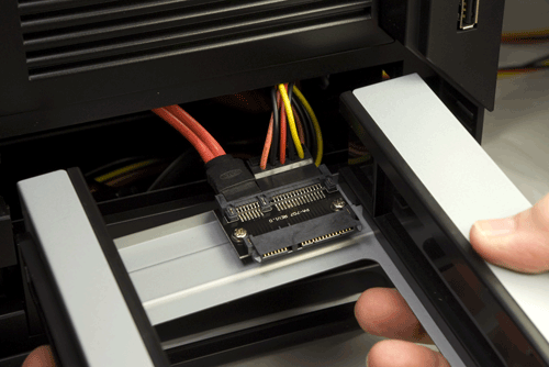
Figure 4-51. Slide the Easy SATA unit into the drive bay
Although the Easy SATA frame slides in and out of the bay easily, you may have to use some pressure to force the frame rails to snap into the latched position. Note in Figure 4-52 that the spring clips are still in the unlatched position, tight against the side of the Easy SATA frame rather than projecting out into the thumb holes. To get the frame to seat and latch, we had to withdraw it an inch or two and then slide it quickly into place. Make sure these spring clips latch, or the first time you attempt to remove a hard drive from the frame the whole frame will slide out of the case.
Locate the two SATA data cables in the lower chamber at the rear of the Easy SATA and feed them up through the hole in the sliding door of the interior bulkhead, as shown in Figure 4-53. (The thumbscrew can be loosened if you need to slide that door aside temporarily to route cables.)
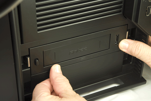
Figure 4-52. Press the Easy SATA frame into the drive bay until the spring clips snap into place
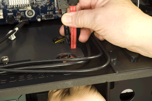
Figure 4-53. Route the two SATA data cables from the Easy SATA through the bulkhead and into the upper chamber
The black captive SATA data cable from the Easy SATA unit feeds the eSATA port on the front of the unit. Because that port may be used to connect an external eSATA device with a long cable, we want to connect the black captive cable to our one remaining motherboard eSATA port, as shown in Figure 4-54. (Yes, it’s bass-ackwards that we’ve now connected two black SATA cables to our two red motherboard SATA ports and we’re about to connect red SATA cables to our black motherboard SATA ports. Oh, well.)
The standard SATA data cable from the Easy SATA unit feeds the removable drive bay, which in terms of required signal strength is the same as any internal SATA device. That means we can connect it to any of the four standard SATA ports on the motherboard. We reserved SATA 0 and SATA 1 ports for our hard drive and optical drive, so we decided to connect the Easy SATA data cable to the next available SATA port, SATA 2.
Match the L-shaped keys on the cable connector and motherboard connector, and then press the cable connector into place, as shown in Figure 4-55. Make sure the cable connector seats fully, and that the cables you connected previously are still seated.
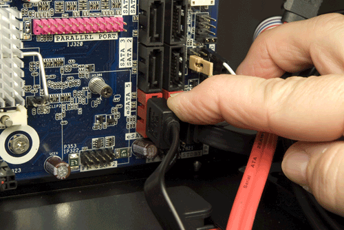
Figure 4-54. Connect the black captive SATA data cable from the Easy SATA unit to the one remaining motherboard eSATA port
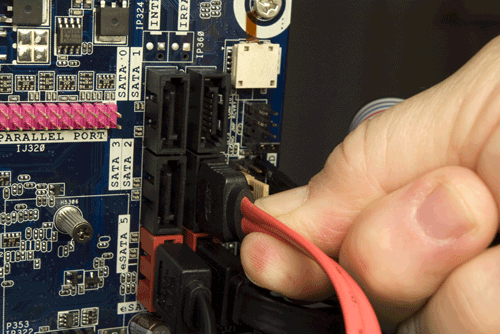
Figure 4-55. Connect the standard SATA data cable from the Easy SATA unit to one of the standard SATA motherboard ports
Connecting Power and Data Cables to the Optical Drive and Hard Drive
We’re in the home stretch now. All that remains is to connect the power and data cables to the optical drive and hard drive, and do a bit of neatening up. To begin, locate a SATA power cable that also includes a Molex connector. Route that cable up the exterior right side of the case, and pass a SATA power connector through the cutout at the top of the case, nearest the optical drive. Make sure the keying on the cable connector and optical drive connector match up, and then press the SATA power cable connector firmly onto the optical drive power connector, as shown in Figure 4-56.
Pass a standard SATA data cable through the same cutout you used for the power cable, and then connect the SATA data cable to the optical drive, as shown in Figure 4-57.
Run the SATA data cable down the outside of the case on the right, and pass it through the cutout nearest the motherboard SATA connectors. Make sure the keying on the cable and motherboard connector match, and then press the cable connector onto the motherboard connector, as shown in Figure 4-58. Make sure the cable connector seats completely.
Slide the hard drive cage back into the chassis and secure it by reinstalling the thumbscrew. Route a SATA power cable to the hard drive, and connect it, as shown in Figure 4-59.
Connect a standard SATA data cable to the hard drive, as shown in Figure 4-60.
Route the hard drive data cable to the motherboard SATA port area and connect the SATA data cable to a motherboard SATA port, as shown in Figure 4-61. (Yes, we got tired of using all black and red SATA data cables, so we fished out a silver one for the hard drive.)
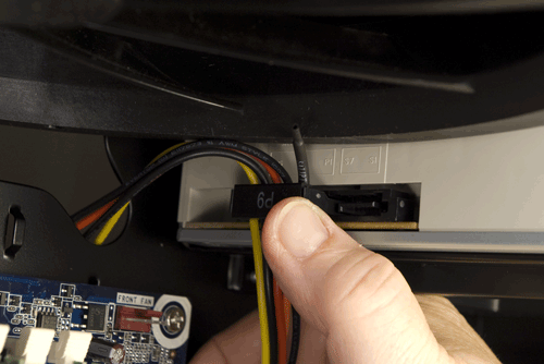
Figure 4-56. Connect a SATA power cable to the optical drive
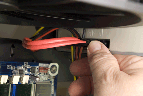
Figure 4-57. Connect a standard SATA data cable to the optical drive
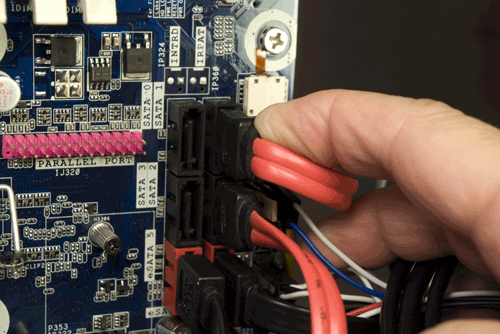
Figure 4-58. Connect the SATA data cable from the optical drive to a motherboard SATA port
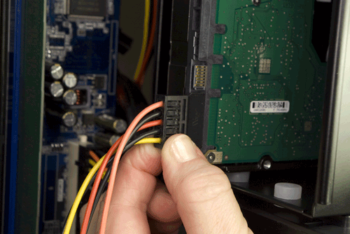
Figure 4-59. Connect a SATA power cable to the hard drive
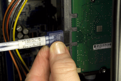
Figure 4-60. Connect a standard SATA data cable to the hard drive
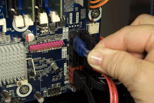
Figure 4-61. Connect the hard drive SATA data cable to a motherboard SATA port
Finally, route a SATA power cable to the hard drive and connect it, as shown in Figure 4-62. At this point, the system is complete except for some minor cleanup.
Even though we’ve built several systems with Antec P180-series cases, we’re always surprised when we finish one and see how neat the cabling is. Figure 4-63 shows the finished mainstream system, with almost no cable mess. Well, we do plan to do something about that CPU fan power cable and perhaps tuck the SATA power cables to the optical drive and hard drive into the hard drive cage, but otherwise there’s no cable dressing remaining to be done inside the main chamber.
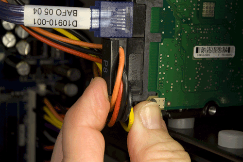
Figure 4-62. Connect a SATA power cable to the hard drive
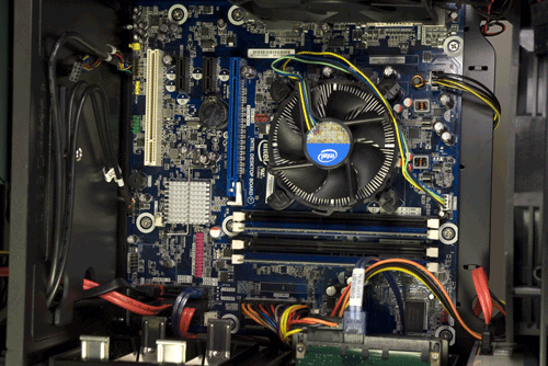
Figure 4-63. The interior of the mainstream system, seconds after we finished connecting cables
Of course, when Robert was a teenager, he tried to fool his mother, who had told him to clean up his room. He simply piled everything in the closet, which worked well until she opened the closet door. Figure 4-64 shows that bedroom closet for our mainstream system—the rats’ nest of cabling on the exterior right side of the case. Fortunately, it’s not as bad as it looks.
Note that unused Molex power connector hanging loose near the QA PASS label. We left that there to remind us to connect power to the case fans. Do so now, as shown in Figure 4-65.
To dress the messy side of the motherboard tray, first feed any excess cabling back from the main chamber to this side of the tray. Gather and bundle the cables, and secure them using the captive cable ties and the spare cable ties from the parts box.
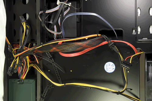
Figure 4-64. The hidden rats’ nest of cables
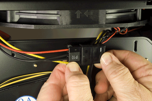
Figure 4-65. Connect power to the case fans
Final Assembly Steps
Congratulations! You’re almost ready to put the side panels back on the case and declare the system finished.
Before you do that, take a few minutes to double-check everything. Verify that all cables are connected properly, that all drives are secured, and that there’s nothing loose inside the case. If your power supply is not autosensing, check one last time to verify that it is set to the correct input voltage. It’s a good idea to pick up the system and tilt it gently from side to side to make sure there are no loose screws or other items that could cause a short. Use the following checklist:
Power supply set to proper input voltage (if applicable)
No loose tools or screws (shake the case gently)
CPU cooler properly mounted; CPU fan connected
Memory modules fully seated and latched
Front-panel switch and indicator cables connected properly
Front-panel I/O cables connected properly
Hard drive data cable(s) connected to drive(s) and motherboard
Hard drive power cable(s) connected
Optical drive data cable connected to drive and motherboard
Optical drive power cable connected
All drives secured to drive bay or chassis, as applicable
Expansion card(s) (if any) fully seated and secured to chassis
Main ATX power cable and ATX12V power cable connected
Top and rear case fans connected
All cables dressed and tucked
Once you’re certain that all is as it should be, it’s time for the smoke test. Leave the cover off for now. Connect the power cable to the wall receptacle and then to the system unit. Unlike many power supplies, the Antec unit has a separate rocker switch on the back that controls power to the power supply. By default, it’s in the “0” or off position, which means the power supply is not receiving power from the wall receptacle. Move that switch to the “1” or on position. Press the main power button on the front of the case, and the system should start up. Check to make sure that all fans are spinning. You should also hear the hard drive spin up. At that point, everything should be working properly.
False Starts
When you turn on the rear power switch, the system will come to life momentarily and then die. That’s normal behavior. When the power supply receives power, it begins to start up. It quickly notices that the motherboard hasn’t told it to start, though, so it shuts down again. All you need to do is press the front-panel power switch and the system will start normally.
At this point, the system is ready to roll. Turn it off, replace the side panels, and strip off any remaining protective plastic film. Move the system to where you plan to use it, connect the display and other external peripherals, fire it up, install your operating system and applications, and restore your data to the new system.
Final Words
Other than the minor issue with the I/O shield and a couple of false starts routing cables, this system went together easily. Not counting the time needed to shoot the images, it took us about 30 minutes from start to finish. A first-time system builder should be able to assemble this system in an evening with luck, and certainly over a weekend.
We’re very pleased with our new mainstream system. Despite the numerous large vents and fan grills, the system is extremely quiet—enough so that it’s inaudible in a normal room when we’re sitting only a couple of feet away. We set both the top and rear fans to slow initially, using the fan switches on the rear of the case. At that speed, we can’t hear them at all, and they seem to provide sufficient cooling. After running for more than an hour, the CPU temperature and hard drive temperature were both under 40° C, which speaks well of both the Antec case and the stock Intel CPU cooler.
We installed Windows 7 and Ubuntu Linux 10.04, both of which installed and ran with no problems. Performance-wise, this system “feels” fast (noticeably faster than the budget system, which itself is no slouch). It’s also rock-solid stable, as we proved by running the Passmark burn-in utility for 72 hours without a single glitch. We can’t ask for much more.