Chapter 8
Implement and Verify WAN Links
The Cisco CCNA exam objectives covered in this chapter include the following:
- Describe different methods for connecting to a WAN.
- Configure and verify a basic WAN serial connection.
- Configure and verify Frame Relay on Cisco routers.
- Troubleshoot WAN implementation issues.
- Describe VPN technology (including importance, benefits, role, impact, and components).
- Configure and verify a PPP connection between Cisco routers.
The Cisco IOS supports many Wide Area Network (WAN) protocols that can extend your local LANs to LANs at remote sites. It would not be cost-effective or efficient to install your own cable and connect all of your company’s remote locations. A better and less expensive way to connect remote LANs is to lease the existing installations that service providers already have in place.
In this chapter, I’m going to discuss the various types of connections, technologies, and devices used in conjunction with WAN connections. I’ll show you how to implement and configure High-Level Data Link Control (HDLC), Point-to-Point Protocol (PPP), and Frame Relay. I’ll also introduce you to WAN security concepts, tunneling, and virtual private network basics.
Describe Different Methods for Connecting to a WAN
For complete coverage of WAN connection types, see the section titled “WAN Support” in Chapter 1, “Describe How a Network Works.”
Building on the Chapter 1 discussion of WAN technologies, this section covers terms and concepts related to the bandwidth of a WAN connection.
WAN Connection Bandwidth
Here are some basic bandwidth terms that are used for WAN connections:
Digital Signal 0 (DS0) This is the basic digital signaling rate of 64Kbps, equivalent to one channel. Europe uses the E0 and Japan uses the J0 to reference the same channel speed. Typically used in a T-carrier transmission, this generic term is used by several multiplexed digital carrier systems. This is the smallest capacity digital circuit. 1 DS0 = 1 voice/data line.
T1 Also referred to as a DS1, this contains 24 DS0 circuits bundled together with a total bandwidth of 1.544Mbps.
E1 This is the European equivalent of the T1. It contains 30 DS0 circuits bundled together with a bandwidth of 2.048Mbps.
T3 Referred to as a DS3, this has 28 DS1s bundled together, or 672 DS0s, with a bandwidth of 44.736Mbps.
OC-3 Optical Carrier (OC) 3 uses fiber, is made up of three DS3s bundled together, and contains 2,016 DS0s with a total bandwidth of 155.52Mbps.
OC-12 Optical Carrier (OC) 12 is make up of four OC-3s bundled together and contains 8,064 DS0s with a total bandwidth of 622.08Mbps.
OC-48 Optical Carrier (OC) 48 is made up of four OC12s bundled together and contains 32,256 DS0s with a total bandwidth of 2488.32Mbps.
Exam Essentials
Identify terms used to describe the bandwidth of WAN connections. These terms include Digital Signal 0 (DS0), T1, E1, T3, OC-3, OC-12, and OC-48.
Configure and Verify a Basic WAN Serial Connection
In this section, the protocols used in WAN transmission are discussed.
For coverage of serial transmission and DTE/DCE equipment, see the section titled “Router WAN Connections” in Chapter 4, “Configure, Verify, and Troubleshoot Basic Router Operation and Routing on Cisco Devices.”
High-Level Data Link Control (HDLC) Protocol
The High-Level Data Link Control (HDLC) protocol is a popular ISO-standard, bit-oriented, Data Link layer protocol. It specifies an encapsulation method for data on synchronous serial data links using frame characters and checksums. HDLC is a point-to-point protocol used on leased lines. No authentication can be used with HDLC.
In byte-oriented protocols, control information is encoded using entire bytes. On the other hand, bit-oriented protocols use single bits to represent the control information. Some common bit-oriented protocols include SDLC, LLC, HDLC, TCP, and IP.
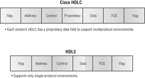
HDLC is the default encapsulation used by Cisco routers over synchronous serial links. Cisco’s HDLC is proprietary. It won’t communicate with any other vendor’s HDLC implementation—but then again, all HDLC implementations are proprietary. Figure 8-1 shows the Cisco HDLC format.
As shown in the figure, every vendor has a proprietary HDLC encapsulation method because each vendor has a different way for the HDLC protocol to encapsulate multiple Network layer protocols. If the vendors didn’t have a way for HDLC to communicate the different layer 3 protocols, then HDLC would only be able to carry one protocol. This proprietary header is placed in the data field of the HDLC encapsulation.
Figure 8-1: Cisco HDLC frame format
Configuring HDLC on Cisco Routers
Configuring HDLC encapsulation on an interface is really pretty straightforward. To configure it from the CLI, follow these simple router commands:
Router#config t
Enter configuration commands, one per line. End with CNTL/Z.
Router(config)#int s0
Router(config-if)#encapsulation hdlc
Router(config-if)#^Z
Router#
So, let’s say you have only one Cisco router, and you need to connect to a non-Cisco router because your other Cisco router is on order. What would you do? You couldn’t use the default HDLC serial encapsulation because it wouldn’t work. Instead, you would use something like PPP, an ISO-standard way of identifying the upper-layer protocols. You can check out RFC 1661 for more information on the origins and standards of PPP. Let’s discuss PPP in more detail and how to connect to routers using the PPP encapsulation.
Point-to-Point Protocol (PPP)
Let’s spend a little time on Point-to-Point Protocol (PPP). Remember that it’s a Data Link layer protocol that can be used over either asynchronous serial (dial-up) or synchronous serial (ISDN) media. It uses Link Control Protocol (LCP) to build and maintain data-link connections. Network Control Protocol (NCP) is used to allow multiple Network layer protocols (routed protocols) to be used on a point-to-point connection.
Figure 8-2 shows the protocol stack compared to the OSI reference model.
Figure 8-2: Point-to-Point Protocol stack
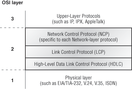
PPP contains the following four main components:
EIA/TIA-232-C, V.24, V.35, and ISDN A Physical layer international standard for serial communication.
HDLC A method for encapsulating datagrams over serial links.
LCP A method of establishing, configuring, maintaining, and terminating the point-to-point connection.
NCP A method of establishing and configuring different Network layer protocols. NCP is designed to allow the simultaneous use of multiple Network layer protocols. Some examples of protocols here are IPCP (Internet Protocol Control Protocol) and IPXCP (Internetwork Packet Exchange Control Protocol).
It is very important to note that the PPP Protocol stack is specified at the Physical and Data Link layers only. NCP is used to allow communication of multiple Network layer protocols by encapsulating the protocols across a PPP data link.

Remember that if you have a Cisco router and a non-Cisco router connected with a serial connection, you must configure PPP or another encapsulation method, such as Frame Relay, because the HDLC default just won’t work.
Configuring PPP on Cisco Routers
Configuring PPP encapsulation on an interface is the same as HDLC. To configure it from the CLI, follow these simple router commands:
Router#config t
Enter configuration commands, one per line. End with CNTL/Z.
Router(config)#int s0
Router(config-if)#encapsulation ppp
Router(config-if)#^Z
Router#
Exam Essentials
Remember the default serial encapsulation on Cisco routers. Cisco routers use a proprietary High-Level Data Link Control (HDLC) encapsulation on all their serial links by default.
Remember the PPP Data Link layer protocols. The three Data Link layer protocols are Network Control Protocol (NCP), which defines the Network layer protocols; Link Control Protocol (LCP), a method of establishing, configuring, maintaining, and terminating the point-to-point connection; and High-Level Data Link Control (HDLC), the MAC layer protocol that encapsulates the packets.
Configure and Verify Frame Relay on Cisco Routers
Frame Relay is still one of the most popular WAN services deployed over the past decade, and there’s a good reason for this—cost! It’s a rare network design or designer that has the privilege to ignore that all-important cost factor.
By default, Frame Relay is classified as a non-broadcast multi-access (NBMA) network, meaning it doesn’t send any broadcasts like RIP updates across the network.
Frame Relay Implementation and Monitoring
As I’ve said, there are a ton of Frame Relay commands and configuration options, but I’m going to zero in on the ones you really need to know when studying for the CCNA exam objectives. I’m going to start with one of the simplest configuration options: two routers with a single PVC between them. Next, I’ll show you a more complex configuration using subinterfaces, and I’ll demonstrate some of the monitoring commands available to verify the configuration.
Single Interface
Let’s get started by looking at a simple example. Say that I just want to connect two routers with a single PVC. Here’s how that configuration would look:
RouterA#config t
Enter configuration commands, one per line.  End with CNTL/Z.
RouterA(config)#int s0/0
RouterA(config-if)#encapsulation frame-relay
RouterA(config-if)#ip address 172.16.20.1 255.255.255.0
RouterA(config-if)#frame-relay lmi-type ansi
RouterA(config-if)#frame-relay interface-dlci 101
RouterA(config-if)#^Z
RouterA#
The first step is to specify the encapsulation as Frame Relay. There are two encapsulation types available: either Cisco or IETF. Notice that since I didn’t specify a particular encapsulation type the proprietary Cisco default type was used. If the other router were non-Cisco, I would’ve specified IETF. Next, I assigned an IP address to the interface, and then I specified a Link Management Interface (LMI) type. The LMI type is used between the local router and the Frame Relay switch. It can be set one of two ways, and your provider will indicate to you which to use. In this case, I set it to ANSI (the default being Cisco). Finally, I added the Data Link Connection Identifier (DLCI) of 101, which indicates the PVC I want to use (again, given to me by my ISP) and assumes that there’s only one PVC on this physical interface.
That’s all there is to it. If both sides are configured correctly, the circuit will come up.
Subinterfaces
As you learned earlier, you can have multiple virtual circuits on a single serial interface and yet treat each as a separate interface. You can make this happen by creating subinterfaces. Think of a subinterface as a logical interface defined by the IOS software. Several subinterfaces will share a single hardware interface, yet for configuration purposes, they operate as if they were separate physical interfaces, something known as multiplexing.
To configure a router in a Frame Relay network so that it will avoid split horizon issues by not permitting routing updates, just configure a separate subinterface for each PVC, with a unique DLCI and subnet assigned to the subinterface.
You define subinterfaces using a command like int s0.subinterface number. First, you have to set the encapsulation on the physical serial interface, and then you can define the subinterfaces—generally one subinterface per PVC. Here’s an example:
RouterA(config)#int s0
RouterA(config-if)#encapsulation frame-relay
RouterA(config-if)#int s0.?
  <0-4294967295>  Serial interface number
RouterA(config-if)#int s0.16 ?
  multipoint      Treat as a multipoint link
  point-to-point  Treat as a point-to-point link
RouterA(config-if)#int s0.16 point-to-point
Make sure you don’t have an IP address under the physical interface if you have configured subinterfaces.
You can define a serious amount of subinterfaces on any given physical interface, but keep in mind that there are only about 1,000 available DLCIs. In the preceding example, I chose to use subinterface 16 because that represents the DLCI number assigned to that PVC by the carrier. There are two types of subinterfaces:
Point-to-Point Used when a single virtual circuit connects one router to another. Each point-to-point subinterface requires its own subnet.
A point-to-point subinterface maps a single IP subnet per DLCI and addresses and resolves NBMA split horizon issues.
Multipoint This is when the router is the center of a star of virtual circuits that are using a single subnet for all routers’ serial interfaces connected to the frame switch. You’ll usually find this implemented with the hub router in this mode and the spoke routers in physical interface (always point-to-point) or point-to-point subinterface mode.
Monitoring Frame Relay
Several commands are used frequently to check the status of your interfaces and PVCs once you have Frame Relay encapsulation set up and running. To list them, use the show frame ? command like this:
RouterA>sho frame ?
end-to-end     Frame-relay end-to-end VC information
fragment       show frame relay fragmentation information
ip             show frame relay IP statistics
lapf           show frame relay lapf status/statistics
lmi            show frame relay lmi statistics
map            Frame-Relay map table
pvc            show frame relay pvc statistics
qos-autosense  show frame relay qos-autosense information
route          show frame relay route
svc            show frame relay SVC stuff
traffic        Frame-Relay protocol statistics
vofr           Show frame-relay VoFR statistics
The most common parameters that you view with the show frame-relay command are lmi, pvc, and map.
Now, let’s take a look at the most frequently used commands and the information they provide.
The show frame-relay lmi Command
The show frame-relay lmi command will give you the LMI traffic statistics exchanged between the local router and the Frame Relay switch. Here’s an example:
Router#sh frame lmi
LMI Statistics for interface Serial0 (Frame Relay DTE)
LMI TYPE = CISCO
  Invalid Unnumbered info 0     Invalid Prot Disc 0
  Invalid dummy Call Ref 0      Invalid Msg Type 0
  Invalid Status Message 0      Invalid Lock Shift 0
  Invalid Information ID 0      Invalid Report IE Len 0
  Invalid Report Request 0      Invalid Keep IE Len 0
  Num Status Enq. Sent 0        Num Status msgs Rcvd 0
  Num Update Status Rcvd 0      Num Status Timeouts 0
Router#
The router output from the show frame-relay lmi command displays any LMI errors, plus the LMI type.
The show frame pvc Command
The show frame pvc command will present you with a list of all configured PVCs and DLCI numbers. It provides the status of each PVC connection and traffic statistics too. It will also give you the number of BECN and FECN packets received on the router per PVC. (BECN and FECN are discussed in detail in the CCNA Cisco Certified Network Associate Study Guide, 7th Edition.)
Here is an example:
RouterA#sho frame pvc
PVC Statistics for interface Serial0 (Frame Relay DTE)
DLCI = 16,DLCI USAGE = LOCAL,PVC STATUS =ACTIVE,
INTERFACE = Serial0.1
 input pkts 50977876    output pkts 41822892
  in bytes 3137403144
 out bytes 3408047602   dropped pkts 5
  in FECN pkts 0
 in BECN pkts 0      out FECN pkts 0     out BECN pkts 0
 in DE pkts 9393     out DE pkts 0
 pvc create time 7w3d, last time pvc status changed 7w3d
DLCI = 18,DLCI USAGE =LOCAL,PVC STATUS =ACTIVE,
INTERFACE = Serial0.3
 input pkts 30572401   output pkts 31139837
  in bytes 1797291100
 out bytes 3227181474   dropped pkts 5
  in FECN pkts 0
 in BECN pkts 0      out FECN pkts 0     out BECN pkts 0
 in DE pkts 28      out DE pkts 0
 pvc create time 7w3d, last time pvc status changed 7w3d
If you only want to see information about PVC 16, you can type the command show frame-relay pvc 16.
The show interface Command
You can use the show interface command to check for LMI traffic. The show interface command displays information about the encapsulation, as well as layer 2 and layer 3 information. It also displays line, protocol, DLCI, and LMI information. Check it out:
RouterA#sho int s0
Serial0 is up, line protocol is up
 Hardware is HD64570
 MTU 1500 bytes, BW 1544 Kbit, DLY 20000 usec, rely
  255/255, load 2/255
 Encapsulation FRAME-RELAY, loopback not set, keepalive
  set (10 sec)
 LMI enq sent 451751,LMI stat recvd 451750,LMI upd recvd
  164,DTE LMI up
 LMI enq recvd 0, LMI stat sent 0, LMI upd sent 0
 LMI DLCI 1023 LMI type is CISCO frame relay DTE
 Broadcast queue 0/64, broadcasts sent/dropped 0/0,
  interface broadcasts 839294
The LMI DLCI in this code is used to define the type of LMI being used. If it happens to be 1023, it’s the default LMI type of Cisco. If LMI DLCI is zero, then it’s the ANSI LMI type (Q.933A uses 0 as well). If LMI DLCI is anything other than 0 or 1023, call your provider; they’ve got issues!
The show frame map Command
The show frame map command displays the Network layer–to–DLCI mappings. Here’s how that looks:
RouterB#show frame map
Serial0 (up): ipx 20.0007.7842.3575 dlci 16(0x10,0x400),
              dynamic, broadcast,, status defined, active
Serial0 (up): ip 172.16.20.1 dlci 16(0x10,0x400),
              dynamic, broadcast,, status defined, active
Serial1 (up): ipx 40.0007.7842.153a dlci 17(0x11,0x410),
              dynamic, broadcast,, status defined, active
Serial1 (up): ip 172.16.40.2 dlci 17(0x11,0x410),
              dynamic, broadcast,, status defined, active
Notice that the serial interfaces have two mappings—one for IP and one for IPX. Also important is that the Network layer addresses were resolved with the dynamic protocol Inverse ARP (IARP). After the DLCI number is listed, you can see some numbers in parentheses. The first one is 0x10, which is the hex equivalent for the DLCI number 16, used on serial 0. The 0x11 is the hex for DLCI 17 used on serial 1. The second numbers, 0x400 and 0x410, are the DLCI numbers configured in the Frame Relay frame. They’re different because of the way the bits are spread out in the frame.
The debug frame lmi Command
The debug frame lmi command will show output on the router consoles by default (as with any debug command). The information this command gives you will enable you to verify and troubleshoot the Frame Relay connection by helping you determine whether the router and switch are exchanging the correct LMI information. Here’s an example:
Router#debug frame-relay lmi
Serial3/1(in): Status, myseq 214
RT IE 1, length 1, type 0
KA IE 3, length 2, yourseq 214, myseq 214
PVC IE 0x7 , length 0x6 , dlci 130, status 0x2 , bw 0
Serial3/1(out): StEnq, myseq 215, yourseen 214, DTE up
datagramstart = 0x1959DF4, datagramsize = 13
FR encap = 0xFCF10309
00 75 01 01 01 03 02 D7 D6
Serial3/1(in): Status, myseq 215
RT IE 1, length 1, type 1
KA IE 3, length 2, yourseq 215, myseq 215
Serial3/1(out): StEnq, myseq 216, yourseen 215, DTE up
datagramstart = 0x1959DF4, datagramsize = 13
FR encap = 0xFCF10309
00 75 01 01 01 03 02 D8 D7
Exam Essentials
Understand what the LMI is in Frame Relay. The LMI is a signaling standard between a CPE device (router) and a frame switch. The LMI is responsible for managing and maintaining the status between these devices. This also provides transmission keepalives to ensure that the PVC does not shut down because of inactivity.
Understand the different Frame Relay encapsulations. Cisco uses two different Frame Relay encapsulation methods on their routers. Cisco is the default, and means that the router is connected to a Cisco Frame Relay switch; Internet Engineering Task Force (IETF) means that your router is connecting to anything except a Cisco Frame Relay switch.
Remember what the CIR is in Frame Relay. The CIR is the rate, in bits per second, at which the Frame Relay switch agrees to transfer data.
Configure a Frame Relay connection. The first step is to specify the encapsulation as Frame Relay. Next, assign an IP address to the interface. Next, specify an LMI type. Finally, add the Data Link Connection Identifier (DLCI).
Identify commands used to verify a Frame Relay connection. Use the show frame-relay lmi, show frame pvc, show interface, show frame map, and the debug frame lmi commands to verify the Frame Relay functionality.
Troubleshoot WAN Implementation Issues
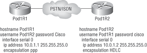
If you have a point-to-point link, but the encapsulations aren’t the same, the link will never come up. Figure 8-3 shows one link with PPP and one with HDLC.
Figure 8-3: Mismatched WAN encapsulations
Look at router Pod1R1 in this output:
Pod1R1#sh int s0/0
Serial0/0 is up, line protocol is down
  Hardware is PowerQUICC Serial
  Internet address is 10.0.1.1/24
  MTU 1500 bytes, BW 1544 Kbit, DLY 20000 usec,
     reliability 254/255, txload 1/255, rxload 1/255
  Encapsulation PPP, loopback not set
  Keepalive set (10 sec)
  LCP REQsent
Closed: IPCP, CDPCP
The serial interface is down, and LCP is sending requests but will never receive any responses because router Pod1R2 is using the HDLC encapsulation. To fix this problem, you would have to go to router Pod1R2 and configure the PPP encapsulation on the serial interface. There’s one more thing though—even though the usernames are configured and they’re wrong, it doesn’t matter because the command ppp authentication chap isn’t used under the serial interface configuration and the username command isn’t relevant in this example.
Always remember that you just can’t have PPP on one side and HDLC on the other. The two are incompatible.
Mismatched IP Addresses
A tricky problem to spot is if you have HDLC or PPP configured on your serial interface, but your IP addresses are wrong. Things seem to be just fine because the interfaces will show that they are up. For example, take a look at Figure 8-4, which shows two routers connected with different subnets: router Pod1R1 with 10.0.1.1/24 and router Pod1R2 with 10.2.1.2/24.
Figure 8-4: Mismatched IP addresses
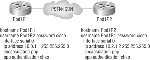
It should be obvious that this will never work, but take a look at the output:
Pod1R1#sh int s0/0
Serial0/0 is up, line protocol is up
  Hardware is PowerQUICC Serial
  Internet address is 10.0.1.1/24
  MTU 1500 bytes, BW 1544 Kbit, DLY 20000 usec,
     reliability 255/255, txload 1/255, rxload 1/255
  Encapsulation PPP, loopback not set
  Keepalive set (10 sec)
  LCP Open
  Open: IPCP, CDPCP
The IP addresses between the routers are wrong, but the link looks like it is working fine. This is because PPP, like HDLC and Frame Relay, is a layer 2 WAN encapsulation and doesn’t care about IP addresses at all. So, yes, the link is up, but you can’t use IP across this link because it is misconfigured.
To find and fix this problem, you can use the show running-config or the show interfaces command on each router, or you can use the show cdp neighbors detail command as follows:
Pod1R1#sh cdp neighbors detail
-------------------------
Device ID: Pod1R2
Entry address(es):
  IP address: 10.2.1.2
You can view and verify the directly connected neighbor’s IP address and then solve your problem.
Troubleshooting Frame Relay Networks
Troubleshooting Frame Relay networks isn’t any harder than troubleshooting any other type of network as long as you know what to look for. In this section, I’ll go over some basic problems that commonly occur in Frame Relay configuration and how to solve them.
First, I’ll discuss encapsulation. As you learned recently, there are two Frame Relay encapsulations: Cisco and IETF. Cisco is the default, and it means that you have a Cisco router on each end of the Frame Relay network. If you don’t have a Cisco router on the remote end of your Frame Relay network, then you need to run the IETF encapsulation as shown here:
RouterA(config)#int s0
RouterA(config-if)#encapsulation frame-relay ?
  ietf  Use RFC1490 encapsulation
  <cr>
RouterA(config-if)#encapsulation frame-relay ietf
Once you verify that you’re using the correct encapsulation, you then need to check out your Frame Relay mappings. For example, take a look at Figure 8-5.
Figure 8-5: Frame Relay mappings
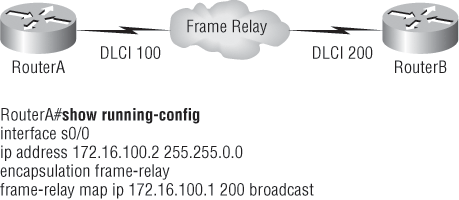
So, why can’t RouterA talk to RouterB across the Frame Relay network? If you take a close look at the frame-relay map statement, you will see that the DLCI mappings are incorrect. You cannot use a remote DLCI to communicate to the Frame Relay switch; you must use your DLCI number. The mapping should have included DLCI 100 instead of DLCI 200.
Now that you know how to ensure that you have the correct Frame Relay encapsulation, and that DLCIs are only locally significant, let’s look into some routing protocol problems typically associated with Frame Relay. See if you can find a problem with the two configurations in Figure 8-6.
Figure 8-6: Frame Relay routing problems
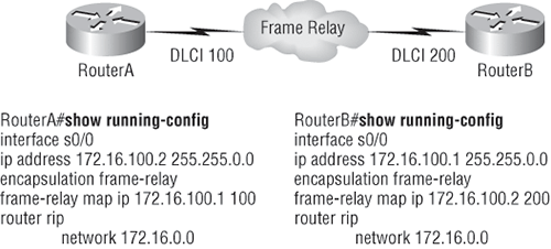
The configuration appears to be correct, but remember that Frame Relay is a NBMA network by default, meaning that it doesn’t send any broadcasts across the PVC. So, because the mapping statements do not have the broadcast argument at the end of the line, broadcasts, like RIP updates, won’t be sent across the PVC.
Exam Essentials
Remember the two Frame Relay encapsulation methods. There are two Frame Relay encapsulations: Cisco and IETF. Cisco is the default, and it means that you have a Cisco router on each end of the Frame Relay network. If you don’t have a Cisco router on the remote end of your Frame Relay network, then you need to run the IETF encapsulation.
Remember that DLCI numbers are considered locally significant. You cannot use a remote DLCI to communicate to the Frame Relay switch—you must use your DLCI number.
Identify commands used to troubleshoot Frame Relay problems, including IP address mismatch, encapsulation mismatch, and LMI mismatch. Use the show interface, show cdp neighbors detail, and the show frame relay map commands to troubleshoot IP address mismatches, encapsulation mismatches, and LMI mismatches.
Describe VPN Technology (Including Importance, Benefits, Role, Impact, and Components)
A virtual private network (VPN) allows the creation of private networks across the Internet, enabling privacy and tunneling of non-TCP/IP protocols. VPNs are used daily to give remote users and disjointed networks connectivity over a public medium like the Internet instead of using more expensive permanent means.
Types of VPNs are named based on the role they play in a business. There are three different categories of VPNs:
Remote Access VPNs Remote access VPNs allow remote users like telecommuters to securely access the corporate network wherever and whenever needed.
Site-to-Site VPNs Site-to-site VPNs, or intranet VPNs, allow a company to connect its remote sites to the corporate backbone securely over a public medium like the Internet instead of requiring more expensive WAN connections like Frame Relay.
Extranet VPNs Extranet VPNs allow an organization’s suppliers, partners, and customers to be connected to the corporate network in a limited way for business-to-business (B2B) communications.
There are two ways to create a VPN. The first approach uses IPSec to create authentication and encryption services between endpoints on an IP network. The second approach is via tunneling protocols, allowing you to establish a tunnel between endpoints on a network. Understand that the tunnel itself is a means for data or protocols to be encapsulated inside another protocol.
Here are some brief descriptions of the most common tunneling protocols:
Layer 2 Forwarding (L2F) Layer 2 Forwarding (L2F) is a Cisco-proprietary tunneling protocol, and it was their first tunneling protocol created for virtual private dial-up networks (VPDNs). VPDN allows a device to use a dial-up connection to create a secure connection to a corporate network. L2F was later replaced by L2TP, which is backward compatible with L2F.
Point-to-Point Tunneling Protocol (PPTP) Point-to-Point Tunneling Protocol (PPTP) was created by Microsoft to allow the secure transfer of data from remote networks to the corporate network.
Layer 2 Tunneling Protocol (L2TP) Layer 2 Tunneling Protocol (L2TP) was created by Cisco and Microsoft to replace L2F and PPTP. L2TP merged the capabilities of both L2F and PPTP into one tunneling protocol.
Generic Routing Encapsulation (GRE) Generic Routing Encapsulation (GRE) is another Cisco-proprietary tunneling protocol. It forms virtual point-to-point links, allowing a variety of protocols to be encapsulated in IP tunnels.
Exam Essentials
Understand the term virtual private network (VPN). A virtual private network (VPN) allows the creation of private networks across the Internet, enabling privacy and tunneling of non-TCP/IP protocols. VPNs are used daily to give remote users and disjointed networks connectivity over a public medium, such as the Internet, instead of using more expensive permanent means.
Remember the three categories of VPNs. Types of VPNs are named based on the roles they play in business. There are three different categories of VPNs: remote access VPNs, site-to-site VPNs, and extranet VPNs.
Identify tunneling protocols. The tunneling protocols available for VPNs are Layer 2 Forwarding (L2F), Point-to-Point Tunneling Protocol (PPTP), Layer 2 Tunneling Protocol (L2TP), and Generic Routing Encapsulation (GRE).
Configure and Verify a PPP Connection between Cisco Routers
After you configure your serial interface to support PPP encapsulation, you can configure authentication using PPP between routers. First, you need to set the hostname of the router, if it’s not already set. Then you need to set the username and password for the remote router that will be connecting to your router.
Here’s an example:
Router#config t
Enter configuration commands, one per line. End with CNTL/Z.
Router(config)#hostname RouterA
RouterA(config)#username RouterB password cisco
When using the hostname command, remember that the username is the hostname of the remote router that’s connecting to your router. Don’t forget that it’s case sensitive. Also, the password on both routers must be the same. It’s a plaintext password that you can see with a show run command; you can encrypt the password by using the command service password-encryption. You must have a username and password configured for each remote system to which you plan to connect. The remote routers must also be configured with usernames and passwords.
After you set the hostname, usernames, and passwords, set the username and password for the remote router that will be connecting to your router; choose the authentication type, either CHAP or PAP (discussed in detail in the CCNA Cisco Certified Network Associate Study Guide, 7th Edition):
RouterA#config t
Enter configuration commands, one per line. End with CNTL/Z.
RouterA(config)#int s0
RouterA(config-if)#ppp authentication chap pap
RouterA(config-if)#^Z
RouterA#
If both methods are configured on the same line, as shown here, only the first method will be used during link negotiation. The second method acts as a backup just in case the first method fails.
Verifying PPP Encapsulation
Now that PPP encapsulation is enabled, I’ll show you how to verify that it’s up and running. First, let’s take a look at a figure of a sample network. Figure 8-7 shows two routers connected with either a point-to-point serial or ISDN connection.
Figure 8-7: PPP authentication
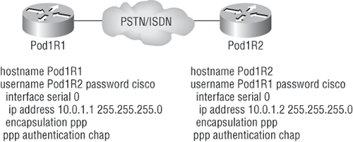
You can start verifying the configuration with the show interface command as follows:
Pod1R1#sh int s0/0
Serial0/0 is up, line protocol is up
  Hardware is PowerQUICC Serial
  Internet address is 10.0.1.1/24
  MTU 1500 bytes, BW 1544 Kbit, DLY 20000 usec,
     reliability 239/255, txload 1/255, rxload 1/255
  Encapsulation PPP
  loopback not set
  Keepalive set (10 sec)
  LCP Open
  Open: IPCP, CDPCP
[output cut]
Notice that the sixth line lists encapsulation as PPP, and the ninth line shows that the LCP is open. This means that it has negotiated the session establishment and all is well. The 10th line indicates that NCP is listening for the protocols IP and CDP.
Let’s look at an example of an incorrect configuration and determine the problem. Look at the configuration shown in Figure 8-8.
Figure 8-8: Failed PPP authentication
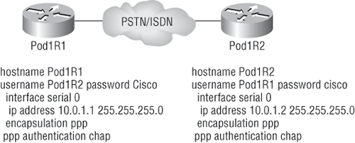
The C is capitalized on the Pod1R2 username command found in the configuration of router Pod1R1. This is wrong because the usernames and passwords are case sensitive. Let’s take a look at the show interface command and see what happens:
Pod1R1#sh int s0/0
Serial0/0 is up, line protocol is down
  Hardware is PowerQUICC Serial
  Internet address is 10.0.1.1/24
  MTU 1500 bytes, BW 1544 Kbit, DLY 20000 usec,
     reliability 243/255, txload 1/255, rxload 1/255
  Encapsulation PPP, loopback not set
  Keepalive set (10 sec)
  LCP Closed
  Closed: IPCP, CDPCP
First, notice in the first line of output that Serial0/0 is up, line protocol is down. This is because there are no keepalives coming from the remote router. Next, notice that the LCP is closed because the authentication failed.
Debugging PPP Authentication
To display the CHAP authentication process as it occurs between two routers in the network, just use the command debug ppp authentication.
If your PPP encapsulation and authentication are set up correctly on both routers, and your usernames and passwords are all good, the debug ppp authentication command will display output that looks like this:
d16h: Se0/0 PPP: Using default call direction
1d16h: Se0/0 PPP: Treating connection as a dedicated line
1d16h: Se0/0 CHAP: O CHALLENGE id 219 len 27 from "Pod1R1"
1d16h: Se0/0 CHAP: I CHALLENGE id 208 len 27 from "Pod1R2"
1d16h: Se0/0 CHAP: O RESPONSE id 208 len 27 from "Pod1R1"
1d16h: Se0/0 CHAP: I RESPONSE id 219 len 27 from "Pod1R2"
1d16h: Se0/0 CHAP: O SUCCESS id 219 len 4
1d16h: Se0/0 CHAP: I SUCCESS id 208 len 4
If you have the username wrong, as in the PPP authentication failure example in Figure 8-8, the output would look something like this:
1d16h: Se0/0 PPP: Using default call direction
1d16h: Se0/0 PPP: Treating connection as a dedicated line
1d16h: %SYS-5-CONFIG_I: Configured from console by console
1d16h: Se0/0 CHAP: O CHALLENGE id 220 len 27 from "Pod1R1"
1d16h: Se0/0 CHAP: I CHALLENGE id 209 len 27 from "Pod1R2"
1d16h: Se0/0 CHAP: O RESPONSE id 209 len 27 from "Pod1R1"
1d16h: Se0/0 CHAP: I RESPONSE id 220 len 27 from "Pod1R2"
1d16h: Se0/0 CHAP: O FAILURE id 220 len 25 msg is "MD/DES compare failed"
PPP with CHAP authentication is a three-way authentication, and if the usernames and passwords are not configured exactly the way they should be, the authentication will fail and the link will be down.
Exam Essentials
Configure and verify a PPP connection. To configure a PPP connection, set the hostname of the router, set the username and password for the remote router that will be connecting to your router, and choose the authentication type, either CHAP or PAP. To verify, use the show interfaces and the debug ppp authentication commands.
1. Which command will display the CHAP authentication process as it occurs between two routers in the network?
A. show chap authentication
B. show interface serial 0
C. debug ppp authentication
D. debug chap authentication
2. Suppose that you have a customer who has a central headquarters (HQ) and six branch offices. They anticipate adding six more branches in the near future. They want to implement a WAN technology that will allow the branches to economically connect to HQ, and you have no free ports on the HQ router. Which of the following would you recommend?
A. PPP
B. HDLC
C. Frame Relay
D. ISDN
3. How should a router that is being used in a Frame Relay network be configured to keep split horizon issues from preventing routing updates?
A. Configure a separate subinterface for each PVC with a unique DLCI and subnet assigned to the subinterface.
B. Configure each Frame Relay circuit as a point-to-point line to support multicast and broadcast traffic.
C. Configure many subinterfaces in the same subnet.
D. Configure a single subinterface to establish multiple PVC connections to multiple remote router interfaces.
4. Which encapsulations can be configured on a serial interface? (Choose three.)
A. Ethernet
B. Token Ring
C. HDLC
D. Frame Relay
E. PPP
5. The Acme Corporation is implementing dial-up services to enable remote-office employees to connect to the local network. The company uses multiple routed protocols, needs authentication of users connecting to the network, and because some calls will be long distance, needs callback support. Which of the following protocols is the best choice for these remote services?
A. 802.1
B. Frame Relay
C. HDLC
D. PPP
E. PAP
6. Which WAN encapsulations can be configured on an asynchronous serial connection? (Choose two.)
A. PPP
B. ATM
C. HDLC
D. SDLC
E. Frame Relay
7. Using the following output of the show interfaces command as a reference, why won’t the serial link between the Corp router and the Remote router come up?
Corp#sh int s0/0
Serial0/0 is up, line protocol is down
  Hardware is PowerQUICC Serial
  Internet address is 10.0.1.1/24
  MTU 1500 bytes, BW 1544 Kbit, DLY 20000 usec,
     reliability 254/255, txload 1/255, rxload 1/255
  Encapsulation PPP, loopback not set
Remote#sh int s0/0
Serial0/0 is up, line protocol is down
  Hardware is PowerQUICC Serial
  Internet address is 10.0.1.2/24
  MTU 1500 bytes, BW 1544 Kbit, DLY 20000 usec,
     reliability 254/255, txload 1/255, rxload 1/255
  Encapsulation HDLC, loopback not set
A. The serial cable is faulty.
B. The IP addresses are not in the same subnet.
C. The subnet masks are not correct.
D. The keepalive settings are not correct.
E. The layer 2 frame types are not compatible.
8. A remote site has just been connected to the central office. However, remote users cannot access applications at the central office. The remote router can be pinged from the central office router. After reviewing the command output shown below, which do you think is the most likely reason for the problem?
Central#show running-config
!
interface Serial0
 ip address 10.0.8.1 255.255.248.0
 encapsulation frame-relay
 frame-relay map ip 10.0.15.2 200
!
Router rip
Network 10.0.0.0
Remote#show running-config
!
interface Serial0
 ip address 10.0.15.2 255.255.248.0
 encapsulation frame-relay
 frame-relay map ip 10.0.8.1 100
!
Router rip
Network 10.0.0.0
A. The Frame Relay PVC is down.
B. The IP addressing on the Central/Remote router link is incorrect.
C. RIP routing information is not being forwarded.
D. Frame Relay Inverse ARP is not properly configured.
9. Which of the following describes an industry-wide standard suite of protocols and algorithms that allows for secure data transmission over an IP-based network that functions at the layer 3 Network layer of the OSI model?
A. HDLC
B. Cable
C. VPN
D. IPSec
E. xDSL
10. Which of the following describes the creation of private networks across the Internet, enabling privacy and tunneling of non-TCP/IP protocols?
A. HDLC
B. Cable
C. VPN
D. IPSec
E. xDSL
1. C. The command debug ppp authentication will show you the authentication process that PPP uses between point-to-point connections.
2. C. The key is “there are no free ports” on your router. Only Frame Relay can provide a connection to multiple locations with one interface in an economical manner.
3. A. If you have a serial port configured with multiple DLCIs connected to multiple remote sites, split horizon rules stop route updates received on an interface from being sent out the same interface. By creating subinterfaces for each PVC, you can avoid the split horizon issues when using Frame Relay.
4. C, D, E. Ethernet and Token Ring are LAN technologies and cannot be configured on a serial interface. PPP, HDLC, and Frame Relay are layer 2 WAN technologies that are typically configured on a serial interface.
5. D. PPP is your only option, as HDLC and Frame Relay do not support these types of business requirements. PPP provides dynamic addressing, authentication using PAP or CHAP, and callback services.
6. A, B. Although it is a correct answer, we have not discussed ATM because it is not covered in depth on the CCNA exam. PPP is used mostly for dial-up (async) services, but ATM could be used as well, although it typically is not used anymore because PPP is so efficient.
7. E. This is an easy question because the Remote router is using the default HDLC serial encapsulation and the Corp router is using the PPP serial encapsulation. You should go to the Remote router and set that encapsulation to PPP or change the Corp router back to the default of HDLC.
8. C. Even though the IP addresses don’t look correct, they are in the same subnet, so answer B is not correct. The question states that you can ping the other side, so the PVC must be up; therefore, answer A can’t be correct. You cannot configure IARP, so only answer C can be correct. Because a Frame Relay network is a non-broadcast multi-access network by default, broadcasts such as RIP updates cannot be sent across the PVC unless you use the broadcast statement at the end of the frame-relay map command.
9. D. IPSec is an industry-wide standard suite of protocols and algorithms that allows for secure data transmission over an IP-based network that functions at the layer 3 Network layer of the OSI model.
10. C. A virtual private network (VPN) allows the creation of private networks across the Internet, enabling privacy and tunneling of non-TCP/IP protocols. A VPN can be set up across any type of link.
