Chapter 17. Cisco Software-Defined Access (SDA)
This chapter covers the following exam topics:
1.0 Network Fundamentals
1.1 Explain the role and function of network components
1.1.e Controllers (Cisco DNA Center and WLC)
6.0 Automation and Programmability
6.1 Explain how automation impacts network management
6.2 Compare traditional networks with controller-based networking
6.3 Describe controller-based and software defined architectures (overlay, underlay, and fabric)
6.3.a Separation of control plane and data plane
6.3.b Northbound and southbound APIs
6.4 Compare traditional campus device management with Cisco DNA Center enabled device management
Cisco Software-Defined Access (SDA) uses a software defined networking approach to build a converged wired and wireless campus LAN. The word access in the name refers to the endpoint devices that access the network, while software-defined refers to many of the usual software-defined architectural features discussed in Chapter 16, “Introduction to Controller-Based Networking.” Those features include a centralized controller—DNA Center—with southbound and northbound protocols. It also includes a completely different operational model inside SDA, with a network fabric composed of an underlay network and an overlay network.
SDA fills the position as Cisco’s campus offering within Cisco Digital Network Architecture (DNA). Cisco DNA defines the entire architecture for the new world of software defined networks, digitization, and Cisco’s reimagining of how networks should be operated in the future. This chapter introduces SDA, which exists as one implementation of Cisco DNA.
The discussion of SDA and DNA provides a great backdrop to discuss a few other topics from the CCNA blueprint: the DNA Center controller and network management. SDA uses the DNA Center controller to configure and operate SDA. However, DNA Center also acts as a complete network management platform. To understand DNA Center, you also need to understand traditional network management as well as the new management models using controllers.
“Do I Know This Already?” Quiz
Take the quiz (either here or use the PTP software) if you want to use the score to help you decide how much time to spend on this chapter. The letter answers are listed at the bottom of the page following the quiz. Appendix C, found both at the end of the book as well as on the companion website, includes both the answers and explanations. You can also find both answers and explanations in the PTP testing software.
Table 17-1 “Do I Know This Already?” Foundation Topics Section-to-Question Mapping
Foundation Topics Section |
Questions |
SDA Fabric, Underlay, and Overlay |
1–3 |
DNA Center and SDA Operation |
4, 5 |
DNA Center as a Network Management Platform |
6 |
1. In Cisco Software-Defined Access (SDA), which term refers to the devices and cabling, along with configuration that allows the network device nodes enough IP connectivity to send IP packets to each other?
Fabric
Overlay
Underlay
VXLAN
2. In Cisco Software-Defined Access (SDA), which term refers to the functions that deliver endpoint packets across the network using tunnels between the ingress and egress fabric nodes?
Fabric
Overlay
Underlay
VXLAN
3. In Software-Defined Access (SDA), which of the answers are part of the overlay data plane?
LISP
GRE
OSPF
VXLAN
4. Which answers best describe options of how to implement security with scalable groups using DNA Center and SDA? (Choose two answers.)
A human user from the DNA Center GUI
An automation application using NETCONF
A human user using the CLI of an SDA fabric edge node
An automation application using REST
5. Which of the following protocols or tools could be used as part of the Cisco DNA Center southbound interface? (Choose three answers.)
Ansible
SSH
NETCONF
SNMP
Puppet
6. Which of the following are network management features performed by both traditional network management software as well as by DNA Center? (Choose two answers.)
Network device discovery
Software-Defined Access configuration
End-to-end path discovery with ACL analysis
Device installation (day 0), configuration (day 1), and monitoring (day n) operations
Answers to the “Do I Know This Already?” quiz:
1 C
2 B
3 D
4 A, D
5 B, C, D
6 A, D
Foundation Topics
SDA Fabric, Underlay, and Overlay
Cisco Software-Defined Access (SDA) creates an entirely new way to build campus LANs as compared with the traditional methods of networking discussed in most chapters of this book. In the mid 2010s, Cisco set about to reimagine campus networking, with SDA as the result.
SDA uses the software-defined architectural model introduced in Chapter 16, with a controller and various APIs. It still uses a physical network with switches and routers, cables, and various endpoints. At the center sits the Digital Network Architecture (DNA) Center controller, as shown in Figure 17-1, with human users making use of a graphical user interface (GUI) and automation using APIs. In short, DNA Center is the controller for SDA networks.
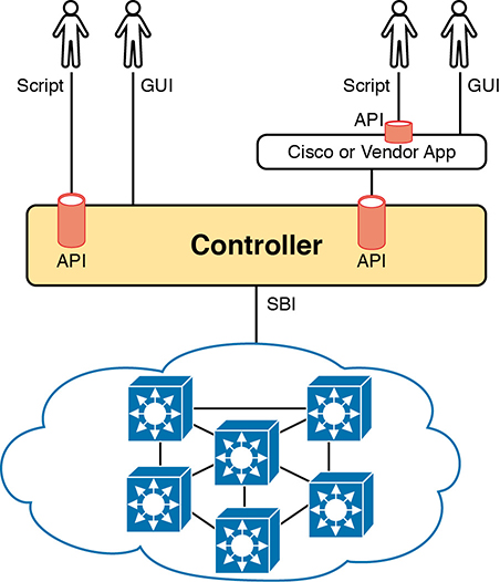
Figure 17-1 SDA Architectural Model with DNA Center
Architecturally, the southbound side of the controller contains the fabric, underlay, and overlay. By design in SDN implementations, most of the interesting new capabilities occur on the northbound side, which are examined in the second half of this chapter. This first half of the chapter examines the details south of the controller—namely, the fabric, underlay network, and overlay network.
Overlay: The mechanisms to create VXLAN tunnels between SDA switches, which are then used to transport traffic from one fabric endpoint to another over the fabric.
Underlay: The network of devices and connections (cables and wireless) to provide IP connectivity to all nodes in the fabric, with a goal to support the dynamic discovery of all SDA devices and endpoints as a part of the process to create overlay VXLAN tunnels.
Fabric: The combination of overlay and underlay, which together provide all features to deliver data across the network with the desired features and attributes.
In less formal terms, the underlay exists as multilayer switches and their links, with IP connectivity—but for a special purpose. The underlay supports some new concepts with a tunneling method called VXLAN. Traffic sent by the endpoint devices flows through VXLAN tunnels in the overlay—a completely different process than traditional LAN switching and IP routing.
For instance, think about the idea of sending packets from hosts on the left of a network, over SDA, to hosts on the right. For instance, imagine a packet enters on the left side of the physical network at the bottom of Figure 17-2 and eventually exits the campus out switch SW2 on the far right. This underlay network looks like a more traditional network drawing, with several devices and links.
The overlay drawing at the top of the figure shows only two switches—called fabric edge nodes, because they happen to be at the edges of the SDA fabric—with a tunnel labeled VXLAN connecting the two. Both concepts (underlay and overlay) together create the SDA fabric.
The next few pages explain both the underlay and overlay in a little more depth.

Figure 17-2 Fabric, Underlay, and Overlay Concepts
The SDA Underlay
With SDA, the underlay exists to provide connectivity between the nodes in the SDA environment for the purpose of supporting VXLAN tunnels in the overlay network. To do that, the underlay includes the switches, routers, cables, and wireless links used to create the physical network. It also includes the configuration and operation of the underlay so it can support the work of the overlay network.
Using Existing Gear for the SDA Underlay
To build an SDA underlay network, companies have two basic choices. They can use their existing campus network and add new configuration to create an underlay network, while still supporting their existing production traffic with traditional routing and switching. Alternately, the company can purchase some new switches and build the SDA network without concern for harming existing traffic, and migrate endpoints to the new SDA network over time.
To build SDA into an existing network, it helps to think for a moment about some typical campus network designs. The larger campus site may use either a two-tier or three-tier design as discussed in Chapter 13, “LAN Architecture.” It has a cluster of wireless LAN controllers (WLCs) to support a number of lightweight APs (LWAPs). Engineers have configured VLANs, VLAN trunks, IP routing, IP routing protocols, ACLs, and so on. And the LAN connects to WAN routers.
SDA can be added into an existing campus LAN, but doing so has some risks and restrictions. First and foremost, you have to be careful not to disrupt the current network while adding the new SDA features to the network. The issues include
Because of the possibility of harming the existing production configuration, DNA Center should not be used to configure the underlay if the devices are currently used in production. (DNA Center will be used to configure the underlay with deployments that use all new hardware.)
The existing hardware must be from the SDA compatibility list, with different models supported depending on their different SDA roles (see a link at www.cisco.com/go/sda).
The device software levels must meet the requirements, based on their roles, as detailed in that same compatibility list.
For instance, imagine an enterprise happened to have an existing campus network that uses SDA-compatible hardware. That company might need to update the IOS versions in a few cases. Additionally, the engineers would need to configure the underlay part of the SDA devices manually rather than with DNA Center because Cisco assumes that the existing network already supports production traffic, so they want the customer directly involved in making those changes.
The SDA underlay configuration requires you to think about and choose the different SDA roles filled by each device before you can decide which devices to use and which minimum software levels each requires. If you look for the hardware compatibility list linked from www.cisco.com/go/sda, you will see different lists of supported hardware and software depending on the roles. These roles include
Fabric edge node: A switch that connects to endpoint devices (similar to traditional access switches)
Fabric border node: A switch that connects to devices outside SDA’s control, for example, switches that connect to the WAN routers or to an ACI data center
Fabric control node: A switch that performs special control plane functions for the underlay (LISP), requiring more CPU and memory
For example, when I was writing this chapter back in 2019, Cisco’s compatibility list included many Catalyst 9300, 9400, and 9500 switches, but also some smaller Catalyst 3850 and 3650 switches, as fabric edge nodes. However, the Catalyst 2960X or 2960XR products did not make the list as fabric edge nodes. For fabric control nodes, the list included more higher-end Catalyst switch models (which typically have more CPU and RAM), plus several router models (routers typically have much more RAM for control plane protocol storage—for instance, for routing protocols).
The beginning of an SDA project will require you to look at the existing hardware and software to begin to decide whether the existing campus might be a good candidate to build the fabric with existing gear or to upgrade hardware when building the new campus LAN.
Using New Gear for the SDA Underlay
When buying new hardware for the SDA fabric—that is, a greenfield design—you remove many of the challenges that exist when deploying SDA on existing gear. You can simply order compatible hardware and software. Once it arrives, DNA Center can then configure all the underlay features automatically.
At the same time, the usual campus LAN design decisions still need to be made. Enterprises use SDA as a better way to build and operate a campus network, but SDA is still a campus network. It needs to provide access and connectivity to all types of user devices. When planning a greenfield SDA design, plan to use SDA-compatible hardware, but also think about these traditional LAN design points:
The number of ports needed in switches in each wiring closet
The port speeds required
The benefit of a switch stack in each wiring closet
The cable length and types of cabling already installed
The need for power (PoE/PoE+)
The power available in each new switch versus the PoE power requirements
Link capacity (speed and number of links) for links between switches
As far as the topology, traditional campus design does tell us how to connect devices, but SDA does not have to follow those traditional rules. To review, traditional campus LAN Layer 2 design (as discussed back in Chapter 13) tells us to connect each access switch to two different distribution layer switches, but not to other access layer switches, as shown in Figure 17-3. The access layer switch acts as a Layer 2 switch, with a VLAN limited to those three switches.

Figure 17-3 Traditional Access Layer Design: Three Switches in STP Triangle
Take a moment to reflect about the traditional features shown in the figure. The distribution layer switches—Layer 3 switches—act as the default gateway used by hosts and often implement HSRP for better availability. The design uses more than one uplink from the access to distribution layer switches, with Layer 2 EtherChannels, to allow balancing in addition to redundancy. And STP/RSTP manages the small amount of Layer 2 redundancy in the campus, preventing loops by blocking on some ports.
In comparison, a greenfield SDA fabric uses a routed access layer design. Routed access layer designs have been around long before SDA, but SDA makes good use of the design, and it works very well for the underlay with its goal to support VXLAN tunnels in the overlay network. A routed access layer design simply means that all the LAN switches are Layer 3 switches, with routing enabled, so all the links between switches operate as Layer 3 links.
With a greenfield SDA deployment—that is, all new gear that you can allow to be configured by DNA Center—DNA Center will configure the devices’ underlay configuration to use a routed access layer. Because DNA Center knows it can configure the switches without concern of harming a production network, it chooses the best underlay configuration to support SDA. That best configuration happens to use a design called a routed access layer design, which has these features:
All switches act as Layer 3 switches.
The switches use the IS-IS routing protocol.
All links between switches (single links, EtherChannels) are routed Layer 3 links (not Layer 2 links).
As a result, STP/RSTP is not needed, with the routing protocol instead choosing which links to use based on the IP routing tables.
The equivalent of a traditional access layer switch—an SDA edge node—acts as the default gateway for the endpoint devices, rather than distribution switches.
As a result, HSRP (or any FHRP) is no longer needed.
Figure 17-4 repeats the same physical design as in Figure 17-3 but shows the different features with the routed access design as configured using DNA Center.
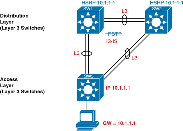
Figure 17-4 SDA Fabric Layer 3 Access Benefits
The SDA Overlay
When you first think of the SDA overlay, think of this kind of sequence. First, an endpoint sends a frame that will be delivered across the SDA network. The first SDA node to receive the frame encapsulates the frame in a new message—using a tunneling specification called VXLAN—and forwards the frame into the fabric. Once the ingress node has encapsulated the original frame in VXLAN, the other SDA nodes forward the frame based on the VXLAN tunnel details. The last SDA node removes the VXLAN details, leaving the original frame, and forwards the original frame on toward the destination endpoint.
While the summary of some of SDA’s overlay work in the previous paragraph may sound like a lot of work, all that work happens in each switch’s ASIC. So, while it is more complex to understand, there is no performance penalty for the switches to perform the extra work.
When Cisco set about to create SDA, they saw an opportunity. Making use of VXLAN tunnels opened up the possibilities for a number of new networking features that did not exist without VXLAN. This next topic begins with a closer look at the VXLAN tunnels in the overlay, followed by a discussion of how SDA uses LISP for endpoint discovery and location needed to create the VXLAN tunnels.
VXLAN Tunnels in the Overlay (Data Plane)
SDA has many additional needs beyond the simple message delivery—needs that let it provide improved functions. To that end, SDA does not only route IP packets or switch Ethernet frames. Instead, it encapsulates incoming data link frames in a tunneling technology for delivery across the SDA network, with these goals in mind:
The VXLAN tunneling (the encapsulation and de-encapsulation) must be performed by the ASIC on each switch so that there is no performance penalty. (That is one reason for the SDA hardware compatibility list: the switches must have ASICs that can perform the work.)
The VXLAN encapsulation must supply header fields that SDA needs for its features, so the tunneling protocol should be flexible and extensible, while still being supported by the switch ASICs.
The tunneling encapsulation needs to encapsulate the entire data link frame instead of encapsulating the IP packet. That allows SDA to support Layer 2 forwarding features as well as Layer 3 forwarding features.
To achieve those goals, when creating SDA, Cisco chose the Virtual Extensible LAN (VXLAN) protocol to create the tunnels used by SDA. When an SDA endpoint (for example, an end-user computer) sends a data link frame into an SDA edge node, the ingress edge node encapsulates the frame and sends it across a VXLAN tunnel to the egress edge node, as shown in Figure 17-5.
To support the VXLAN encapsulation, the underlay uses a separate IP address space as compared with the rest of the enterprise, including the endpoint devices that send data over the SDA network. The overlay tunnels use addresses from the enterprise address space. For instance, imagine an enterprise used these address spaces:
10.0.0.0/8: Entire enterprise
172.16.0.0/16: SDA underlay
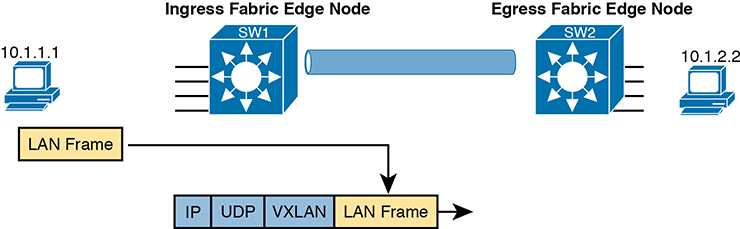
Figure 17-5 Fundamentals of VXLAN Encapsulation in SDA
To make that work, first the underlay would be built using the 172.16.0.0/16 IPv4 address space, with all links using addresses from that address space. As an example, Figure 17-6 shows a small SDA design, with four switches, each with one underlay IP address shown (from the 172.16.0.0/16 address space).
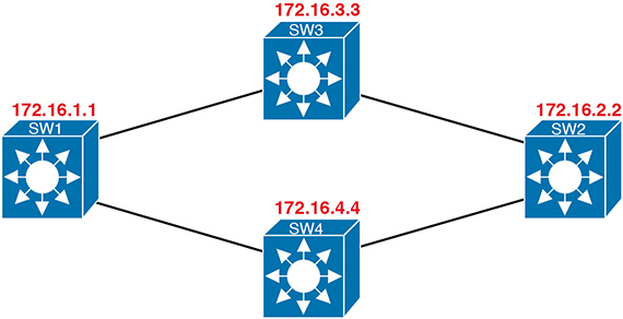
Figure 17-6 SDA Underlay Using 172.16.0.0
The overlay tunnel creates a path between two fabric edge nodes in the overlay IP address space—that is, in the same address space used by all the endpoints in the enterprise. Figure 17-7 emphasizes that point by showing the endpoints (PCs) on the left and right, with IP addresses in network 10.0.0.0/8, with the VXLAN overlay tunnel shown with addresses also from 10.0.0.0/8.
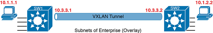
Figure 17-7 VXLAN Tunnel and Endpoints with IPv4 Addresses in the Same IPv4 Space
LISP for Overlay Discovery and Location (Control Plane)
Ignore SDA for a moment, and think about traditional Layer 2 switching and Layer 3 routing. How do their control planes work? In other words, how do these devices discover the possible destinations in the network, store those destinations, so that the data plane has all the data it needs when making a forwarding decision? To summarize:
Traditional Layer 2 switches learn possible destinations by examining the source MAC addresses of incoming frames, storing those MAC addresses as possible future destinations in the switch’s MAC address table. When new frames arrive, the Layer 2 switch data plane then attempts to match the Ethernet frame’s destination MAC address to an entry in its MAC address table.
Traditional Layer 3 routers learn destination IP subnets using routing protocols, storing routes to reach each subnet in their routing tables. When new packets arrive, the Layer 3 data plane attempts to match the IP packet’s destination IP address to some entry in the IP routing table.
Nodes in the SDA network do not do these same control plane actions to support endpoint traffic. Just to provide a glimpse into the process for the purposes of CCNA, consider this sequence, which describes one scenario:
Fabric edge nodes—SDA nodes that connect to the edge of the SDA fabric—learn the location of possible endpoints using traditional means, based on their MAC address, individual IP address, and by subnet, identifying each endpoint with an endpoint identifier (EID).
The fabric edge nodes register the fact that the node can reach a given endpoint (EID) into a database called the LISP map server.
The LISP map server keeps the list of endpoint identifiers (EIDs) and matching routing locators (RLOCs) (which identify the fabric edge node that can reach the EID).
In the future, when the fabric data plane needs to forward a message, it will look for and find the destination in the LISP map server’s database.
For instance, switches SW3 and SW4 in Figure 17-8 each just learned about different subnets external to the SDA fabric. As noted at step 1 in the figure, switch SW3 sent a message to the LISP map server, registering the information about subnet 10.1.3.0/24 (an EID), with its RLOC setting to identify itself as the node that can reach that subnet. Step 2 shows an equivalent registration process, this time for SW4, with EID 10.1.4.0/24, and with R4’s RLOC of 172.16.4.4. Note that the table at the bottom of the figure represents that data held by the LISP map server.
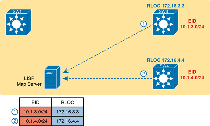
Figure 17-8 Edge Nodes Register IPv4 Prefixes (Endpoint IDs) with LISP Map Server
When new incoming frames arrive, the ingress tunnel router (ITR)—the SDA node that receives the new frame from outside the SDA fabric—needs some help from the control plane. To where should the ITR forward this frame? And because SDA always forwards frames in the fabric over some VXLAN tunnel, what tunnel should the ITR use when forwarding the frame? For the first frame sent to a destination, the ITR has to follow a process like the following steps. The steps begin at step 3, as a continuation of Figure 17-8, with the action referenced in Figure 17-9:
An Ethernet frame to a new destination arrives at ingress edge node SW1 (upper left), and the switch does not know where to forward the frame.
The ingress node sends a message to the LISP map server asking if the LISP server knows how to reach IP address 10.1.3.1.
The LISP map server looks in its database and finds the entry it built back at step 1 in the previous figure, listing SW3’s RLOC of 172.16.3.3.
The LISP map server contacts SW3—the node listed as the RLOC—to confirm that the entry is correct.
SW3 completes the process of informing the ingress node (SW1) that 10.1.3.1 can be reached through SW3.
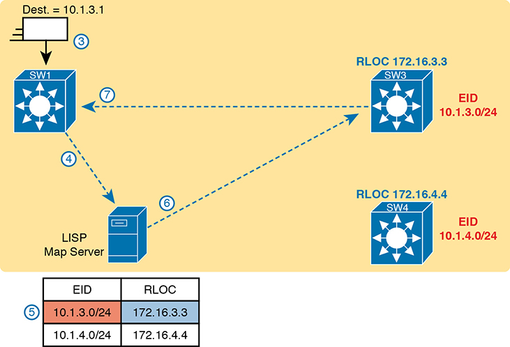
Figure 17-9 Ingress Tunnel Router SW1 Discovers Egress Tunnel Router SW3 Using LISP
To complete the story, now that ingress node SW1 knows that it can forward packets sent to endpoint 10.1.3.1 to the edge node with RLOC 172.16.3.3 (that is, SW3), SW1 encapsulates the original Ethernet frame as shown in Figure 17-9, with the original destination IP address of 10.1.3.1. It adds the IP, UDP, and VXLAN headers shown so it can deliver the message over the SDA network, with that outer IP header listing a destination IP address of the RLOC IP address, so that the message will arrive through the SDA fabric at SW3, as shown in Figure 17-10.
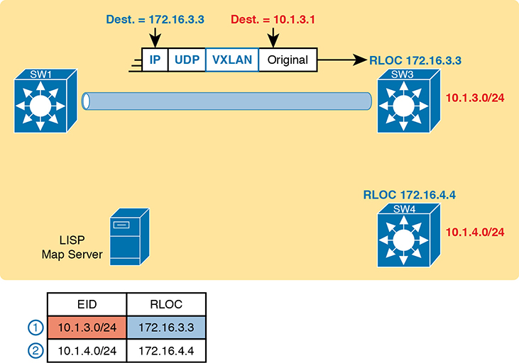
Figure 17-10 Ingress Tunnel Router (ITR) SW1 Forwards Based on LISP Mapping to SW3
At this point, you should have a basic understanding of how the SDA fabric works. The underlay includes all the switches and links, along with IP connectivity, as a basis for forwarding data across the fabric. The overlay adds a different level of logic, with endpoint traffic flowing through VXLAN tunnels. This chapter has not mentioned any reasons that SDA might want to use these tunnels, but you will see one example by the end of the chapter. Suffice it to say that with the flexible VXLAN tunnels, SDA can encode header fields that let SDA create new networking features, all without suffering a performance penalty, as all the VXLAN processing happens in an ASIC.
This chapter next focuses on DNA Center and its role in managing and controlling SDA fabrics.
DNA Center and SDA Operation
Cisco DNA Center (www.cisco.com/go/dnacenter) has two notable roles:
As the controller in a network that uses Cisco SDA
As a network management platform for traditional (non-SDA) network devices, with an expectation that one day DNA Center may become Cisco’s primary enterprise network management platform
The first role as SDA network controller gets most of the attention and is the topic of discussion in this second of the three major sections of this chapter. SDA and DNA Center go together, work closely together, and any serious use of SDA requires the use of DNA Center. At the same time, DNA Center can manage traditional network devices; the final major section of the chapter works through some comparisons.
Cisco DNA Center
Cisco DNA Center exists as a software application that Cisco delivers pre-installed on a Cisco DNA Center appliance. The software follows the same general controller architecture concepts as described in Chapter 16. Figure 17-11 shows the general ideas.
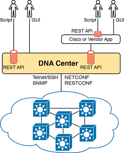
Figure 17-11 Cisco DNA Center with Northbound and Southbound Interfaces
Cisco DNA Center includes a robust northbound REST API along with a series of southbound APIs. For most of us, the northbound API matters most, because as the user of SDA networks, you interact with SDA using Cisco DNA Center’s northbound REST API or the GUI interface. (Chapter 18, “Understanding REST and JSON,” discusses the concepts behind REST APIs in more detail.)
Cisco DNA Center supports several southbound APIs so that the controller can communicate with the devices it manages. You can think of these as two categories:
Protocols to support traditional networking devices/software versions: Telnet, SSH, SNMP
Protocols to support more recent networking devices/software versions: NETCONF, RESTCONF
Cisco DNA Center needs the older protocols to be able to support the vast array of older Cisco devices and OS versions. Over time, Cisco has been adding support for NETCONF and RESTCONF to their more current hardware and software.
Cisco DNA Center and Scalable Groups
SDA creates many interesting new and powerful features beyond how traditional campus networks work. Cisco DNA Center not only enables an easier way to configure and operate those features, but it also completely changes the operational model. While the scope of CCNA does not allow us enough space to explore all of the features of SDA and DNA Center, this next topic looks at one feature as an example: scalable groups.
Issues with Traditional IP-Based Security
Imagine the life of one traditional IP ACL in an enterprise. Some requirements occurred, and an engineer built the first version of an ACL with three Access Control Entries (ACEs)—that is, access-list commands—with a permit any at the end of the list. Months later, the engineer added two more lines to the ACL, so the ACL has the number of ACEs shown in Figure 17-12. The figure notes the lines added for requests one and two with the circled numbers in the figure.
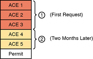
Figure 17-12 Lines (ACEs) in an ACL after Two Changes
Now think about that same ACL after four more requirements caused changes to the ACL, as noted in Figure 17-13. Some of the movement includes
The ACEs for requirement two are now at the bottom of the ACL.
Some ACEs, like ACE 5, apply to more than one of the implemented requirements.
Some requirements, like requirement number five, required ACEs that overlap with multiple other requirements.

Figure 17-13 Lines (ACEs) in an ACL after Six Changes
Now imagine your next job is to add more ACEs for the next requirement (7). However, your boss also told you to reduce the length of the ACL, removing the ACEs from that one change made last August—you remember it, right? Such tasks are problematic at best.
With the scenario in Figure 17-13, no engineer could tell from looking at the ACL whether any lines in the ACL could be safely removed. You never know if an ACE was useful for one requirement or for many. If a requirement was removed, and you were even told which old project caused the original requirement so that you could look at your notes, you would not know if removing the ACEs would harm other requirements. Most of the time, ACL management suffers with these kinds of issues:
ACEs cannot be removed from ACLs because of the risk of causing failures to the logic for some other past requirement.
New changes become more and more challenging due to the length of the ACLs.
Troubleshooting ACLs as a system—determining whether a packet would be delivered from end-to-end—becomes an even greater challenge.
SDA Security Based on User Groups
Imagine you could instead enforce security without even thinking about IP address ranges and ACLs. SDA does just that, with simple configuration, and the capability to add and remove the security policies at will.
First, for the big ideas. Imagine that over time, using SDA, six different security requirements occurred. For each project, the engineer would define the policy with DNA Center, either with the GUI or with the API. Then, as needed, DNA Center would configure the devices in the fabric to enforce the security, as shown in Figure 17-14.

Figure 17-14 DNA-C IP Security Policies (Northbound) to Simplify Operations
The SDA policy model solves the configuration and operational challenges with traditional ACLs. In fact, all those real issues with managing IP ACLs on each device are no longer issues with SDA’s group-based security model. For instance:
The engineer can consider each new security requirement separately, without analysis of an existing (possibly lengthy) ACL.
Each new requirement can be considered without searching for all the ACLs in the likely paths between endpoints and analyzing each and every ACL.
DNA Center (and related software) keeps the policies separate, with space to keep notes about the reason for the policy.
Each policy can be removed without fear of impacting the logic of the other policies.
SDA and Cisco DNA achieve this particular feature by tying security to groups of users, called scalable groups, with each group assigned a scalable group tag (SGT). Then the engineer configures a grid that identifies which SGTs can send packets to which other SGTs. For instance, the grid might include SGTs for an employee group, the Internet (for the Enterprise’s WAN routers that lead to the Internet), partner employees, and guests, with a grid like the one shown in Table 17-2.
Table 17-2 Access Table for SDA Scalable Group Access
Dest. Source |
Employee |
Internet |
Partner |
Guest |
Employee |
N/A |
Permit |
Permit |
Deny |
Internet |
Permit |
N/A |
Permit |
Permit |
Partner |
Permit |
Permit |
N/A |
Deny |
Guest |
Deny |
Permit |
Deny |
N/A |
To link this security feature back to packet forwarding, consider when a new endpoint tries to send its first packet to a new destination. The ingress SDA node starts a process by sending messages to DNA Center. DNA Center then works with security tools in the network, like Cisco’s Identity Services Engine (ISE), to identify the users and then match them to their respective SGTs. DNA Center then checks the logic similar to Table 17-2. If DNA Center sees a permit action between the source/destination pair of SGTs, DNA Center directs the edge nodes to create the VXLAN tunnel, as shown in Figure 17-15. If the security policies state that the two SGTs should not be allowed to communicate, DNA Center does not direct the fabric to create the tunnel, and the packets do not flow.
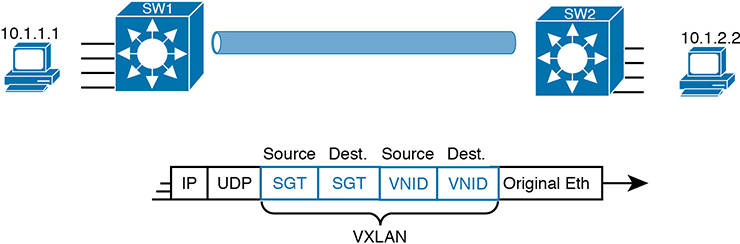
Figure 17-15 VXLAN Header with Source and Destination SGTs and VNIDs Revealed
The operational model with scalable groups greatly simplifies security configuration and ongoing maintenance of the security policy, while focusing on the real goal: controlling access based on user. From a controller perspective, the fact that Cisco DNA Center acts as much more than a management platform, and instead as a controller of the activities in the network, makes for a much more powerful set of features and capabilities.
DNA Center as a Network Management Platform
CCNA Exam topic 6.4 asks you to compare traditional network management with DNA Center:
Compare traditional campus device management with Cisco DNA Center enabled device management
Note that the exam topic does not identify which traditional management product. In fact, Cisco tends to shy away from product details in most of its career certifications. So, to think through this exam topic, you need to think in general about network management products. But it also helps to think about specific products—but temper that by focusing on the more prominent features and major functions.
This section uses Cisco Prime Infrastructure (PI) (www.cisco.com/go/primeinfrastructure) as an example of a traditional enterprise network management product. For many years, Cisco Prime Infrastructure has been Cisco’s primary network management product for the enterprise. It includes the following features:
Single-pane-of-glass: Provides one GUI from which to launch all PI functions and features
Discovery, inventory, and topology: Discovers network devices, builds an inventory, and arranges them in a topology map
Entire enterprise: Provides support for traditional enterprise LAN, WAN, and data center management functions
Methods and protocols: Uses SNMP, SSH, and Telnet, as well as CDP and LLDP, to discover and learn information about the devices in the network
Lifecycle management: Supports different tasks to install a new device (day 0), configure it to be working in production (day 1), and perform ongoing monitoring and make changes (day n)
Application visibility: Simplifies QoS configuration deployment to each device
Converged wired and wireless: Enables you to manage both the wired and wireless LAN from the same management platform
Software Image Management (SWIM): Manages software images on network devices and automates updates
Plug-and-Play: Performs initial installation tasks for new network devices after you physically install the new device, connect a network cable, and power on
PI itself runs as an application on a server platform with GUI access via a web browser. The PI server can be purchased from Cisco as a software package to be installed and run on your servers, or as a physical appliance.
The next few pages now compare and contrast DNA Center to traditional management tools like PI.
DNA Center Similarities to Traditional Management
If you read the user’s guide for DNA Center and look through all the features, you will find all the features just listed here as traditional management features. For instance, both can discover network devices and create a network topology map. Human operators (rather than automated processes) often start with the topology map, expecting notices (flashing lights, red colors) to denote issues in the network.
As an example, Figure 17-16 shows a topology map from DNA Center. Both PI and DNA Center can perform a discover process to find all the devices in the network and then build topology maps to show the devices. (Interestingly, DNA Center can work with PI, using the data discovered by PI rather than performing the discovery work again.)

Figure 17-16 DNA Center Topology Map
The GUI mechanisms are relatively intuitive, with the ability to click into additional or less detail. Figure 17-17 shows a little more detail after hovering over and clicking on one of the nodes in the topology from Figure 17-16, typical actions and results in many management products.

Figure 17-17 Hover and Click Details About One Cisco 9300 Switch from DNA Center
I encourage you to take some time to use and watch some videos about Cisco DNA Center. The “Chapter Review” section for this chapter on the companion website lists some links for good videos. Also, start at https://developer.cisco.com and look for Cisco DNA Center sandbox labs to find a place to experiment with Cisco DNA Center.
DNA Center Differences with Traditional Management
In a broad sense, there are several fundamental differences between Cisco DNA Center and traditional network management platforms like Cisco PI. The largest difference: Cisco DNA Center supports SDA, whereas other management apps do not. At the same time, given its long history, as of the time this chapter was written, Cisco PI still had some traditional management features not found in Cisco DNA Center. So think of PI as comprehensive to traditional device management, with Cisco DNA Center having many of those features, while focusing on future features like SDA support.
In terms of intent and strategy, Cisco focuses their development of Cisco DNA Center features toward simplifying the work done by enterprises, with resulting reduced costs and much faster deployment of changes. Cisco DNA Center features help make initial installation easier, simplify the work to implement features that traditionally have challenging configuration, and use tools to help you notice issues more quickly. Some of the features unique to Cisco DNA Center include
EasyQoS: Deploys QoS, one of the most complicated features to configure manually, with just a few simple choices from Cisco DNA Center
Encrypted traffic analysis: Enables Cisco DNA to use algorithms to recognize security threats even in encrypted traffic
Device 360 and Client 360: Gives a comprehensive (360-degree) view of the health of the device
Network time travel: Shows past client performance in a timeline for comparison to current behavior
Path trace: Discovers the actual path packets would take from source to destination based on current forwarding tables
Just to expound on one feature as an example, Cisco DNA Center’s Path Trace feature goes far beyond a traditional management application. A typical network management app might show a map of the network and let you click through to find the configuration on each device, including ACLs. The path trace feature goes much further. The DNA user (from the GUI or the API) specifies a source and destination host and optionally transport protocol and ports. Then the path trace feature shows a map of the path through the network and shows which ACLs are in the path, and whether they would permit or deny the packet.
All of Cisco Digital Network Architecture sets about to help customers reach some big goals: reduced costs, reduced risks, better security and compliance, faster deployment of services through automation and simplified processes, and the list goes on. Cisco DNA Center plays an important role, with all the functions available through its robust northbound API, and with its intent-based networking approach for SDA. Cisco DNA Center represents the future of network management for Cisco enterprises.
Chapter Review
One key to doing well on the exams is to perform repetitive spaced review sessions. Review this chapter’s material using either the tools in the book or interactive tools for the same material found on the book’s companion website. Refer to the “Your Study Plan” element for more details. Table 17-3 outlines the key review elements and where you can find them. To better track your study progress, record when you completed these activities in the second column.
Table 17-3 Chapter Review Tracking
Review Element |
Review Date(s) |
Resource Used |
Review key topics |
|
Book, website |
Review key terms |
|
Book, website |
Answer DIKTA questions |
|
Book, PTP |
Review All the Key Topics
Table 17-4 Key Topics for Chapter 17
Key Topic Element |
Description |
Page Number |
List |
Definitions for overlay, underlay, and fabric |
|
SDA overlay and underlay |
||
List |
SDA fabric edge, fabric border, and fabric control node roles |
|
List |
Attributes of the SDA underlay |
|
List |
SDA VXLAN tunneling benefits |
|
VXLAN encapsulation process with SDA |
||
Registering SDA endpoint IDs (EIDs) with the map server |
||
DNA Center shown controlling the fabric to implement group-based security |
||
List |
DNA Center features that go beyond traditional network management |
|
List |
Features unique to DNA Center |