Chapter 7. Configuring and Verifying Switch Interfaces
This chapter covers the following exam topics:
1.0 Network Fundamentals
1.1 Explain the role and function of network components
1.1.b L2 and L3 switches
1.4 Describe switching concepts
So far in this part, you have learned the skills to navigate the command-line interface (CLI) and use commands that configure and verify switch features. You learned about the primary purpose of a switch—forwarding Ethernet frames—and learned how to see that process in action by looking at the switch MAC address table. After learning about the switch data plane in Chapter 5, “Analyzing Ethernet LAN Switching,” you learned a few management plane features in Chapter 6, “Configuring Basic Switch Management,” like how to configure the switch to support Telnet and Secure Shell (SSH) by configuring IP address and login security.
This chapter focuses on switch interfaces in two major sections. The first section shows how you can configure and change the operation of switch interfaces: how to change the speed, duplex, or even disable the interface. The second half then focuses on how to use show commands on a switch to verify switch interface status and how to interpret the output to find some of the more common issues with switch interfaces.
“Do I Know This Already?” Quiz
Take the quiz (either here or use the PTP software) if you want to use the score to help you decide how much time to spend on this chapter. The letter answers are listed at the bottom of the page following the quiz. Appendix C, found both at the end of the book as well as on the companion website, includes both the answers and explanations. You can also find both answers and explanations in the PTP testing software.
Table 7-1 “Do I Know This Already?” Foundation Topics Section-to-Question Mapping
Foundation Topics Section |
Questions |
|---|---|
Configuring Switch Interfaces |
1–3 |
Analyzing Switch Interface Status and Statistics |
4–6 |
1. Which of the following describes a way to disable IEEE standard autonegotiation on a 10/100 port on a Cisco switch?
a. Configure the negotiate disable interface subcommand
b. Configure the no negotiate interface subcommand
c. Configure the speed 100 interface subcommand
d. Configure the duplex half interface subcommand
e. Configure the duplex full interface subcommand
f. Configure the speed 100 and duplex full interface subcommands
2. In which of the following modes of the CLI could you configure the duplex setting for interface Fast Ethernet 0/5?
a. User mode
b. Enable mode
c. Global configuration mode
d. VLAN mode
e. Interface configuration mode
3. A Cisco Catalyst switch connects with its Gigabit0/1 port to an end user’s PC. The end user, thinking the user is helping, manually sets the PC’s OS to use a speed of 1000 Mbps and to use full duplex, and disables the use of autonegotiation. The switch’s G0/1 port has default settings for speed and duplex. What speed and duplex settings will the switch decide to use? (Choose two answers.)
a. Full duplex
b. Half duplex
c. 10 Mbps
d. 1000 Mbps
4. The output of the show interfaces status command on a 2960 switch shows interface Fa0/1 in a “disabled” state. Which of the following is true about interface Fa0/1? (Choose three answers.)
a. The interface is configured with the shutdown command.
b. The show interfaces fa0/1 command will list the interface with two status codes of administratively down and line protocol down.
c. The show interfaces fa0/1 command will list the interface with two status codes of up and down.
d. The interface cannot currently be used to forward frames.
e. The interface can currently be used to forward frames.
5. Switch SW1 uses its Gigabit 0/1 interface to connect to switch SW2’s Gigabit 0/2 interface. SW2’s Gi0/2 interface is configured with the speed 1000 and duplex full commands. SW1 uses all defaults for interface configuration commands on its Gi0/1 interface. Which of the following are true about the link after it comes up? (Choose two answers.)
a. The link works at 1000 Mbps (1 Gbps).
b. SW1 attempts to run at 10 Mbps because SW2 has effectively disabled IEEE standard autonegotiation.
c. The link runs at 1 Gbps, but SW1 uses half duplex and SW2 uses full duplex.
d. Both switches use full duplex.
6. Switch SW1 connects via a cable to switch SW2’s G0/1 port. Which of the following conditions is the most likely to cause SW1’s late collision counter to continue to increment?
a. SW2’s G0/1 has been configured with a shutdown interface subcommand.
b. The two switches have been configured with different values on the speed interface subcommand.
c. A duplex mismatch exists with SW1 set to full duplex.
d. A duplex mismatch exists with SW1 set to half duplex.
Answers to the “Do I Know This Already?” quiz:
1 F
2 E
3 A, D
4 A, B, D
5 A, D
6 D
Foundation Topics
Configuring Switch Interfaces
IOS uses the term interface to refer to physical ports used to forward data to and from other devices. Each interface can be configured with several settings, each of which might differ from interface to interface. IOS uses interface subcommands to configure these settings. Each of these settings may be different from one interface to the next, so you would first identify the specific interface, and then configure the specific setting.
This section begins with a discussion of three relatively basic per-interface settings: the port speed, duplex, and a text description. Following that, the text takes a short look at a pair of the most common interface subcommands: the shutdown and no shutdown commands, which administratively disable and enable the interface, respectively. This section ends with a discussion about autonegotiation concepts, which in turn dictates what settings a switch chooses to use when using autonegotiation.
Configuring Speed, Duplex, and Description
Switch interfaces that support multiple speeds (10/100 and 10/100/1000 interfaces), by default, will autonegotiate what speed to use. However, you can configure the speed and duplex settings with the duplex {auto | full | half} and speed {auto | 10 | 100 | 1000} interface subcommands. Simple enough.
Most of the time, using autonegotiation makes good sense, so when you set the duplex and speed manually using these commands, you typically have a good reason to do so. For instance, maybe you want to set the speed to the fastest possible on links between switches just to avoid the chance that autonegotiation chooses a slower speed.
The description text interface subcommand lets you add a text description to the interface. For instance, if you have good reason to configure the speed and duplex on a port, maybe add a description that says why you did. Example 7-1 shows how to configure duplex and speed, as well as the description command, which is simply a text description that can be configured by the administrator.
Example 7-1 Configuring speed, duplex, and description on Switch Emma
Emma# configure terminal
Enter configuration commands, one per line. End with CNTL/Z.
Emma(config)# interface FastEthernet 0/1
Emma(config-if)# duplex full
Emma(config-if)# speed 100
Emma(config-if)# description Printer on 3rd floor, Preset to 100/full
Emma(config-if)# exit
Emma(config)# interface range FastEthernet 0/11 - 20
Emma(config-if-range)# description end-users connect here
Emma(config-if-range)# ^Z
Emma#
First, focus on the mechanics of moving around in configuration mode again by looking closely at the command prompts. The various interface commands move the user from global mode into interface configuration mode for a specific interface. For instance, the example configures the duplex, speed, and description commands all just after the interface FastEthernet 0/1 command, which means that all three of those configuration settings apply to interface Fa0/1, and not to the other interfaces.
The show interfaces status command lists much of the detail configured in Example 7-1, even with only one line of output per interface. Example 7-2 shows an example, just after the configuration in Example 7-1 was added to the switch.
Example 7-2 Displaying Interface Status
Emma# show interfaces status
Port      Name                 Status       Vlan      Duplex  Speed Type
Fa0/1     Printer on 3rd floo  notconnect   1           full    100 10/100BaseTX
Fa0/2                          notconnect   1           auto   auto 10/100BaseTX
Fa0/3                          notconnect   1           auto   auto 10/100BaseTX
Fa0/4                          connected    1         a-full  a-100 10/100BaseTX
Fa0/5                          notconnect   1           auto   auto 10/100BaseTX
Fa0/6                          connected    1         a-full  a-100 10/100BaseTX
Fa0/7                          notconnect   1           auto   auto 10/100BaseTX
Fa0/8                          notconnect   1           auto   auto 10/100BaseTX
Fa0/9                          notconnect   1           auto   auto 10/100BaseTX
Fa0/10                         notconnect   1           auto   auto 10/100BaseTX
Fa0/11     end-users connect   notconnect   1           auto   auto 10/100BaseTX
Fa0/12     end-users connect   notconnect   1           auto   auto 10/100BaseTX
Fa0/13     end-users connect   notconnect   1           auto   auto 10/100BaseTX
Fa0/14     end-users connect   notconnect   1           auto   auto 10/100BaseTX
Fa0/15     end-users connect   notconnect   1           auto   auto 10/100BaseTX
Fa0/16     end-users connect   notconnect   1           auto   auto 10/100BaseTX
Fa0/17     end-users connect   notconnect   1           auto   auto 10/100BaseTX
Fa0/18     end-users connect   notconnect   1           auto   auto 10/100BaseTX
Fa0/19     end-users connect   notconnect   1           auto   auto 10/100BaseTX
Fa0/20     end-users connect   notconnect   1           auto   auto 10/100BaseTX
Fa0/21                         notconnect   1           auto   auto 10/100BaseTX
Fa0/22                         notconnect   1           auto   auto 10/100BaseTX
Fa0/23                         notconnect   1           auto   auto 10/100BaseTX
Fa0/24                         notconnect   1           auto   auto 10/100BaseTX
Gi0/1                          notconnect   1           auto   auto 10/100/1000BaseTX
Gi0/2                          notconnect   1           auto   auto 10/100/1000BaseTX
Working through the output in the example:
FastEthernet 0/1 (Fa0/1): This output lists the first few characters of the configured description. It also lists the configured speed of 100 and duplex full per the speed and duplex commands in Example 7-1. However, it also states that Fa0/1 has a status of notconnect, meaning that the interface is not currently working. (That switch port did not have a cable connected when collecting this example, on purpose.)
FastEthernet 0/2 (Fa0/2): Example 7-1 did not configure this port at all. This port had all default configuration. Note that the “auto” text under the speed and duplex heading means that this port will attempt to autonegotiate both settings when the port comes up. However, this port also does not have a cable connected (again on purpose, for comparison).
FastEthernet 0/4 (Fa0/4): Like Fa0/2, this port has all default configuration but was cabled to another working device to give yet another contrasting example. This device completed the autonegotiation process, so instead of “auto” under the speed and duplex headings, the output lists the negotiated speed and duplex (a-full and a-100). Note that the text includes the a- to mean that the listed speed and duplex values were autonegotiated.
Configuring Multiple Interfaces with the interface range Command
The bottom of the configuration in Example 7-1 shows a way to shorten your configuration work when making the same setting on multiple consecutive interfaces. To do so, use the interface range command. In the example, the interface range FastEthernet 0/11 - 20 command tells IOS that the next subcommand(s) apply to interfaces Fa0/11 through Fa0/20. You can define a range as long as all interfaces are the same type and are numbered consecutively.
Note
This book spells out all parameters fully to avoid confusion. However, most everyone abbreviates what they type in the CLI to the shortest unique abbreviation. For instance, the configuration commands int f0/1 and int ran f0/11 - 20 would also be acceptable.
IOS does not actually put the interface range command into the configuration. Instead, it acts as if you had typed the subcommand under every single interface in the specified range. Example 7-3 shows an excerpt from the show running-config command, listing the configuration of interfaces F0/11–12 from the configuration in Example 7-1. The example shows the same description command on both interfaces; to save space, the example does not bother to show all 10 interfaces that have the same description text.
Example 7-3 How IOS Expands the Subcommands Typed After interface range
Emma# show running-config
! Lines omitted for brevity
interface FastEthernet0/11
 description end-users connect here
!
interface FastEthernet0/12
 description end-users connect here
! Lines omitted for brevity
Administratively Controlling Interface State with shutdown
As you might imagine, network engineers need a way to bring down an interface without having to travel to the switch and remove a cable. In short, we need to be able to decide which ports should be enabled and which should be disabled.
In an odd turn of phrase, Cisco uses two interface subcommands to configure the idea of administratively enabling and disabling an interface: the shutdown command (to disable) and the no shutdown command (to enable). While the no shutdown command might seem like an odd command to enable an interface at first, you will use this command a lot in the lab, and it will become second nature. (Most people, in fact, use the abbreviations shut and no shut.)
Example 7-4 shows an example of disabling an interface using the shutdown interface subcommand. In this case, switch SW1 has a working interface F0/1. The user connects at the console and disables the interface. IOS generates a log message each time an interface fails or recovers, and log messages appear at the console, as shown in the example.

Example 7-4 Administratively Disabling an Interface with shutdown
SW1# configure terminal
Enter configuration commands, one per line. End with CNTL/Z.
SW1(config)# interface fastEthernet 0/1
SW1(config-if)# shutdown
SW1(config-if)#
*Mar 2 03:02:19.701: %LINK-5-CHANGED: Interface FastEthernet0/1, changed state to
administratively down
*Mar 2 03:02:20.708: %LINEPROTO-5-UPDOWN: Line protocol on Interface FastEthernet0/1,
changed state to down
To bring the interface back up again, all you have to do is follow the same process but use the no shutdown command instead.
Before leaving the simple but oddly named shutdown/no shutdown commands, take a look at two important show commands that list the status of a shutdown interface. The show interfaces status command lists one line of output per interface, and when shut down, lists the interface status as “disabled.” That makes logical sense to most people. The show interfaces command (without the status keyword) lists many lines of output per interface, giving a much more detailed picture of interface status and statistics. With that command, the interface status comes in two parts, with one part using the phrase “administratively down,” matching the highlighted log message in Example 7-4.
Example 7-5 shows an example of each of these commands. Note that both examples also use the F0/1 parameter (short for Fast Ethernet0/1), which limits the output to the messages about F0/1 only. Also note that F0/1 is still shut down at this point.
Example 7-5 The Different Status Information About Shutdown in Two Different show Commands
SW1# show interfaces f0/1 status

Port      Name               Status       Vlan       Duplex  Speed Type
Fa0/1                        disabled     1            auto   auto 10/100BaseTX

SW1# show interfaces f0/1
FastEthernet0/1 is administratively down, line protocol is down (disabled)
  Hardware is Fast Ethernet, address is 1833.9d7b.0e81 (bia 1833.9d7b.0e81)
  MTU 1500 bytes, BW 10000 Kbit/sec, DLY 1000 usec,
     reliability 255/255, txload 1/255, rxload 1/255
  Encapsulation ARPA, loopback not set
  Keepalive set (10 sec)
  Auto-duplex, Auto-speed, media type is 10/100BaseTX
  input flow-control is off, output flow-control is unsupported
  ARP type: ARPA, ARP Timeout 04:00:00
  Last input never, output 00:00:36, output hang never
  Last clearing of "show interface" counters never
  Input queue: 0/75/0/0 (size/max/drops/flushes); Total output drops: 0
  Queueing strategy: fifo
  Output queue: 0/40 (size/max)
  5 minute input rate 0 bits/sec, 0 packets/sec
  5 minute output rate 0 bits/sec, 0 packets/sec
     164 packets input, 13267 bytes, 0 no buffer
     Received 164 broadcasts (163 multicasts)
     0 runts, 0 giants, 0 throttles
     0 input errors, 0 CRC, 0 frame, 0 overrun, 0 ignored
     0 watchdog, 163 multicast, 0 pause input
     0 input packets with dribble condition detected
     66700 packets output, 5012302 bytes, 0 underruns
     0 output errors, 0 collisions, 1 interface resets
     0 unknown protocol drops
     0 babbles, 0 late collision, 0 deferred
     0 lost carrier, 0 no carrier, 0 pause output
     0 output buffer failures, 0 output buffers swapped out
Removing Configuration with the no Command
One purpose for the specific commands shown in Part II of the book is to teach you about that command. In some cases, the commands are not the end goal, and the text is attempting to teach you something about how the CLI works. This next short topic is more about the process than about the commands.
With some IOS configuration commands (but not all), you can revert to the default setting by issuing a no version of the command. What does that mean? Let me give you a few examples:
If you earlier had configured speed 100 on an interface, the no speed command on that same interface reverts to the default speed setting (which happens to be speed auto).
Same idea with the duplex command: an earlier configuration of duplex half or duplex full, followed by no duplex on the same interface, reverts the configuration back to the default of duplex auto.
If you had configured a description command with some text, to go back to the default state of having no description command at all for that interface, use the no description command.
Example 7-6 shows the process. In this case, switch SW1’s F0/2 port has been configured with speed 100, duplex half, description link to 2901-2, and shutdown. You can see evidence of all four settings in the command that begins the example. (This command lists the running-config, but only the part for that one interface.) The example then shows the no versions of those commands and closes with a confirmation that all the commands have reverted to default.
Example 7-6 Removing Various Configuration Settings Using the no Command
SW1# show running-config interface f0/2
Building configuration...

Current configuration : 95 bytes
!
interface FastEthernet0/2
 description link to 2901-2
 shutdown
 speed 100
 duplex half
end

SW1# configure terminal
Enter configuration commands, one per line. End with CNTL/Z.
SW1(config)# interface fastethernet 0/2
SW1(config-if)# no speed
SW1(config-if)# no duplex
SW1(config-if)# no description
SW1(config-if)# no shutdown
SW1(config-if)# ^Z
SW1#
SW1# show running-config interface f0/2
Building configuration...
Current configuration : 33 bytes
!
interface FastEthernet0/2
end
SW1#
Note
The show running-config and show startup-config commands typically do not display default configuration settings, so the absence of commands listed under interface F0/2 at the end of the example means that those commands now use default values.
Autonegotiation
For any 10/100 or 10/100/1000 interfaces—that is, interfaces that can run at different speeds—Cisco Catalyst switches default to a setting of duplex auto and speed auto. As a result, those interfaces attempt to automatically determine the speed and duplex setting to use. Alternatively, you can configure most devices, switch interfaces included, to use a specific speed and/or duplex.
In practice, using autonegotiation is easy: just leave the speed and duplex at the default setting, and let the switch port negotiate what settings to use on each port. However, problems can occur due to unfortunate combinations of configuration. Therefore, this next topic walks through more detail about the concepts behind autonegotiation, so you know better how to interpret the meaning of the switch show commands and when to choose to use a particular configuration setting.
Autonegotiation Under Working Conditions
Ethernet devices on the ends of a link must use the same standard; otherwise, they cannot correctly send data. For example, a NIC cannot use 100BASE-T, which uses a two-pair UTP cable with a 100-Mbps speed, while the switch port on the other end of the link uses 1000BASE-T. Even if you used a cable that works with Gigabit Ethernet, the link would not work with one end trying to send at 100 Mbps while the other tried to receive the data at 1000 Mbps.
Upgrading to new and faster Ethernet standards becomes a problem because both ends have to use the same standard. For example, if you replace an old PC with a new one, the old one might have been using 100BASE-T while the new one uses 1000BASE-T. The switch port on the other end of the link needs to now use 1000BASE-T, so you upgrade the switch. If that switch had ports that would use only 1000BASE-T, you would need to upgrade all the other PCs connected to the switch. So, having both PC network interface cards (NIC) and switch ports that support multiple standards/speeds makes it much easier to migrate to the next better standard.
The IEEE autonegotiation protocol helps makes it much easier to operate a LAN when NICs and switch ports support multiple speeds. IEEE autonegotiation (IEEE standard 802.3u) defines a protocol that lets the two UTP-based Ethernet nodes on a link negotiate so that they each choose to use the same speed and duplex settings. The protocol messages flow outside the normal Ethernet electrical frequencies as out-of-band signals over the UTP cable. Basically, each node states what it can do, and then each node picks the best options that both nodes support: the fastest speed and the best duplex setting, with full duplex being better than half duplex.
Note
Autonegotiation relies on the fact that the IEEE uses the same wiring pinouts for 10BASE-T and 100BASE-T, and that 1000BASE-T simply adds to those pinouts, adding two pairs.
Many networks use autonegotiation every day, particularly between user devices and the access layer LAN switches, as shown in Figure 7-1. The company installed four-pair cabling of the right quality to support 1000BASE-T, to be ready to support Gigabit Ethernet. As a result, the wiring supports 10-Mbps, 100-Mbps, and 1000-Mbps Ethernet options. Both nodes on each link send autonegotiation messages to each other. The switch in this case has all 10/100/1000 ports, while the PC NICs support different options.

Figure 7-1 IEEE Autonegotiation Results with Both Nodes Working Correctly
The following list breaks down the logic, one PC at a time:
PC1: The switch port claims it can go as fast as 1000 Mbps, but PC1’s NIC claims a top speed of 10 Mbps. Both the PC and the switch choose the fastest speed that each supports (10 Mbps) and the best duplex that each supports (full).
PC2: PC2 claims a best speed of 100 Mbps, which means it can use 10BASE-T or 100BASE-T. The switch port and NIC negotiate to use the best speed of 100 Mbps and full duplex.
PC3: It uses a 10/100/1000 NIC, supporting all three speeds and standards, so both the NIC and switch port choose 1000 Mbps and full duplex.
Autonegotiation Results When Only One Node Uses Autonegotiation
Figure 7-1 shows the IEEE autonegotiation results when both nodes use the process. However, most Ethernet devices can disable autonegotiation, so it is just as important to know what happens when a node tries to use autonegotiation but the node gets no response.
Disabling autonegotiation is not always a bad idea. For instance, many network engineers disable autonegotiation on links between switches and simply configure the desired speed and duplex on both switches. However, mistakes can happen when one device on an Ethernet predefines speed and duplex (and disables autonegotiation), while the device on the other end attempts autonegotiation. In that case, the link might not work at all, or it might just work poorly.
Note
Configuring both the speed and duplex on a Cisco Catalyst switch interface disables autonegotiation.
IEEE autonegotiation defines some rules (defaults) that nodes should use as defaults when autonegotiation fails—that is, when a node tries to use autonegotiation but hears nothing from the device. The rules:
Speed: Use your slowest supported speed (often 10 Mbps).
Duplex: If your speed = 10 or 100, use half duplex; otherwise, use full duplex.
Cisco switches can make a better choice than that base IEEE speed default because Cisco switches can actually sense the speed used by other nodes, even without IEEE autonegotiation. As a result, Cisco switches use this slightly different logic to choose the speed when autonegotiation fails:
Speed: Sense the speed (without using autonegotiation), but if that fails, use the IEEE default (slowest supported speed, often 10 Mbps).
Duplex: Use the IEEE defaults: If speed = 10 or 100, use half duplex; otherwise, use full duplex.
Note
Ethernet interfaces using speeds faster than 1 Gbps always use full duplex.
Figure 7-2 shows three examples in which three users change their NIC settings and disable autonegotiation, while the switch (with all 10/100/1000 ports) attempts autonegotiation. That is, the switch ports all default to speed auto and duplex auto. The top of the figure shows the configured settings on each PC NIC, with the choices made by the switch listed next to each switch port.
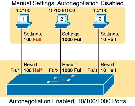
Figure 7-2 IEEE Autonegotiation Results with Autonegotiation Disabled on One Side
Reviewing each link, left to right:
PC1: The switch receives no autonegotiation messages, so it senses the electrical signal to learn that PC1 is sending data at 100 Mbps. The switch uses the IEEE default duplex based on the 100 Mbps speed (half duplex).
PC2: The switch uses the same steps and logic as with the link to PC1, except that the switch chooses to use full duplex because the speed is 1000 Mbps.
PC3: The user picks poorly, choosing the slower speed (10 Mbps) and the worse duplex setting (half). However, the Cisco switch senses the speed without using IEEE autonegotiation and then uses the IEEE duplex default for 10-Mbps links (half duplex).
PC1 shows a classic and unfortunately common end result: a duplex mismatch. The two nodes (PC1 and SW1’s port G0/1) both use 100 Mbps, so they can send data. However, PC1, using full duplex, does not attempt to use carrier sense multiple access with collision detection (CSMA/CD) logic and sends frames at any time. Switch port F0/1, with half duplex, does use CSMA/CD. As a result, switch port F0/1 will believe collisions occur on the link, even if none physically occur. The switch port will stop transmitting, back off, resend frames, and so on. As a result, the link is up, but it performs poorly. The upcoming section titled “Interface Speed and Duplex Issues” will revisit this problem with a focus on how to recognize the symptoms of a duplex mismatch.
Autonegotiation and LAN Hubs
LAN hubs also impact how autonegotiation works. Basically, hubs do not react to autonegotiation messages, and they do not forward the messages. As a result, devices connected to a hub must use the IEEE rules for choosing default settings, which often results in the devices using 10 Mbps and half duplex.
Figure 7-3 shows an example of a small Ethernet LAN that uses a 20-year-old 10BASE-T hub. In this LAN, all devices and switch ports are 10/100/1000 ports. The hub supports only 10BASE-T.

Figure 7-3 IEEE Autonegotiation with a LAN Hub
Note that the devices on the right need to use half duplex because the hub requires the use of the CSMA/CD algorithm to avoid collisions.
Note
If you would like to learn more about collision domains and the impact of these older LAN hubs, look to the companion website for Appendix K, “Analyzing Ethernet LAN Designs,” to the section titled “Ethernet Collision Domains.”
Analyzing Switch Interface Status and Statistics
Now that you have seen some of the ways to configure switch interfaces, the rest of the chapter takes a closer look at how to verify the interfaces work correctly. This section also looks at those more unusual cases in which the interface is working but not working well, as revealed by different interface status codes and statistics.
Interface Status Codes and Reasons for Nonworking States
Cisco switches actually use two different sets of interface status codes—one set of two codes (words) that use the same conventions as do router interface status codes, and another set with a single code (word). Both sets of status codes can determine whether an interface is working.
The switch show interfaces and show interfaces description commands list the two-code status named the line status and protocol status. The line status generally refers to whether Layer 1 is working, with protocol status generally referring to whether Layer 2 is working.
Note
This book refers to these two status codes in shorthand by just listing the two codes with a slash between them, such as up/up.
The single-code interface status corresponds to different combinations of the traditional two-code interface status codes and can be easily correlated to those codes. For example, the show interfaces status command lists a single-word state of connected state for working interfaces, with the same meaning as the two-word up/up state seen with the show interfaces and show interfaces description commands. Table 7-2 lists the code combinations and some root causes that could have caused a particular interface status.
Table 7-2 LAN Switch Interface Status Codes
Line Status |
Protocol Status |
Interface Status |
Typical Root Cause |
|---|---|---|---|
administratively down |
down |
disabled |
The shutdown command is configured on the interface. |
down |
down |
notconnect |
No cable; bad cable; wrong cable pinouts; speed mismatch; neighboring device is (a) powered off, (b) shutdown, or (c) error disabled. |
up |
down |
notconnect |
Not expected on LAN switch physical interfaces. |
down |
down (err-disabled) |
err-disabled |
Port security has disabled the interface. |
up |
up |
connected |
The interface is working. |
Examining the notconnect state for a moment, note that this state has many causes that have been mentioned through this book. For example, using incorrect cabling pinouts, instead of the correct pinouts explained in Chapter 2, “Fundamentals of Ethernet LANs,” causes a problem. However, one topic can be particularly difficult to troubleshoot—the possibility for both speed and duplex mismatches, as explained in the next section.
As you can see in the table, having a bad cable is just one of many reasons for the down/down state (or notconnect, per the show interfaces status command). Some examples of the root causes of cabling problems include the following:
The installation of any equipment that uses electricity, even non-IT equipment, can interfere with the transmission on the cabling and make the link fail.
The cable could be damaged, for example, if it lies under carpet. If the user’s chair keeps squashing the cable, eventually the electrical signal can degrade.
Although optical cables do not suffer from electromagnetic interference (EMI), someone can try to be helpful and move a fiber-optic cable out of the way—bending it too much. A bend into too tight a shape can prevent the cable from transmitting bits (called macrobending).
For the other interface states listed in Table 7-2, only the up/up (connected) state needs more discussion. An interface can be in a working state, and it might really be working—or it might be working in a degraded state. The next few topics discuss how to examine an up/up (connected) interface to find out whether it is working well or having problems.
Interface Speed and Duplex Issues
To discuss some of the speed and duplex issues, first consider the output from the show interfaces status and show interfaces commands as demonstrated in Example 7-7. The first of these commands lists a one-line summary of the interface status, while the second command gives many details—but surprisingly, the briefer show interfaces status command tells us more about autonegotiation.
Example 7-7 Displaying Speed and Duplex Settings on Switch Interfaces
SW1# show interfaces status

Port      Name               Status       Vlan       Duplex  Speed Type
Fa0/1                        notconnect   1            auto   auto 10/100BaseTX
Fa0/2                        notconnect   1            auto   auto 10/100BaseTX
Fa0/3                        notconnect   1            auto   auto 10/100BaseTX
Fa0/4                        connected    1          a-full  a-100 10/100BaseTX
Fa0/5                        connected    1          a-full  a-100 10/100BaseTX
Fa0/6                        notconnect   1            auto   auto 10/100BaseTX
Fa0/7                        notconnect   1            auto   auto 10/100BaseTX
Fa0/8                        notconnect   1            auto   auto 10/100BaseTX
Fa0/9                        notconnect   1            auto   auto 10/100BaseTX
Fa0/10                       notconnect   1            auto   auto 10/100BaseTX
Fa0/11                       connected    1          a-full     10 10/100BaseTX
Fa0/12                       connected    1            half    100 10/100BaseTX
Fa0/13                       connected    1          a-full  a-100 10/100BaseTX
Fa0/14                       disabled     1            auto   auto 10/100BaseTX
! Lines omitted for brevity

SW1# show interfaces fa0/13
FastEthernet0/13 is up, line protocol is up (connected)
   Hardware is Fast Ethernet, address is 0019.e86a.6f8d (bia 0019.e86a.6f8d)
   MTU 1500 bytes, BW 100000 Kbit, DLY 100 usec,
      reliability 255/255, txload 1/255, rxload 1/255
   Encapsulation ARPA, loopback not set
   Keepalive set (10 sec)
   Full-duplex, 100Mbps, media type is 10/100BaseTX
   input flow-control is off, output flow-control is unsupported
   ARP type: ARPA, ARP Timeout 04:00:00
   Last input 00:00:05, output 00:00:00, output hang never
   Last clearing of "show interface" counters never
   Input queue: 0/75/0/0 (size/max/drops/flushes); Total output drops: 0
   Queueing strategy: fifo
   Output queue: 0/40 (size/max)
   5 minute input rate 0 bits/sec, 0 packets/sec
   5 minute output rate 0 bits/sec, 0 packets/sec
      85022 packets input, 10008976 bytes, 0 no buffer
      Received 284 broadcasts (0 multicast)
      0 runts, 0 giants, 0 throttles
      0 input errors, 0 CRC, 0 frame, 0 overrun, 0 ignored
      0 watchdog, 281 multicast, 0 pause input
      0 input packets with dribble condition detected
      95226 packets output, 10849674 bytes, 0 underruns
      0 output errors, 0 collisions, 1 interface resets
      0 unknown protocol drops
      0 babbles, 0 late collision, 0 deferred
      0 lost carrier, 0 no carrier, 0 PAUSE output
      0 output buffer failures, 0 output buffers swapped out
Although both commands in the example can be useful, only the show interfaces status command implies how the switch determined the speed and duplex settings. The command output lists autonegotiated settings with a prefix of a- and the manually set values without the a- prefix.
For example, consider ports Fa0/12 and Fa0/13 in the output of the show interfaces status command. For Fa0/13, a-full means full duplex as autonegotiated, whereas half on Fa0/12 means half duplex but as manually configured. The example shades the command output that implies that the switch’s Fa0/12 interface’s speed and duplex were not found through autonegotiation, but Fa0/13 did use autonegotiation.
In comparison, note that the show interfaces fa0/13 command (without the status option) simply lists the speed and duplex for interface Fast Ethernet 0/13, with nothing implying that the values were learned through autonegotiation.
When the IEEE autonegotiation process works on both devices—that is, both are sending autonegotiation messages—both devices agree to the fastest speed and best duplex supported by both devices. However, when one device uses autonegotiation and the other disables it, the first device must resort to default settings as detailed earlier in section “Autonegotiation Results When Only One Node Uses Autonegotiation.” As a reminder, those defaults are
Speed: Sense the speed (without using autonegotiation), but if that fails, use the IEEE default (slowest supported speed, often 10 Mbps).
Duplex: Use the IEEE defaults: If speed = 10 or 100, use half duplex; otherwise, use full duplex.
When a switch must use its defaults, it should get the speed correct, but it may choose the wrong duplex setting, creating a duplex mismatch.
For example, in Figure 7-4, imagine that SW2’s Gi0/2 interface was configured with the speed 100 and duplex full commands (these settings are not recommended on a Gigabit-capable interface, by the way). On Cisco switches, configuring both the speed and duplex commands disables IEEE autonegotiation on that port. If SW1’s Gi0/1 interface tries to use autonegotiation, SW1 would also use a speed of 100 Mbps, but default to use half duplex. Example 7-8 shows the results of this specific case on SW1.
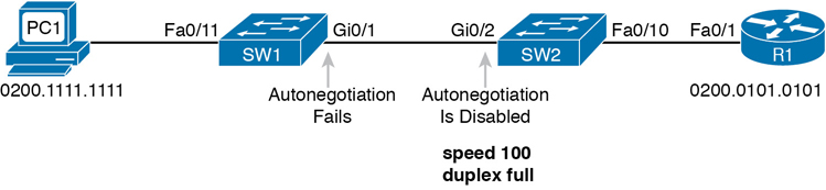
Figure 7-4 Conditions to Create a Duplex Mismatch Between SW1 and SW2
Example 7-8 Confirming Duplex Mismatch on Switch SW1
SW1# show interfaces gi0/1 status

Port      Name               Status       Vlan       Duplex  Speed Type
Gi0/1                        connected    trunk      a-half  a-100 10/100/1000BaseTX
First, note that even though SW1 had to use an autonegotiation default, the show interfaces status command still shows the speed and duplex with the a- prefix. SW2’s port was manually set to 100/Full, so SW1 sensed the speed and runs at 100 Mbps; however, the autonegotiation rules then tell SW1 to use half duplex, as confirmed by the output in Example 7-8.
The output does not identify the duplex mismatch in any way; in fact, finding a duplex mismatch can be much more difficult than finding a speed mismatch. For instance, if you purposefully set the speed on the link in Figure 7-4 to be 10 Mbps on one switch and 100 Mbps on the other, both switches would list the port in a down/down or notconnect state. However, in the case shown in Example 7-8, with a duplex mismatch, if the duplex settings do not match on the ends of an Ethernet segment, the switch interface will still be in a connected (up/up) or connected state.
Not only does the show command give an appearance that the link has no issues, but the link will likely work poorly, with symptoms of intermittent problems. The reason is that the device using half duplex (SW1 in this case) uses carrier sense multiple access collision detect (CSMA/CD) logic, waiting to send when receiving a frame, believing collisions occur when they physically do not—and actually stopping sending a frame because the switch thinks a collision occurred. With enough traffic load, the interface could be in a connect state, but it’s extremely inefficient for passing traffic.
To identify duplex mismatch problems, check the duplex setting on each end of the link to see if the values mismatch. You can also watch for incrementing collision and late collision counters, as explained in the next section.
Common Layer 1 Problems on Working Interfaces
When the interface reaches the connect (up/up) state, the switch considers the interface to be working. The switch, of course, tries to use the interface, and at the same time, the switch keeps various interface counters. These interface counters can help identify problems that can occur even though the interface is in a connect state, like issues related to the duplex mismatch problem that was just described. This section explains some of the related concepts and a few of the most common problems.
Whenever the physical transmission has problems, the receiving device might receive a frame whose bits have changed values. These frames do not pass the error detection logic as implemented in the FCS field in the Ethernet trailer, as covered in Chapter 2. The receiving device discards the frame and counts it as some kind of input error. Cisco switches list this error as a CRC error, as highlighted in Example 7-9. (Cyclic redundancy check [CRC] is a term related to how the frame check sequence [FCS] math detects an error.)
Example 7-9 Interface Counters for Layer 1 Problems
SW1# show interfaces fa0/13
! lines omitted for brevity
     Received 284 broadcasts (0 multicast)
     0 runts, 0 giants, 0 throttles
     0 input errors, 0 CRC, 0 frame, 0 overrun, 0 ignored
     0 watchdog, 281 multicast, 0 pause input
     0 input packets with dribble condition detected
     95226 packets output, 10849674 bytes, 0 underruns
     0 output errors, 0 collisions, 1 interface resets
     0 unknown protocol drops
     0 babbles, 0 late collision, 0 deferred
     0 lost carrier, 0 no carrier, 0 PAUSE output
     0 output buffer failures, 0 output buffers swapped out
The number of input errors and the number of CRC errors are just a few of the counters in the output of the show interfaces command. The challenge is to decide which counters you need to think about, which ones show that a problem is happening, and which ones are normal and of no concern.
The example highlights several of the counters as examples so that you can start to understand which ones point to problems and which ones are just counting normal events that are not problems. The following list shows a short description of each highlighted counter, in the order shown in the example:
Runts: Frames that did not meet the minimum frame size requirement (64 bytes, including the 18-byte destination MAC, source MAC, type, and FCS). Can be caused by collisions.
Giants: Frames that exceed the maximum frame size requirement (1518 bytes, including the 18-byte destination MAC, source MAC, type, and FCS).
Input Errors: A total of many counters, including runts, giants, no buffer, CRC, frame, overrun, and ignored counts.
CRC: Received frames that did not pass the FCS math; can be caused by collisions.
Frame: Received frames that have an illegal format, for example, ending with a partial byte; can be caused by collisions.
Packets Output: Total number of packets (frames) forwarded out the interface.
Output Errors: Total number of packets (frames) that the switch port tried to transmit, but for which some problem occurred.
Collisions: Counter of all collisions that occur when the interface is transmitting a frame.
Late Collisions: The subset of all collisions that happen after the 64th byte of the frame has been transmitted. (In a properly working Ethernet LAN, collisions should occur within the first 64 bytes; late collisions today often point to a duplex mismatch.)
Note that many of these counters occur as part of the CSMA/CD process used when half duplex is enabled. Collisions occur as a normal part of the half-duplex logic imposed by CSMA/CD, so a switch interface with an increasing collisions counter might not even have a problem. However, one problem, called late collisions, points to the classic duplex mismatch problem.
If a LAN design follows cabling guidelines, all collisions should occur by the end of the 64th byte of any frame. When a switch has already sent 64 bytes of a frame, and the switch receives a frame on that same interface, the switch senses a collision. In this case, the collision is a late collision, and the switch increments the late collision counter in addition to the usual CSMA/CD actions to send a jam signal, wait a random time, and try again.
With a duplex mismatch, like the mismatch between SW1 and SW2 in Figure 7-4, the half-duplex interface will likely see the late collisions counter increment. Why? The half-duplex interface sends a frame (SW1), but the full-duplex neighbor (SW2) sends at any time, even after the 64th byte of the frame sent by the half-duplex switch. So, just keep repeating the show interfaces command, and if you see the late collisions counter incrementing on a half-duplex interface, you might have a duplex mismatch problem.
A working interface (in an up/up state) can still suffer from issues related to the physical cabling as well. The cabling problems might not be bad enough to cause a complete failure, but the transmission failures result in some frames failing to pass successfully over the cable. For example, excessive interference on the cable can cause the various input error counters to keep growing larger, especially the CRC counter. In particular, if the CRC errors grow, but the collisions counters do not, the problem might simply be interference on the cable. (The switch counts each collided frame as one form of input error as well.)
Chapter Review
One key to doing well on the exams is to perform repetitive spaced review sessions. Review this chapter’s material using either the tools in the book or interactive tools for the same material found on the book’s companion website. Refer to the “Your Study Plan” element section titled “Step 2: Build Your Study Habits Around the Chapter” for more details. Table 7-3 outlines the key review elements and where you can find them. To better track your study progress, record when you completed these activities in the second column.
Table 7-3 Chapter Review Tracking
Review Element |
Review Date(s) |
Resource Used |
|---|---|---|
Review key topics |
|
Book, website |
Review key terms |
|
Book, website |
Answer DIKTA questions |
|
Book, PTP |
Review command tables |
|
Book |
Review memory tables |
|
Website |
Do labs |
|
Sim Lite, blog |
Review All the Key Topics
Table 7-4 Key Topics for Chapter 7
Key Topic Element |
Description |
Page Number |
|---|---|---|
Example of configuring speed, duplex, and description |
153 |
|
Example of disabling an interface using the shutdown command |
155 |
|
List |
Key decision rules for autonegotiation on Cisco switches when the other device does not participate |
160 |
Two types of interface state terms and their meanings |
163 |
|
Example that shows how to find the speed and duplex settings, as well as whether they were learned through autonegotiation |
164 |
|
List |
Defaults for IEEE autonegotiation |
165 |
List |
Explanations of different error statistics on switch interfaces |
167 |
Key Terms You Should Know
Do Labs
The Sim Lite software is a version of Pearson’s full simulator learning product with a subset of the labs, included free with this book. The subnet of labs mostly relate to this part. Take the time to try some of the labs. As always, also check the author’s blog site pages for configuration exercises (Config Labs) at https://blog.certskills.com.
Command References
Tables 7-5 and 7-6 list configuration and verification commands used in this chapter. As an easy review exercise, cover the left column in a table, read the right column, and try to recall the command without looking. Then repeat the exercise, covering the right column, and try to recall what the command does.
Table 7-5 Switch Interface Configuration
Command |
Mode/Purpose/Description |
|---|---|
interface type port-number |
Changes context to interface mode. The type is typically Fast Ethernet or Gigabit Ethernet. The possible port numbers vary depending on the model of switch—for example, Fa0/1, Fa0/2, and so on. |
interface range type port-number - end-port-number |
Changes the context to interface mode for a range of consecutively numbered interfaces. The subcommands that follow then apply to all interfaces in the range. |
shutdown | no shutdown |
Interface mode. Disables or enables the interface, respectively. |
speed {10 | 100 | 1000 | auto} |
Interface mode. Manually sets the speed to the listed speed or, with the auto setting, automatically negotiates the speed. |
duplex {auto | full | half} |
Interface mode. Manually sets the duplex to half or full, or to autonegotiate the duplex setting. |
description text |
Interface mode. Lists any information text that the engineer wants to track for the interface, such as the expected device on the other end of the cable. |
no duplex no speed no description |
Reverts to the default setting for each interface subcommand of speed auto, duplex auto, and the absence of a description command. |
Table 7-6 Chapter 7 EXEC Command Reference
Command |
Purpose |
|---|---|
show running-config |
Lists the currently used configuration |
show running-config | interface type number |
Displays the running-configuration excerpt of the listed interface and its subcommands only |
show mac address-table dynamic [interface type number] [vlan vlan-id] |
Lists the dynamically learned entries in the switch’s address (forwarding) table, with subsets by interface and/or VLAN |
show mac address-table static [interface type number] |
Lists static MAC addresses and MAC addresses learned or defined with port security |
show interfaces [type number] status |
Lists one output line per interface (or for only the listed interface if included), noting the description, operating state, and settings for duplex and speed on each interface |
show interfaces [type number] |
Lists detailed status and statistical information about all interfaces (or the listed interface only) |
show interfaces description |
Displays one line of information per interface, with a two-item status (similar to the show interfaces command status), and includes any description that is configured on the interfaces |