Chapter 20. Implementing OSPF
This chapter covers the following exam topics:
3.0 IP Connectivity
3.2 Determine how a router makes a forwarding decision by default
3.2.b Administrative distance
3.2.c Routing protocol metric
3.4 Configure and verify single area OSPFv2
3.4.a Neighbor adjacencies
3.4.b Point-to-point
3.4.c Broadcast (DR/BR selection)
3.4.d Router ID
OSPFv2 requires only a few configuration commands if you rely on default settings. To use OSPF, all you need to do is enable OSPF on each interface you intend to use in the network, and OSPF uses messages to discover neighbors and learn routes through those neighbors. However, the complexity of OSPFv2 results in a large number of show commands, many of which reveal those default settings. So while you can make OSPFv2 work in a lab with all default settings, to become comfortable working with it, you need to know the most common optional features as well. This chapter begins that process.
The first major section of this chapter focuses on traditional OSPFv2 configuration using the network command, along with the large variety of associated show commands. This section teaches you how to make OSPFv2 operate with default settings and convince yourself that it really is working through use of those show commands.
The second major section shows an alternative configuration option called OSPF interface mode, in contrast with the traditional OSPF configuration shown in the first section of the chapter. This mode uses the ip ospf process-id area area-number configuration command instead of the network command.
The final section then moves on to discuss a variety of optional but popular configuration topics. The features include topics such as how to use passive interfaces, how to change OSPF costs (which influences the routes OSPF chooses), and how to create a default route advertised by OSPF.
“Do I Know This Already?” Quiz
Take the quiz (either here or use the PTP software) if you want to use the score to help you decide how much time to spend on this chapter. The letter answers are listed at the bottom of the page following the quiz. Appendix C, found both at the end of the book as well as on the companion website, includes both the answers and explanations. You can also find both answers and explanations in the PTP testing software.
Table 20-1 “Do I Know This Already?” Foundation Topics Section-to-Question Mapping
Foundation Topics Section |
Questions |
|---|---|
Implementing Single-Area OSPFv2 |
1–3 |
OSPFv2 Interface Configuration |
4 |
Additional OSPFv2 Features |
5, 6 |
1. Which of the following network commands, following the command router ospf 1, tells this router to start using OSPF on interfaces whose IP addresses are 10.1.1.1, 10.1.100.1, and 10.1.120.1?
a. network 10.0.0.0 255.0.0.0 area 0
b. network 10.0.0.0 0.255.255.255 area 0
c. network 10.0.0.1 0.0.0.255 area 0
d. network 10.0.0.1 0.0.255.255 area 0
2. Which of the following network commands, following the command router ospf 1, tells this router to start using OSPF on interfaces whose IP addresses are 10.1.1.1, 10.1.100.1, and 10.1.120.1?
a. network 10.1.0.0 0.0.255.255 area 0
b. network 10.0.0.0 0.255.255.0 area 0
c. network 10.1.1.0 0.x.1x.0 area 0
d. network 10.1.1.0 255.0.0.0 area 0
e. network 10.0.0.0 255.0.0.0 area 0
3. Which of the following commands list the OSPF neighbors off interface serial 0/0? (Choose two answers.)
a. show ip ospf neighbor
b. show ip ospf interface brief
c. show ip neighbor
d. show ip interface
e. show ip ospf neighbor serial 0/0
4. An engineer migrates from a more traditional OSPFv2 configuration that uses network commands in OSPF configuration mode to instead use OSPFv2 interface configuration. Which of the following commands configures the area number assigned to an interface in this new configuration?
a. The area command in interface configuration mode
b. The ip ospf command in interface configuration mode
c. The router ospf command in interface configuration mode
d. The network command in interface configuration mode
5. Which of the following configuration settings on a router does not influence which IPv4 route a router chooses to add to its IPv4 routing table when using OSPFv2?
a. auto-cost reference-bandwidth
b. delay
c. bandwidth
d. ip ospf cost
6. OSPF interface configuration uses the ip ospf process-id area area-number configuration command. In which modes do you configure the following settings when using this command?
a. The router ID is configured explicitly in router mode.
b. The router ID is configured explicitly in interface mode.
c. An interface’s area number is configured in router mode.
d. An interface’s area number is configured in interface mode.
Answers to the “Do I Know This Already?” quiz:
1 B
2 A
3 A, E
4 B
5 B
6 A, D
Foundation Topics
Implementing Single-Area OSPFv2
After an OSPF design has been chosen—a task that can be complex in larger IP internetworks—the configuration can be as simple as enabling OSPF on each router interface and placing that interface in the correct OSPF area. This first major section of the chapter focuses on the required configuration using the traditional OSPFv2 network command along with one optional configuration setting: how to set the OSPF router-id. Additionally, this section works through how to show the various lists and tables that confirm how OSPF is working.
For reference and study, the following list outlines the configuration steps covered in this first major section of the chapter:

Step 1. Use the router ospf process-id global command to enter OSPF configuration mode for a particular OSPF process.
Step 2. (Optional) Configure the OSPF router ID by doing the following:
A. Use the router-id id-value router subcommand to define the router ID, or
B. Use the interface loopback number global command, along with an ip address address mask command, to configure an IP address on a loopback interface (chooses the highest IP address of all working loopbacks), or
C. Rely on an interface IP address (chooses the highest IP address of all working nonloopbacks).
Step 3. Use one or more network ip-address wildcard-mask area area-id router subcommands to enable OSPFv2 on any interfaces matched by the configured address and mask, enabling OSPF on the interface for the listed area.
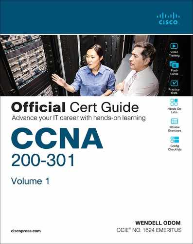
Figure 20-1 shows the relationship between the OSPF configuration commands, with the idea that the configuration creates a routing process in one part of the configuration, and then indirectly enables OSPF on each interface. The configuration does not name the interfaces on which OSPF is enabled, instead requiring IOS to apply some logic by comparing the OSPF network command to the interface ip address commands. The upcoming example discusses more about this logic.
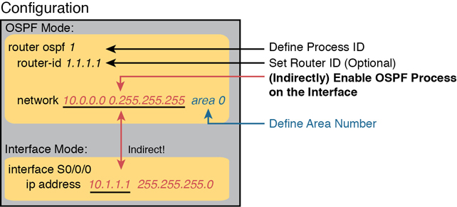
Figure 20-1 Organization of OSPFv2 Configuration with the network Command
OSPF Single-Area Configuration
Figure 20-2 shows a sample network that will be used for most examples throughout this chapter. All links reside in area 0, making the area design a single-area design, with four routers. You can think of Router R1 as a router at a central site, with WAN links to each remote site, and using router-on-a-stick (ROAS) to connect to two LAN subnets on the left. Routers R2 and R3 might be at one large remote site that needs two WAN links and two routers for WAN redundancy, with both routers connected to the LAN at that remote site. Router R4 might be a typical smaller remote site with a single router needed for that site.

Figure 20-2 Sample Network for OSPF Single-Area Configuration
Note
The interface numbering on Router R1, with interfaces G0/0 and G0/0/0, may seem a bit strange. However, real routers, like the Cisco 2901 used in the example, use this numbering. That model includes a built-in Gi0/0 and Gi0/1 port. Additionally, if you add one-port Gigabit WAN Interface Cards (WICs), the router numbers them G0/0/0, G0/1/0, and so on. This is just one example of how router hardware may use two-digit interface numbering, or three-digit, or both.
Example 20-1 shows the IPv4 addressing configuration on Router R1, before getting into the OSPF detail. Note that R1 enables 802.1Q trunking (ROAS) on its G0/0 interface and assigns an IP address to each subinterface.
Example 20-1 IPv4 Address Configuration on R1 (Including VLAN Trunking)
interface GigabitEthernet0/0.1
 encapsulation dot1q 1 native
 ip address 10.1.1.1 255.255.255.0
!
interface GigabitEthernet0/0.2
 encapsulation dot1q 2
 ip address 10.1.2.1 255.255.255.0
!
interface GigabitEthernet0/0/0
 ip address 10.1.12.1 255.255.255.0
!
interface GigabitEthernet0/1/0
 ip address 10.1.13.1 255.255.255.0
!
interface GigabitEthernet0/2/0
 ip address 10.1.14.1 255.255.255.0
The OSPF configuration begins with the router ospf process-id global command, which puts the user in OSPF configuration mode, and sets the OSPF process-id value. The process-id number just needs to be unique on the local router, allowing the router to support multiple OSPF processes in a single router by using different process IDs. (The router command uses the process-id to distinguish between the processes.) The process-id does not have to match on each router, and it can be any integer between 1 and 65,535.
Second, the configuration needs one or more network commands in OSPF mode. These commands tell the router to find its local interfaces that match the first two parameters on the network command. Then, for each matched interface, the router enables OSPF on those interfaces, discovers neighbors, creates neighbor relationships, and assigns the interface to the area listed in the network command. (Note that the area can be configured as either an integer or a dotted-decimal number, but this book makes a habit of configuring the area number as an integer. The integer area numbers range from 0 through 4,294,967,295.)
Example 20-2 shows an example configuration on router R2 from Figure 20-2. The router ospf 1 command enables OSPF process 1, and the single network command enables OSPF on all interfaces shown in the figure.
Example 20-2 OSPF Single-Area Configuration on R2 Using One network Command
router ospf 1
 network 10.0.0.0 0.255.255.255 area 0
For the specific network command in Example 20-2, any matched interfaces are assigned to area 0. However, the first two parameters—the ip_address and wildcard_mask parameter values of 10.0.0.0 and 0.255.255.255—need some explaining. In this case, the command matches both interfaces shown for Router R2; the next topic explains why.
Wildcard Matching with the network Command
The key to understanding the traditional OSPFv2 configuration shown in this first example is to understand the OSPF network command. The OSPF network command compares the first parameter in the command to each interface IP address on the local router, trying to find a match. However, rather than comparing the entire number in the network command to the entire IPv4 address on the interface, the router can compare a subset of the octets, based on the wildcard mask, as follows:

Wildcard 0.0.0.0: Compare all four octets. In other words, the numbers must exactly match.
Wildcard 0.0.0.255: Compare the first three octets only. Ignore the last octet when comparing the numbers.
Wildcard 0.0.255.255: Compare the first two octets only. Ignore the last two octets when comparing the numbers.
Wildcard 0.255.255.255: Compare the first octet only. Ignore the last three octets when comparing the numbers.
Wildcard 255.255.255.255: Compare nothing; this wildcard mask means that all addresses will match the network command.
Basically, a wildcard mask value of decimal 0 in an octet tells IOS to compare to see if the numbers match, and a value of 255 tells IOS to ignore that octet when comparing the numbers.
The network command provides many flexible options because of the wildcard mask. For example, in Router R1, many network commands could be used, with some matching all interfaces, and some matching a subset of interfaces. Table 20-2 shows a sampling of options, with notes.
Table 20-2 Example OSPF network Commands on R3, with Expected Results
Command |
Logic in Command |
Matched Interfaces |
|---|---|---|
network 10.1.0.0 0.0.255.255 |
Match addresses that begin with 10.1 |
G0/0.1 G0/0.2 G0/0/0 G0/1/0 G0/2/0 |
network 10.0.0.0 0.255.255.255 |
Match addresses that begin with 10 |
G0/0.1 G0/0.2 G0/0/0 G0/1/0 G0/2/0 |
network 0.0.0.0 255.255.255.255 |
Match all addresses |
G0/0.1 G0/0.2 G0/0/0 G0/1/0 G0/2/0 |
network 10.1.13.0 0.0.0.255 |
Match addresses that begin with 10.1.13 |
G0/1/0 |
network 10.1.13.1 0.0.0.0 |
Match one address: 10.1.13.1 |
G0/1/0 |
The wildcard mask gives the local router its rules for matching its own interfaces. To show examples of the different options, Example 20-3 shows the configuration on routers R2, R3, and R4, each using different wildcard masks. Note that all three routers (R2, R3, and R4) enable OSPF on all the interfaces shown in Figure 20-2.
Example 20-3 OSPF Configuration on Routers R2, R3, and R4
! R2 configuration next - one network command enables OSPF on both interfaces
interface GigabitEthernet0/0
 ip address 10.1.23.2 255.255.255.0
!
interface GigabitEthernet0/1/0
 ip address 10.1.12.2 255.255.255.0
!
router ospf 1
 network 10.0.0.0 0.255.255.255 area 0
! R3 configuration next - One network command per interface
interface GigabitEthernet0/0
 ip address 10.1.23.3 255.255.255.0
!
interface GigabitEthernet0/0/0
 ip address 10.1.13.3 255.255.255.0
!
router ospf 1
 network 10.1.13.3 0.0.0.0 area 0
 network 10.1.23.3 0.0.0.0 area 0
! R4 configuration next - One network command per interface with wildcard 0.0.0.255
interface GigabitEthernet0/1
 ip address 10.1.4.4 255.255.255.0
!
interface GigabitEthernet0/0/0
 ip address 10.1.14.4 255.255.255.0
!
router ospf 1
 network 10.1.14.0 0.0.0.255 area 0
 network 10.1.4.0 0.0.0.255 area 0
Finally, note that OSPF uses the same wildcard mask logic as defined by Cisco IOS access control lists. The section titled “Finding the Right Wildcard Mask to Match a Subnet” section in Chapter 2 of the CCNA 200-301 Official Cert Guide, Volume 2, provides more detail about wildcard masks.
Note
IOS will change a network command if it does not follow a particular rule: by convention, if the wildcard mask octet is 255, the matching address octet should be configured as a 0. Interestingly, IOS will actually accept a network command that breaks this rule, but then IOS will change that octet of the address to a 0 before putting it into the running configuration file. For example, IOS will change a typed command that begins with network 1.2.3.4 0.0.255.255 to network 1.2.0.0 0.0.255.255.
Verifying OSPF Operation
As mentioned in Chapter 19, “Understanding OSPF Concepts,” OSPF routers use a three-step process to eventually add OSPF-learned routes to the IP routing table. First, they create neighbor relationships. Then they build and flood LSAs between those neighbors so each router in the same area has a copy of the same LSDB. Finally, each router independently computes its own IP routes using the SPF algorithm and adds them to its routing table. This next topic works through how to display the results of each of those steps, which lets you confirm whether OSPF has worked correctly or not.
The show ip ospf neighbor, show ip ospf database, and show ip route commands display information to match each of these three steps, respectively. Figure 20-3 summarizes the commands you can use (and others) when verifying OSPF.

Figure 20-3 OSPF Verification Commands
Many engineers begin OSPF verification by looking at the output of the show ip ospf neighbor command. For instance, Example 20-4 shows a sample from Router R1, which should have one neighbor relationship each with routers R2, R3, and R4. Example 20-4 shows all three.

Example 20-4 OSPF Neighbors on Router R1 from Figure 20-2
R1# show ip ospf neighbor
Neighbor ID     Pri   State          Dead Time   Address       Interface
2.2.2.2           1   FULL/DR        00:00:37    10.1.12.2     GigabitEthernet0/0/0
3.3.3.3           1   FULL/DR        00:00:37    10.1.13.3     GigabitEthernet0/1/0
4.4.4.4           1   FULL/BDR       00:00:34    10.1.14.4     GigabitEthernet0/2/0
The detail in the output mentions several important facts, and for most people, working right to left works best in this case. For example, look at the headings:
Interface: This is the local router’s interface connected to the neighbor. For example, the first neighbor in the list is reachable through R1’s G0/0/0 interface.
Address: This is the neighbor’s IP address on that link. Again, for this first neighbor, which is R1, uses IP address 10.1.13.1.
State: While many possible states exist, for the details discussed in this chapter, FULL is the correct and fully working state in this case.
Neighbor ID: This is the router ID of the neighbor.
Once OSPF convergence has completed, a router should list each neighbor. On links that use a designated router (DR), the state will also list the role of the neighboring router after the / (DR, BDR, or DROTHER. As a result, the normal working states will be:
FULL/ -: The neighbor state is full, with the “-“ instead of letters meaning that the link does not use a DR/BDR.
FULL/DR: The neighbor state is full, and the neighbor is the DR.
FULL/BDR: The neighbor state is full, and the neighbor is the backup DR (BDR).
FULL/DROTHER: The neighbor state is full, and the neighbor is neither the DR nor BDR. (It also implies that the local router is a DR or BDR because the state is FULL.)
2WAY/DROTHER: The neighbor state is 2-way, and the neighbor is neither the DR nor BDR—that is, a DROther router. (It also implies that the local router is also a DROther router because otherwise the state would reach a full state.)
Once a router’s OSPF process forms a working neighbor relationship, the routers exchange the contents of their LSDBs, either directly or through the DR on the subnet. Example 20-5 shows the contents of the LSDB on Router R1. Interestingly, with a single-area design, all the routers will have the same LSDB contents once all neighbors are up and all LSAs have been exchanged. So, the show ip ospf database command in Example 20-5 should list the same exact information, no matter on which of the four routers it is issued.
Example 20-5 OSPF Database on Router R1 from Figure 20-2
R1# show ip ospf database

            OSPF Router with ID (1.1.1.1) (Process ID 1)

                 Router Link States (Area 0)

Link ID         ADV Router      Age         Seq#       Checksum Link count
1.1.1.1         1.1.1.1         431         0x8000008F 0x00DCCA 5
2.2.2.2         2.2.2.2         1167        0x8000007F 0x009DA1 2
3.3.3.3         3.3.3.3         441         0x80000005 0x002FB1 1
4.4.4.4         4.4.4.4         530         0x80000004 0x007F39 2

                Net Link States (Area 0)

Link ID         ADV Router      Age         Seq#       Checksum
10.1.12.2       2.2.2.2         1167        0x8000007C 0x00BBD5
10.1.13.3       3.3.3.3         453         0x80000001 0x00A161
10.1.14.1       1.1.1.1         745         0x8000007B 0x004449
10.1.23.3       3.3.3.3         8           0x80000001 0x00658F
For the purposes of this book, do not be concerned about the specifics in the output of this command. However, for perspective, note that the LSDB should list one “Router Link State” (Type 1 Router LSA) for each of the routers in the same area, so with the design based on Figure 20-2, the output lists four Type 1 LSAs. Also, with all default settings in this design, the routers will create a total of four Type 2 Network LSAs as shown, one each for the subnets that have a DR and contain at least two routers in that subnet.
Next, Example 20-6 shows R4’s IPv4 routing table with the show ip route command. As configured, with all links working, the design in Figure 20-2 includes seven subnets. R4 has connected routes to two of those subnets and should learn OSPF routes to the other five subnets.
Example 20-6 IPv4 Routes Added by OSPF on Router R1 from Figure 20-2
R4# show ip route
Codes: L - local, C - connected, S - static, R - RIP, M - mobile, B - BGP
       D - EIGRP, EX - EIGRP external, O - OSPF, IA - OSPF inter area
       N1 - OSPF NSSA external type 1, N2 - OSPF NSSA external type 2
       E1 - OSPF external type 1, E2 - OSPF external type 2
! Additional legend lines omitted for brevity

Gateway of last resort is not set

      10.0.0.0/8 is variably subnetted, 9 subnets, 2 masks
O        10.1.1.0/24 [110/2] via 10.1.14.1, 00:27:24, GigabitEthernet0/0/0
O        10.1.2.0/24 [110/2] via 10.1.14.1, 00:27:24, GigabitEthernet0/0/0
C        10.1.4.0/24 is directly connected, Vlan4
L        10.1.4.4/32 is directly connected, Vlan4
O        10.1.12.0/24 [110/2] via 10.1.14.1, 00:27:24, GigabitEthernet0/0/0
O        10.1.13.0/24 [110/2] via 10.1.14.1, 00:25:15, GigabitEthernet0/0/0
C        10.1.14.0/24 is directly connected, GigabitEthernet0/0/0
L        10.1.14.4/32 is directly connected, GigabitEthernet0/0/0
O        10.1.23.0/24 [110/3] via 10.1.14.1, 00:27:24, GigabitEthernet0/0/0
Any time you want to check OSPF on a router in a small design like the ones in the book, you can count all the subnets, then count the subnets connected to the local router, and know that OSPF should learn routes to the rest of the subnets. Then just use the show ip route command and add up how many connected and OSPF routes exist as a quick check of whether all the routes have been learned or not.
In this case, router R4 has two connected subnets, but seven subnets exist per the figure, so router R4 should learn five OSPF routes. Next look for the code of “O” on the left, which identifies a route as being learned by OSPF. The output lists five such IP routes: two for the LAN subnets off Router R1, one for the LAN subnets connected to both R2 and R3, and one each for the WAN subnets from R1 to R2 and R1 to R3.
Next, take a look at the first route (to subnet 10.1.1.0/24). It lists the subnet ID and mask, identifying the subnet. It also lists two numbers in brackets. The first, 110, is the administrative distance of the route. All the OSPF routes in this example use the default of 110 (see Chapter 19’s Table 19-4 for the list of administrative distance values). The second number, 2, is the OSPF metric for this route. The route also lists the forwarding instructions: the next-hop IP address (10.1.14.1) and R4’s outgoing interface (G0/0/0).
Verifying OSPF Configuration
Once you can configure OSPF with confidence, you will likely verify OSPF focusing on OSPF neighbors and the IP routing table as just discussed. However, if OSPF does not work immediately, you may need to circle back and check the configuration. To do so, you can use these steps:
If you have enable mode access, use the show running-config command to examine the configuration.
If you have only user mode access, use the show ip protocols command to re-create the OSPF configuration.
Use the show ip ospf interface [brief] command to determine whether the router enabled OSPF on the correct interfaces or not based on the configuration.
Note
The exam’s Sim and Simlet questions can restrict access to enable mode, so knowing how to extract the configuration from show commands other than show running-config can be particularly helpful for any configuration topic.
The best way to verify the configuration begins with the show running-config command, of course. However, the show ip protocols command repeats the details of the OSPFv2 configuration and does not require enable mode access. To see how, consider Example 20-7, which lists the output of the show ip protocols command on router R3.
Example 20-7 Router R3 Configuration and the show ip protocols Command
! First, a reminder of R3's configuration per Example 20-3:
router ospf 1
 network 10.1.13.3 0.0.0.0 area 0
 network 10.1.23.3 0.0.0.0 area 0
!
! The output from router R3:
R3# show ip protocols
*** IP Routing is NSF aware ***

Routing Protocol is "ospf 1"
  Outgoing update filter list for all interfaces is not set
  Incoming update filter list for all interfaces is not set
  Router ID 3.3.3.3
  Number of areas in this router is 1. 1 normal 0 stub 0 nssa
  Maximum path: 4
  Routing for Networks:
    10.1.13.3 0.0.0.0 area 0
    10.1.23.3 0.0.0.0 area 0
  Routing Information Sources:
    Gateway         Distance      Last Update
    1.1.1.1              110      02:05:26
    4.4.4.4              110      02:05:26
    2.2.2.2              110      01:51:16
  Distance: (default is 110)
The highlighted output emphasizes some of the configuration. The first highlighted line repeats the parameters on the router ospf 1 global configuration command. (The second highlighted item points out each router’s router ID, which will be discussed in the next section.) The third set of highlighted lines begins with a heading of “Routing for Networks:” followed by two lines that closely resemble the parameters on the configured network commands. In fact, closely compare those last two highlighted lines with the network configuration commands at the top of the example, and you will see that they mirror each other, but the show command just leaves out the word network. For instance:
Configuration: network 10.1.13.3 0.0.0.0 area 0
Show Command: 10.1.13.3 0.0.0.0 area 0
IOS interprets the network commands to choose interfaces on which to run OSPF, so it could be that IOS chooses a different set of interfaces than you predicted. To check the list of interfaces chosen by IOS, use the show ip ospf interface brief command, which lists all interfaces that have been enabled for OSPF processing. Verifying the interfaces can be a useful step if you have issues with OSPF neighbors because OSPF must first be enabled on an interface before a router will attempt to discover neighbors on that interface. Example 20-8 shows a sample from Router R1.
Example 20-8 Router R1 show ip ospf interface brief Command
R1# show ip ospf interface brief
Interface    PID   Area            IP Address/Mask    Cost  State Nbrs F/C
Gi0/0/0      1     0               10.1.12.1/24       1     BDR   1/1
Gi0/1/0      1     0               10.1.13.1/24       1     BDR   1/1
Gi0/2/0      1     0               10.1.14.1/24       1     DR    1/1
Gi0/0.2      1     0               10.1.2.1/24        1     DR    0/0
Gi0/0.1      1     0               10.1.1.1/24        1     DR    0/0
First, consider the show ip ospf interface brief command shown here. It lists one line per interface, with the list showing all the interfaces on which OSPF has been enabled. Each item in the list identifies the OSPF process ID (per the router ospf process-id command), the area, the interface IP address, and the number of neighbors found via each interface.
More generally, note that the show ip ospf interface command with the brief keyword at the end lists a single line of output per interface, but the show ip ospf interface command (without the brief keyword) displays about 20 lines of output per interface, with much more information about various OSPF per-interface settings.
Configuring the OSPF Router ID
While OSPF has many other optional features, most enterprise networks that use OSPF choose to configure each router’s OSPF router ID. OSPF-speaking routers must have a router ID (RID) for proper operation. By default, routers will choose an interface IP address to use as the RID. However, many network engineers prefer to choose each router’s router ID, so command output from commands like show ip ospf neighbor lists more recognizable router IDs.
To choose its RID, a Cisco router uses the following process when the router reloads and brings up the OSPF process. Note that the router stops looking for a router ID to use once one of the steps identifies a value to use.
If the router-id rid OSPF subcommand is configured, this value is used as the RID.
If any loopback interfaces have an IP address configured, and the interface has an interface status of up, the router picks the highest numeric IP address among these loopback interfaces.
The router picks the highest numeric IP address from all other interfaces whose interface status code (first status code) is up. (In other words, an interface in up/down state will be included by OSPF when choosing its router ID.)
The first and third criteria should make some sense right away: the RID is either configured or is taken from a working interface’s IP address. However, this book has not yet explained the concept of a loopback interface, as mentioned in Step 2.
A loopback interface is a virtual interface that can be configured with the interface loopback interface-number command, where interface-number is an integer. Loopback interfaces are always in an “up and up” state unless administratively placed in a shutdown state. For example, a simple configuration of the command interface loopback 0, followed by ip address 2.2.2.2 255.255.255.0, would create a loopback interface and assign it an IP address. Because loopback interfaces do not rely on any hardware, these interfaces can be up/up whenever IOS is running, making them good interfaces on which to base an OSPF RID.
Example 20-9 shows the configuration that existed in Routers R1 and R2 before the creation of the show command output earlier in this chapter. R1 set its router ID using the direct method, while R2 used a loopback IP address.
Example 20-9 OSPF Router ID Configuration Examples
! R1 Configuration first
router ospf 1
 router-id 1.1.1.1
 network 10.1.0.0 0.0.255.255 area 0
! R2 Configuration next
!
interface Loopback2
 ip address 2.2.2.2 255.255.255.255
Each router chooses its OSPF RID when OSPF is initialized, which happens when the router boots or when a CLI user stops and restarts the OSPF process (with the clear ip ospf process command). So, if OSPF comes up, and later the configuration changes in a way that would impact the OSPF RID, OSPF does not change the RID immediately. Instead, IOS waits until the next time the OSPF process is restarted.
Example 20-10 shows the output of the show ip ospf command on R1, which identifies the OSPF RID used by R1.
Example 20-10 Confirming the Current OSPF Router ID
R1# show ip ospf
 Routing Process "ospf 1" with ID 1.1.1.1
! lines omitted for brevity
Implementing Multiarea OSPF
Even though the current CCNA 200-301 exam blueprint mentions single-area OSPF and does not mention multiarea OSPF, you only need to learn one more idea to know how to configure multiarea OSPF. So, this chapter takes a brief page to show how.
For example, consider a multiarea OSPF design as shown in Figure 20-4. It uses the same routers and IP addresses as shown earlier in Figure 20-2, on which all the examples in this chapter have been based so far. However, the design shows three areas instead of the single-area design shown in Figure 20-2.
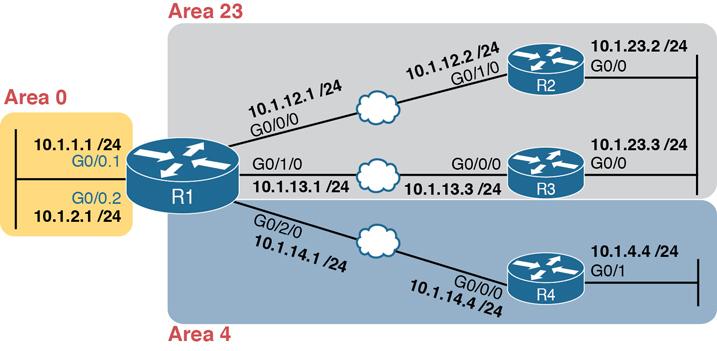
Figure 20-4 Area Design for an Example Multiarea OSPF Configuration
Configuring the routers in a multiarea design is almost like configuring OSPFv2 for a single area. To configure multiarea OSPF, all you need is a valid OSPF area design (for instance, like Figure 20-4) and a configuration that places each router interface into the correct area per that design. For example, both of R4’s interfaces connect to links in area 4, making R4 an internal router, so any network commands on router R4 will list area 4.
Example 20-11 shows a sample configuration for Router R1. To make the configuration clear, it uses network commands with a wildcard mask of 0.0.0.0, meaning each network command matches a single interface. Each interface will be placed into either area 0, 23, or 4 to match the figure.
Example 20-11 OSPF Configuration on R1, Placing Interfaces into Different Areas
router ospf 1
 network 10.1.1.1 0.0.0.0 area 0
 network 10.1.2.1 0.0.0.0 area 0
 network 10.1.12.1 0.0.0.0 area 23
 network 10.1.13.1 0.0.0.0 area 23
 network 10.1.14.1 0.0.0.0 area 4
Using OSPFv2 Interface Subcommands
From the earliest days of OSPFv2 support in Cisco routers, the configuration used the OSPF network command as discussed in this chapter. However, that configuration style can be confusing, and it does require some interpretation of the network commands and interface IP addresses to decide on which interfaces IOS will enable OSPF. As a result, Cisco added another option for OSPFv2 configuration called OSPF interface configuration.
The newer interface-style OSPF configuration still enables OSPF on interfaces, but it does so directly with the ip ospf interface subcommand instead of using the network command in router configuration mode. Basically, instead of matching interfaces with indirect logic using network commands, you directly enable OSPFv2 on interfaces by configuring an interface subcommand on each interface.
OSPF Interface Configuration Example
To show how OSPF interface configuration works, this example basically repeats the example shown earlier in the book using the traditional OSPFv2 configuration with network commands. So, before looking at the OSPFv2 interface configuration, take a moment to look back to review traditional OSPFv2 configuration with Figure 20-2 and Examples 20-2 and 20-3.
After reviewing the traditional configuration, consider this checklist, which details how to convert from the old-style configuration in Examples 20-2 and 20-3 to use interface configuration:
Step 1. Use the no network network-id area area-id subcommands in OSPF configuration mode to remove the network commands.
Step 2. Add one ip ospf process-id area area-id command in interface configuration mode under each interface on which OSPF should operate, with the correct OSPF process (process-id) and the correct OSPF area number.
Figure 20-5 repeats the design for both the original examples in this chapter and for this upcoming interface configuration example.
Figure 20-5 Area Design Used in the Upcoming OSPF Interface Config Example
Example 20-2 shows a single network command: network 10.0.0.0 0.255.255.255 area 0. Example 20-12 follows the steps in the migration checklist, beginning with the removal of the previous configuration using the no network 10.0.0.0 0.255.255.255 area 0 command. The example then shows the addition of the ip ospf 1 area 0 command on each of the five interfaces on Router R1, enabling OSPF process 1 on the interface and placing each interface into area 0.
Example 20-12 OSPF Single-Area Configuration on R1 Using One network Command
R1# configure terminal
Enter configuration commands, one per line.  End with CNTL/Z.
R1(config)# router ospf 1
R1(config-router)# no network 10.0.0.0 0.255.255.255 area 0
R1(config-router)#
*Apr  8 19:35:24.994: %OSPF-5-ADJCHG: Process 1, Nbr 2.2.2.2 on GigabitEthernet0/0/0
  from FULL to DOWN, Neighbor Down: Interface down or detached
*Apr  8 19:35:24.994: %OSPF-5-ADJCHG: Process 1, Nbr 3.3.3.3 on GigabitEthernet0/1/0
  from FULL to DOWN, Neighbor Down: Interface down or detached
*Apr  8 19:35:24.994: %OSPF-5-ADJCHG: Process 1, Nbr 4.4.4.4 on GigabitEthernet0/2/0
  from FULL to DOWN, Neighbor Down: Interface down or detached
R1(config-router)# interface g0/0.1
R1(config-subif)# ip ospf 1 area 0
R1(config-subif)# interface g0/0.2
R1(config-subif)# ip ospf 1 area 0
R1(config-subif)# interface g0/0/0
R1(config-if)# ip ospf 1 area 0
R1(config-if)#
*Apr  8 19:35:52.970: %OSPF-5-ADJCHG: Process 1, Nbr 2.2.2.2 on GigabitEthernet0/0/0
  from LOADING to FULL, Loading Done
R1(config-if)# interface g0/1/0
R1(config-if)# ip ospf 1 area 0
R1(config-if)#
*Apr  8 19:36:13.362: %OSPF-5-ADJCHG: Process 1, Nbr 3.3.3.3 on GigabitEthernet0/1/0
 from LOADING to FULL, Loading Done
R1(config-if)# interface g0/2/0
R1(config-if)# ip ospf 1 area 0
R1(config-if)#
*Apr  8 19:37:05.398: %OSPF-5-ADJCHG: Process 1, Nbr 4.4.4.4 on GigabitEthernet0/2/0
  from LOADING to FULL, Loading Done
R1(config-if)#
When reading the example, read from top to bottom, and also consider the details about the failed and recovered neighbor relationships shown in the log messages. Removing the network command disabled OSPF on all interfaces on Router R1, causing all three neighbor relationships to fail. The example then shows the addition of the ip ospf 1 area 0 command on the two LAN subinterfaces, which enables OSPF. Then the example shows the same command added to each of the WAN links in succession, and in each case, the OSPF neighbor available over that WAN link comes up (as noted in the log messages.)
Verifying OSPF Interface Configuration
OSPF operates the same way whether you use the new style or old style of configuration. The OSPF area design works the same, neighbor relationships form the same way, routers negotiate to become the DR and BDR the same way, and so on. However, you can see a few small differences in show command output when using the newer OSPFv2 configuration if you look closely.
The show ip protocols command relists most of the routing protocol configuration, so it does list some different details if you use interface configuration versus the network command. With the newer-style configuration, the output lists the phrase “Interfaces Configured Explicitly,” with the list of interfaces configured with the new ip ospf process-id area area-id commands, as highlighted in Example 20-13. The example first shows the relevant parts of the show ip protocols command when using interface configuration on Router R1, and then lists the same portions of the command from when R1 used network commands.
Example 20-13 Differences in show ip protocols Output: Old- and New-Style OSPFv2 Configuration
! First, with the new interface configuration
R1# show ip protocols
! … beginning lines omitted for brevity
  Routing for Networks:
  Routing on Interfaces Configured Explicitly (Area 0):
    GigabitEthernet0/2/0
    GigabitEthernet0/1/0
    GigabitEthernet0/0/0
    GigabitEthernet0/0.2
    GigabitEthernet0/0.1
  Routing Information Sources:
    Gateway         Distance      Last Update
    4.4.4.4              110      00:09:30
    2.2.2.2              110      00:10:49
    3.3.3.3              110      05:20:07
  Distance: (default is 110)
! For comparison, the old results with the use of the OSPF network command
R1# show ip protocols
! … beginning lines omitted for brevity
  Routing for Networks:
    10.1.0.0 0.0.255.255 area 0
! … ending line omitted for brevity
Another small piece of different output exists in the show ip ospf interface [interface] command. The command lists details about OSPF settings for the interface(s) on which OSPF is enabled. The output also makes a subtle reference to whether that interface was enabled for OSPF with the old or new configuration style. Example 20-14 also begins with output based on interface configuration on Router R1, followed by the output that would exist if R1 still used the old-style network command.
Example 20-14 Differences in show ip ospf interface Output with OSPFv2 Interface Configuration
! First, with the new interface configuration
R1# show ip ospf interface g0/0/0
GigabitEthernet0/0/0 is up, line protocol is up
  Internet Address 10.1.12.1/24, Area 0, Attached via Interface Enable
! Lines omitted for brevity
! For comparison, the old results with the use of the OSPF network command
R1# show ip ospf interface g0/0/0
GigabitEthernet0/0/0 is up, line protocol is up
  Internet Address 10.1.12.1/24, Area 0, Attached via Network Statement
! … ending line omitted for brevity
Other than these small differences in a few show commands, the rest of the commands show nothing different depending on the style of configuration. For instance, the show ip ospf interface brief command does not change depending on the configuration style, nor do the show ip ospf database, show ip ospf neighbor, or show ip route commands.
Additional OSPFv2 Features
This final major section of the chapter discusses some very popular but optional OSPFv2 configuration features, as listed here in their order of appearance:
Passive interfaces
Default routes
Metrics
Load balancing
OSPF Passive Interfaces
Once OSPF has been enabled on an interface, the router tries to discover neighboring OSPF routers and form a neighbor relationship. To do so, the router sends OSPF Hello messages on a regular time interval (called the Hello Interval). The router also listens for incoming Hello messages from potential neighbors.
Sometimes, a router does not need to form neighbor relationships with neighbors on an interface. Often, no other routers exist on a particular link, so the router has no need to keep sending those repetitive OSPF Hello messages. In such cases, an engineer can make the interface passive, which means
OSPF continues to advertise about the subnet that is connected to the interface.
OSPF no longer sends OSPF Hellos on the interface.
OSPF no longer processes any received Hellos on the interface.
The result of enabling OSPF on an interface but then making it passive is that OSPF still advertises about the connected subnet, but OSPF also does not form neighbor relationships over the interface.
To configure an interface as passive, two options exist. First, you can add the following command to the configuration of the OSPF process, in router configuration mode:
passive-interface type number
Alternately, the configuration can change the default setting so that all interfaces are passive by default and then add a no passive-interface command for all interfaces that need to not be passive:
passive-interface default
no passive-interface type number
For example, in the sample internetwork in Figure 20-2 (and in Figure 20-5), Router R1, on the left side of the figure, has a LAN interface configured for VLAN trunking. The only router connected to both VLANs is Router R1, so R1 will never discover an OSPF neighbor on these subnets. Example 20-15 shows two alternative configurations to make the two LAN subinterfaces passive to OSPF.
Example 20-15 Configuring Passive Interfaces on R1 from Figure 20-5
! First, make each subinterface passive directly
router ospf 1
 passive-interface GigabitEthernet0/0.1
 passive-interface GigabitEthernet0/0.2

! Or, change the default to passive, and make the other interfaces not be passive
router ospf 1
 passive-interface default
 no passive-interface GigabitEthernet0/0/0
 no passive-interface GigabitEthernet0/1/0
 no passive-interface GigabitEthernet0/2/0
In real internetworks, the choice of configuration style reduces to which option requires the least number of commands. For example, a router with 20 interfaces, 18 of which are passive to OSPF, has far fewer configuration commands when using the passive-interface default command to change the default to passive. If only two of those 20 interfaces need to be passive, use the default setting, in which all interfaces are not passive, to keep the configuration shorter.
Interestingly, OSPF makes it a bit of a challenge to use show commands to find whether or not an interface is passive. The show running-config command lists the configuration directly, but if you cannot get into enable mode to use this command, note these two facts:
The show ip ospf interface brief command lists all interfaces on which OSPF is enabled, including passive interfaces.
The show ip ospf interface command lists a single line that mentions that the interface is passive.
Example 20-16 shows these two commands on Router R1, based on the configuration shown in the top of Example 20-15. Note that subinterfaces G0/0.1 and G0/0.2 both show up in the output of show ip ospf interface brief.
Example 20-16 Displaying Passive Interfaces
R1# show ip ospf interface brief
Interface                  IP-Address      OK? Method Status                Protocol
GigabitEthernet0/0         unassigned      YES manual up                    up
GigabitEthernet0/0.1       10.1.1.1        YES manual up                    up
GigabitEthernet0/0.2       10.1.2.1        YES manual up                    up
GigabitEthernet0/1         unassigned      YES manual administratively down down
GigabitEthernet0/0/0       10.1.12.1       YES manual up                    up
GigabitEthernet0/1/0       10.1.13.1       YES manual up                    up
GigabitEthernet0/2/0       10.1.14.1       YES manual up                    up

R1# show ip ospf interface g0/0.1
GigabitEthernet0/0.1 is up, line protocol is up
  Internet Address 10.1.1.1/24, Area 0, Attached via Network Statement
  Process ID 1, Router ID 1.1.1.1, Network Type BROADCAST, Cost: 1
  Topology-MTID    Cost    Disabled    Shutdown      Topology Name
        0           1         no          no            Base
  Transmit Delay is 1 sec, State DR, Priority 1
  Designated Router (ID) 1.1.1.1, Interface address 10.1.1.1
  No backup designated router on this network
  Timer intervals configured, Hello 10, Dead 40, Wait 40, Retransmit 5
    oob-resync timeout 40
    No Hellos (Passive interface)
! Lines omitted for brevity
OSPF Default Routes
Chapter 16, “Configuring IPv4 Addressing and Static Routes,” showed some of the uses and benefits of default routes, with examples of static default routes. For those exact same reasons, networks can use OSPF to advertise default routes.
The most classic case for using a routing protocol to advertise a default route has to do with an enterprise’s connection to the Internet. As a strategy, the enterprise engineer uses these design goals:
All routers learn specific (nondefault) routes for subnets inside the company; a default route is not needed when forwarding packets to these destinations.
One router connects to the Internet, and it has a default route that points toward the Internet.
All routers should dynamically learn a default route, used for all traffic going to the Internet, so that all packets destined to locations in the Internet go to the one router connected to the Internet.
Figure 20-6 shows the idea of how OSPF advertises the default route, with the specific OSPF configuration. In this case, a company connects to an ISP with its Router R1. That router has a static default route (destination 0.0.0.0, mask 0.0.0.0) with a next-hop address of the ISP router. Then the use of the OSPF default-information originate command (Step 2) makes the router advertise a default route using OSPF to the remote routers (B1 and B2).
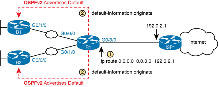
Figure 20-6 Using OSPF to Create and Flood a Default Route
Figure 20-7 shows the default routes that result from OSPF’s advertisements in Figure 20-6. On the far left, the branch routers all have OSPF-learned default routes, pointing to R1. R1 itself also needs a default route, pointing to the ISP router, so that R1 can forward all Internet-bound traffic to the ISP.
Finally, this feature gives the engineer control over when the router originates this default route. First, R1 needs a default route, either defined as a static default route, learned from the ISP with DHCP or learned from the ISP with a routing protocol like eBGP. The OSPF subcommand default-information originate then tells OSPF on R1 to advertise a default route when its own default route is working and to advertise the default route as down when its own default route fails.
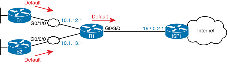
Figure 20-7 Default Routes Resulting from the default-information originate Command
Note
Interestingly, the default-information originate always router subcommand tells the router to always advertise the default route, no matter whether the router’s default route is working or not.
Example 20-17 shows details of the default route on both R1 and branch router B1 from Figure 20-7. R1 then creates a static default route with the ISP router’s IP address of 192.0.2.1 as the next-hop address, as highlighted in the output of the show ip route static command output.
Example 20-17 Default Routes on Routers R1 and B1
! The next command is from Router R1. Note the static code for the default route
R1# show ip route static
Codes: L - local, C - connected, S - static, R - RIP, M - mobile, B - BGP
! Rest of the legend omitted for brevity

Gateway of last resort is 192.0.2.1 to network 0.0.0.0

S*     0.0.0.0/0 [254/0] via 192.0.2.1
! The next command is from router B01; notice the External route code for the default
B1# show ip route ospf
Codes: L - local, C - connected, S - static, R - RIP, M - mobile, B - BGP
       D - EIGRP, EX - EIGRP external, O - OSPF, IA - OSPF inter area
       N1 - OSPF NSSA external type 1, N2 - OSPF NSSA external type 2
       E1 - OSPF external type 1, E2 - OSPF external type 2
! Rest of the legend omitted for brevity

Gateway of last resort is 10.1.12.1 to network 0.0.0.0

O*E2   0.0.0.0/0 [110/1] via 10.1.12.1, 00:20:51, GigabitEthernet0/1/0
       10.0.0.0/8 is variably subnetted, 6 subnets, 2 masks
O         10.1.3.0/24 [110/3] via 10.1.12.1, 00:20:51, GigabitEthernet0/1/0
O         10.1.13.0/24 [110/2] via 10.1.12.1, 00:20:51, GigabitEthernet0/1/0
Keeping the focus on the command on Router R1, note that R1 indeed has a default route—that is, a route to 0.0.0.0/0. The “Gateway of last resort,” which refers to the default route currently used by the router, points to next-hop IP address 192.0.2.1, which is the ISP router’s IP address. (Refer to Figure 20-7 for the particulars.)
Next look to the bottom half of the example and router B1’s OSPF-learned default route. B1 lists a route for 0.0.0.0/0 as well. The next-hop router in this case is 10.1.12.1, which is Router R1’s IP address on the WAN link. The code on the far left is O*E2, meaning an OSPF-learned route, which is a default route, and is specifically an external OSPF route. Finally, B1’s gateway of last resort setting uses that one OSPF-learned default route, with next-hop router 10.1.12.1.
OSPF Metrics (Cost)
The section “Calculating the Best Routes with SPF” in Chapter 19 discussed how SPF calculates the metric for each route, choosing the route with the best metric for each destination subnet. OSPF routers can influence that choice by changing the OSPF interface cost on any and all interfaces.
Cisco routers allow three different ways to change the OSPF interface cost:
Directly, using the interface subcommand ip ospf cost x.
Using the default calculation per interface, and changing the interface bandwidth setting, which changes the calculated value.
Using the default calculation per interface, and changing the OSPF reference bandwidth setting, which changes the calculated value.
Setting the Cost Directly
Setting the cost directly requires a simple configuration command, as shown in Example 20-18. The example sets the cost of two interfaces on Router R1. (This example uses the Figure 20-2 design, as configured in Examples 20-2 and 20-3.) The show ip ospf interface brief command that follows details the cost of each interface. Note that the show command confirms the cost settings.
Example 20-18 Confirming OSPF Interface Costs
R1# conf t
Enter configuration commands, one per line.  End with CNTL/Z.
R1(config)# interface g0/0/0
R1(config-if)# ip ospf cost 4
R1(config-if)# interface g0/1/0
R1(config-if)# ip ospf cost 5
R1(config-if)# ^Z
R1#
R1# show ip ospf interface brief
Interface    PID   Area            IP Address/Mask    Cost  State Nbrs F/C
Gi0/0.2      1     0               10.1.2.1/24        1     DR    0/0
Gi0/0.1      1     0               10.1.1.1/24        1     DR    0/0
Gi0/0/0      1     0               10.1.12.1/24       4     DR    1/1
Gi0/1/0      1     0               10.1.13.1/24       5     BDR   1/1
Gi0/2/0      1     0               10.1.14.1/24       1     DR    1/1
The output also shows a cost value of 1 for the other Gigabit interfaces, which is the default OSPF cost for any interface faster than 100 Mbps. The next topic discusses how IOS determines the default cost values.
Setting the Cost Based on Interface and Reference Bandwidth
Routers use a per-interface bandwidth setting to describe the speed of the interface. Note that the interface bandwidth setting does not influence the actual transmission speed. Instead, the interface bandwidth acts as a configurable setting to represent the speed of the interface, with the option to configure the bandwidth to match the actual transmission speed…or not. To support this logic, IOS sets a default interface bandwidth value that matches the physical transmission speed when possible, but also allows the configuration of the interface bandwidth using bandwidth speed interface subcommand.
OSPF (as well as other IOS features) uses the interface bandwidth to make decisions, with OSPF using the interface bandwidth in its calculation of the default OSPF cost for each interface. IOS uses the following formula to choose an interface’s OSPF cost if the cost for cases in which the ip ospf cost command is not configured on the interface. IOS puts the interface’s bandwidth in the denominator and an OSPF setting called the reference bandwidth in the numerator:
Reference_bandwidth / Interface_bandwidth
Note that while you can change both the interface bandwidth and reference bandwidth via configuration, because several IOS features make use of the bandwidth setting, you should avoid changing the interface bandwidth as a means to influence the default OSPF cost.
That being said, many enterprises do use default cost settings while influencing the default by changing the OSPF reference bandwidth while leaving the interface bandwidth as an accurate representation of link speed. Cisco chose the IOS default reference bandwidth setting decades ago in an era with much slower links. As a result, any interface with an interface bandwidth of 100 Mbps or faster ties with a calculated OSPF cost of 1 when using the default reference bandwidth. So, when relying on the default OSPF cost calculation, it helps to configure the reference bandwidth to another value.
To see the issue, consider Table 20-3, which lists several types of interfaces, the default interface bandwidth on those interfaces, and the OSPF cost calculated with the default OSPF reference bandwidth of 100 MBps (that is, 100,000 Kbps). (OSPF rounds up for these calculations, resulting in a lowest possible OSPF interface cost of 1.)
Table 20-3 Faster Interfaces with Equal OSPF Costs
Interface |
Interface Default Bandwidth (Kbps) |
Formula (Kbps) |
OSPF Cost |
|---|---|---|---|
Serial |
1544 Kbps |
100,000 / 1544 |
64 |
Ethernet |
10,000 Kbps |
100,000 / 10,000 |
10 |
Fast Ethernet |
100,000 Kbps |
100,000/100,000 |
1 |
Gigabit Ethernet |
1,000,000 Kbps |
100,000/1,000,000 |
1 |
10 Gigabit Ethernet |
10,000,000 Kbps |
100,000/10,000,000 |
1 |
100 Gigabit Ethernet |
100,000,000 Kbps |
100,000/100,000,000 |
1 |
As you can see from the table, with a default reference bandwidth, all interfaces from Fast Ethernet’s 100 Mbps and faster tie with their default OSPF cost. As a result, OSPF would treat a 100-Mbps link as having the same cost as a 10- or 100-Gbps link, which is probably not the right basis for choosing routes.
You can still use OSPF’s default cost calculation (and many do) just by changing the reference bandwidth with the auto-cost reference-bandwidth speed OSPF mode subcommand. This command sets a value in a unit of megabits per second (Mbps). Set the reference bandwidth value to a value at least as much as the fastest link speed in the network, but preferably higher, in anticipation of adding even faster links in the future.
For instance, in an enterprise whose fastest links are 10 Gbps (10,000 Mbps), you could set all routers to use auto-cost reference-bandwidth 10000, meaning 10,000 Mbps or 10 Gbps. In that case, by default, a 10-Gbps link would have an OSPF cost of 1, while a 1-Gbps link would have a cost of 10, and a 100-MBps link a cost of 100.
Better still, in that same enterprise, use a reference bandwidth of a faster speed than the fastest interface in the network, to allow room for higher speeds. For instance, in that same enterprise, whose fastest link is 10 Gbps, set the reference bandwidth to 40 Gbps or even 100 Gbps to be ready for future upgrades to use 40-Gbps links, or even 100-Gbps links. (For example, use the auto-cost reference-bandwidth 100000 command, meaning 100,000 Mbps or 100 Gbps.) That causes 100-Gbps links to have an OSPF cost of 1, 40-Gbps links to have a cost of 4, 10-Gbps links to have a cost of 10, and 1-Gbps links to have a cost of 100.
Note
Cisco recommends making the OSPF reference bandwidth setting the same on all OSPF routers in an enterprise network.
For convenient study, the following list summarizes the rules for how a router sets its OSPF interface costs:
Set the cost explicitly, using the ip ospf cost x interface subcommand, to a value between 1 and 65,535, inclusive.
Although it should be avoided, change the interface bandwidth with the bandwidth speed command, with speed being a number in kilobits per second (Kbps).
Change the reference bandwidth, using router OSPF subcommand auto-cost reference-bandwidth ref-bw, with a unit of megabits per second (Mbps).
OSPF Load Balancing
When a router uses SPF to calculate the metric for each of several routes to reach one subnet, one route may have the lowest metric, so OSPF puts that route in the routing table. However, when the metrics tie for multiple routes to the same subnet, the router can put multiple equal-cost routes in the routing table (the default is four different routes) based on the setting of the maximum-paths number router subcommand. For example, if an internetwork has six possible paths between some parts of the network, and the engineer wants all routes to be used, the routers can be configured with the maximum-paths 6 subcommand under router ospf.
The more challenging concept relates to how the routers use those multiple routes. A router could load balance the packets on a per-packet basis. For example, if the router has three equal-cost OSPF routes for the same subnet in the routing table, the router could send the one packet over the first route, the next packet over the second route, the next packet over the third route, and then start over with the first route for the next packet. Note that per-packet load balancing is generally a poor choice because it causes the most overhead work on the router. Alternatively, using the default (and better) method, the load balancing could be on a per-destination IP address basis.
Note that the default setting of maximum-paths varies by router platform.
Chapter Review
One key to doing well on the exams is to perform repetitive spaced review sessions. Review this chapter’s material using either the tools in the book or interactive tools for the same material found on the book’s companion website. Refer to the “Your Study Plan” element for more details. Table 20-4 outlines the key review elements and where you can find them. To better track your study progress, record when you completed these activities in the second column.
Table 20-4 Chapter Review Tracking
Review Element |
Review Date(s) |
Resource Used: |
|---|---|---|
Review key topics |
|
Book, website |
Review key terms |
|
Book, website |
Answer DIKTA questions |
|
Book, PTP |
Review Config Checklists |
|
Book, website |
Review command tables |
|
Book |
Do labs |
|
Blog |
Review All the Key Topics
Table 20-5 Key Topics for Chapter 20
Key Topic Element |
Description |
Page Number |
|---|---|---|
Organization of OSPFv2 configuration with the network command |
471 |
|
List |
Example OSPF wildcard masks and their meaning |
473 |
OSPF verification commands |
476 |
|
Example of the show ip ospf neighbor command |
476 |
|
List |
Neighbor states and their meanings |
477 |
List |
Rules for setting the router ID |
481 |
Differences in show ip ospf interface output with OSPF interface configuration |
486 |
|
List |
Actions IOS takes when an OSPF interface is passive |
487 |
Actions taken by the OSPF default-information originate command |
489 |
|
List |
Rules for setting OSPF interface cost |
493 |
Key Terms You Should Know
Command References
Tables 20-6 and 20-7 list configuration and verification commands used in this chapter. As an easy review exercise, cover the left column in a table, read the right column, and try to recall the command without looking. Then repeat the exercise, covering the right column, and try to recall what the command does.
Table 20-6 Chapter 20 Configuration Command Reference
Command |
Description |
|---|---|
router ospf process-id |
Router subcommand that enters OSPF configuration mode for the listed process. |
network ip-address wildcard-mask area area-id |
Router subcommand that enables OSPF on interfaces matching the address/wildcard combination and sets the OSPF area. |
ip ospf process-id area area-number |
Interface subcommand to enable OSPF on the interface and to assign the interface to a specific OSPF area. |
ip ospf cost interface-cost |
Interface subcommand that sets the OSPF cost associated with the interface. |
bandwidth bandwidth |
Interface subcommand that directly sets the interface bandwidth (Kbps). |
auto-cost reference-bandwidth number |
Router subcommand that tells OSPF the numerator in the Reference_bandwidth / Interface_bandwidth formula used to calculate the OSPF cost based on the interface bandwidth. |
router-id id |
OSPF command that statically sets the router ID. |
interface loopback number |
Global command to create a loopback interface and to navigate to interface configuration mode for that interface. |
maximum-paths number-of-paths |
Router subcommand that defines the maximum number of equal-cost routes that can be added to the routing table. |
passive-interface type number |
Router subcommand that makes the interface passive to OSPF, meaning that the OSPF process will not form neighbor relationships with neighbors reachable on that interface. |
passive-interface default |
OSPF subcommand that changes the OSPF default for interfaces to be passive instead of active (not passive). |
no passive-interface type number |
OSPF subcommand that tells OSPF to be active (not passive) on that interface or subinterface. |
default-information originate [always] |
OSPF subcommand to tell OSPF to create and advertise an OSPF default route, as long as the router has some default route (or to always advertise a default, if the always option is configured). |
Table 20-7 Chapter 20 EXEC Command Reference
Command |
Description |
|---|---|
show ip ospf |
Lists information about the OSPF process running on the router, including the OSPF router ID, areas to which the router connects, and the number of interfaces in each area. |
show ip ospf interface brief |
Lists the interfaces on which the OSPF protocol is enabled (based on the network commands), including passive interfaces. |
show ip ospf interface [type number] |
Lists a long section of settings, status, and counters for OSPF operation on all interfaces, or on the listed interface, including the Hello and Dead Timers. |
show ip protocols |
Shows routing protocol parameters and current timer values. |
show ip ospf neighbor [type number] |
Lists brief output about neighbors, identified by neighbor router ID, including current state, with one line per neighbor; optionally, limits the output to neighbors on the listed interface. |
show ip ospf neighbor neighbor-ID |
Lists the same output as the show ip ospf neighbor detail command, but only for the listed neighbor (by neighbor RID). |
show ip ospf database |
Lists a summary of the LSAs in the database, with one line of output per LSA. It is organized by LSA type (first type 1, then type 2, and so on). |
show ip route |
Lists all IPv4 routes. |
show ip route ospf |
Lists routes in the routing table learned by OSPF. |
show ip route ip-address mask |
Shows a detailed description of the route for the listed subnet/mask. |
clear ip ospf process |
Resets the OSPF process, resetting all neighbor relationships and also causing the process to make a choice of OSPF RID. |