Chapter 26. Fundamentals of Wireless Networks
This chapter covers the following exam topics:
1.0 Network Fundamentals
1.1 Explain the role and function of network components
1.1.d Access Points
1.11 Describe wireless principles
1.11.a Nonoverlapping Wi-Fi channels
1.11.b SSID
1.11.c RF
Wireless communication usually involves a data exchange between two devices. A wireless LAN goes even further; many devices can participate in sharing the medium for data exchanges. Wireless LANs must transmit a signal over radio frequencies (RF) to move data from one device to another. Transmitters and receivers can be fixed in consistent locations, or they can be mobile and free to move around. This chapter explains the topologies that can be used to control access to the wireless medium and provide data exchange between devices.
“Do I Know This Already?” Quiz
Take the quiz (either here or use the PTP software) if you want to use the score to help you decide how much time to spend on this chapter. The letter answers are listed at the bottom of the page following the quiz. Appendix C, found both at the end of the book as well as on the companion website, includes both the answers and explanations. You can also find both answers and explanations in the PTP testing software.
Table 26-1 “Do I Know This Already?” Foundation Topics Section-to-Question Mapping
Foundation Topics Section |
Questions |
|---|---|
Comparing Wired and Wireless Networks |
1 |
Wireless LAN Topologies |
2–4 |
Other Wireless Topologies |
5–6 |
Wireless Bands and Channels |
7–8 |
1. Wired Ethernet and Wi-Fi are based on which two IEEE standards, respectively?
a. 802.1, 802.3
b. 802.3, 802.1
c. 802.3, 802.11
d. 802.11, 802.3
2. Devices using a wireless LAN must operate in which one of the following modes?
a. Round-robin access
b. Half duplex
c. Full duplex
d. None of these answers
3. An access point is set up to offer wireless coverage in an office. Which one of the following is the correct 802.11 term for the resulting standalone network?
a. BSA
b. BSD
c. BSS
d. IBSS
4. Which one of the following is used to uniquely identify an AP and the basic service set it maintains with its associated wireless clients?
a. SSID
b. BSSID
c. Ethernet MAC address
d. Radio MAC address
5. Which one of the following can be used to provide wireless connectivity to a nonwireless device?
a. Wireless repeater
b. Workgroup bridge
c. Transparent bridge
d. Adaptive bridge
6. Which one of the following is not needed in a Cisco outdoor mesh network?
a. A BSS function
b. Ethernet cabling to each AP
c. A workgroup bridge
d. A backhaul network
7. Which of the following are frequency bands commonly used for Wi-Fi?
a. 2.5 KHz
b. 2.5 MHz
c. 5 MHz
d. 2.5 GHz
e. 5 GHz
8. Which of the following are considered to be nonoverlapping channels?
a. Channels 1, 2, and 3 in the 2.4-GHz band
b. Channels 1, 5, and 10 in the 2.4-GHz band
c. Channels 1, 6, and 11 in the 2.4-GHz band
d. Channels 40, 44, and 48 in the 5-GHz band
Answers to the “Do I Know This Already?” quiz:
1 C
2 B
3 C
4 B
5 B
6 B
7 D, E
8 C, D
Foundation Topics
Comparing Wired and Wireless Networks
In a wired network, any two devices that need to communicate with each other must be connected by a wire. (That was obvious!) The “wire” might contain strands of metal or fiber-optic material that run continuously from one end to the other. Data that passes over the wire is bounded by the physical properties of the wire. In fact, the IEEE 802.3 set of standards defines strict guidelines for the Ethernet wire itself, in addition to how devices may connect, send, and receive data over the wire.
Wired connections have been engineered with tight constraints and have few variables that might prevent successful communication. Even the type and size of the wire strands, the number of twists the strands must make around each other over a distance, and the maximum length of the wire must adhere to the standard.
Therefore, a wired network is essentially a bounded medium; data must travel over whatever path the wire or cable takes between two devices. If the cable goes around a corner or lies in a coil, the electrical signals used to carry the data must also go around a corner or around a coil. Because only two devices may connect to a wire, only those two devices may send or transmit data. Even better: the two devices may transmit data to each other simultaneously because they each have a private, direct path to each other.
Wired networks also have some shortcomings. When a device is connected by a wire, it cannot move around very easily or very far. Before a device can connect to a wired network, it must have a connector that is compatible with the one on the end of the wire. As devices get smaller and more mobile, it just is not practical to connect them to a wire.
As its name implies, a wireless network removes the need to be tethered to a wire or cable. Convenience and mobility become paramount, enabling users to move around at will while staying connected to the network. A user can (and often does) bring along many different wireless devices that can all connect to the network easily and seamlessly.
Wireless data must travel through free space, without the constraints and protection of a wire. In the free space environment, many variables can affect the data and its delivery. To minimize the variables, wireless engineering efforts must focus on two things:
Wireless devices must adhere to a common standard (IEEE 802.11).
Wireless coverage must exist in the area where devices are expected to use it.
As you study for the CCNA 200-301 exam, keep in mind that the exam is geared more toward a functional view of wireless technology. More detailed topics like RF characteristics, antenna performance, and so on are reserved for the Implementing Cisco Enterprise Network Core Technologies ENCOR 300-401 exam.
Wireless LAN Topologies
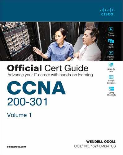
Wireless communication takes place over free space through the use of radio frequency (RF) signals. The theory behind RF signals can be complex, and is described further in the “RF Overview” section in this chapter. For now, just assume that one device, the transmitter, sends RF signals to another device, the receiver. As Figure 26-1 shows, the transmitter can contact the receiver at any and all times, as long as both devices are tuned to the same frequency (or channel) and use the same scheme to carry the data between them. That all sounds simple, except that it is not really practical.

Figure 26-1 Unidirectional Communication
To fully leverage wireless communication, data should travel in both directions, as shown in Figure 26-2. Sometimes Device A needs to send data to Device B, while Device B would like to take a turn to send at other times.
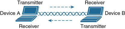
Figure 26-2 Bidirectional Communication
Because the two devices are using the same channel, two phrases in the preceding sentence become vitally important: take a turn and send at other times. With wireless communication, if multiple signals are received at the same time, they can interfere with each other. The likelihood of interference increases as the number of wireless devices grows. For example, Figure 26-3 shows four devices tuned to the same channel and what might happen if some or all of them transmit at the same time.

Figure 26-3 Interference from Simultaneous Transmissions
All this talk about waiting turns and avoiding interference might remind you of a traditional (nonswitched) Ethernet LAN, where multiple hosts can connect to a shared media and share a common bandwidth. To use the media effectively, all the hosts must operate in half-duplex mode so that they try to avoid colliding with other transmissions already in progress. The side effect is that no host can transmit and receive at the same time on a shared medium.
A wireless LAN is similar. Because multiple hosts can share the same channel, they also share the “airtime” or access to that channel at any given time. Therefore, to keep everything clean, only one device should transmit at any given time. To contend for use of the channel, devices based on the 802.11 standard have to determine whether the channel is clear and available before transmitting anything.
Note
IEEE 802.11 WLANs are always half duplex because transmissions between stations use the same frequency or channel. Only one station can transmit at any time; otherwise, collisions occur. To achieve full-duplex mode, one station’s transmission would have to occur on one frequency while it receives over a different frequency—much like full-duplex Ethernet links work. Although this is certainly possible and practical, the 802.11 standard does not permit full-duplex operation. Some amendments to the standard do provide a means for multiple devices to transmit on the same channel at the same time, but this is beyond the scope of this book.
At the most basic level, there is no inherent organization to a wireless medium or any inherent control over the number of devices that can transmit and receive frames. Any device that has a wireless network adapter can power up at any time and try to communicate. At a minimum, a wireless network should have a way to make sure that every device using a channel can support a common set of parameters. Beyond that, there should be a way to control which devices (and users) are allowed to use the wireless medium and the methods that are used to secure the wireless transmissions.
Basic Service Set
The solution is to make every wireless service area a closed group of mobile devices that forms around a fixed device; before a device can participate, it must advertise its capabilities and then be granted permission to join. The 802.11 standard calls this a basic service set (BSS). At the heart of every BSS is a wireless access point (AP), as shown in Figure 26-4. The AP operates in infrastructure mode, which means it offers the services that are necessary to form the infrastructure of a wireless network. The AP also establishes its BSS over a single wireless channel. The AP and the members of the BSS must all use the same channel to communicate properly.
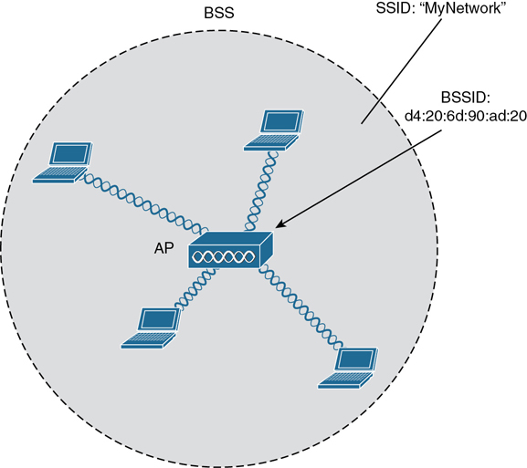
Figure 26-4 802.11 Basic Service Set
Because the operation of a BSS hinges on the AP, the BSS is bounded by the area where the AP’s signal is usable. This is known as the basic service area (BSA) or cell. In Figure 26-4, the cell is shown as a simple shaded circular area that centers around the AP itself. Cells can have other shapes too, depending on the antenna that is connected to the AP and on the physical surroundings that might affect the AP’s signals.
The AP serves as a single point of contact for every device that wants to use the BSS. It advertises the existence of the BSS so that devices can find it and try to join. To do that, the AP uses a unique BSS identifier (BSSID) that is based on the AP’s own radio MAC address.
Note
Recall that wired Ethernet devices each have a unique MAC address to send frames from a source to a destination over a Layer 2 network. Wireless devices must also have unique MAC addresses to send wireless frames at Layer 2 over the air.
In addition, the AP advertises the wireless network with a Service Set Identifier (SSID), which is a text string containing a logical name. Think of the BSSID as a machine-readable name tag that uniquely identifies the BSS ambassador (the AP), and the SSID as a nonunique, human-readable name tag that identifies the wireless service.
Membership with the BSS is called an association. A wireless device must send an association request to the AP and the AP must either grant or deny the request. Once associated, a device becomes a client, or an 802.11 station (STA), of the BSS. What then? As long as a wireless client remains associated with a BSS, most communications to and from the client must pass through the AP, as indicated in Figure 26-5. By using the BSSID as a source or destination address, data frames can be relayed to or from the AP.
Figure 26-5 Traffic Flows Within a BSS
You might be wondering why all client traffic has to traverse the AP at all. Why can two clients not simply transmit data frames directly to each other and bypass the middleman? If clients are allowed to communicate directly, then the whole idea of organizing and managing a BSS is moot. By sending data through the AP first, the BSS remains stable and under control.
Note
Even though data frames are meant to pass through an AP, keep in mind that other devices in the same general area that are listening on the same channel can overhear the transmissions. After all, wireless frames are not contained within a wire that connects a device to an AP. Instead, the frames are freely available over the air to anyone that is within range to receive them. If the frames are unencrypted, then anyone may inspect their contents. Only the BSSID value contained within the frames indicates that the intended sender or recipient is the AP.
Distribution System
Notice that a BSS involves a single AP and no explicit connection into a regular Ethernet network. In that setting, the AP and its associated clients make up a standalone network. But the AP’s role at the center of the BSS does not just stop with managing the BSS; sooner or later, wireless clients will need to communicate with other devices that are not members of the BSS. Fortunately, an AP can also uplink into an Ethernet network because it has both wireless and wired capabilities. The 802.11 standard refers to the upstream wired Ethernet as the distribution system (DS) for the wireless BSS, as shown in Figure 26-6.
You can think of an AP as a translational bridge, where frames from two dissimilar media (wireless and wired) are translated and then bridged at Layer 2. In simple terms, the AP is in charge of mapping a virtual local-area network (VLAN) to an SSID. In Figure 26-6, the AP maps VLAN 10 to the wireless LAN using SSID “MyNetwork.” Clients associated with the “MyNetwork” SSID will appear to be connected to VLAN 10.
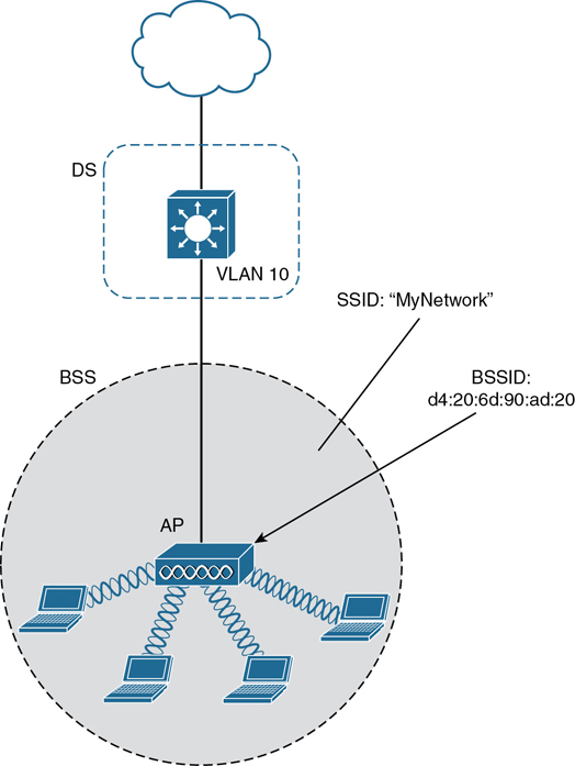
Figure 26-6 Distribution System Supporting a BSS
This concept can be extended so that multiple VLANs are mapped to multiple SSIDs. To do this, the AP must be connected to the switch by a trunk link that carries the VLANs. In Figure 26-7, VLANs 10, 20, and 30 are trunked to the AP over the DS. The AP uses the 802.1Q tag to map the VLAN numbers to the appropriate SSIDs. For example, VLAN 10 is mapped to SSID “MyNetwork,” VLAN 20 is mapped to SSID “YourNetwork,” and VLAN 30 to SSID “Guest.”


Figure 26-7 Supporting Multiple SSIDs on One AP
In effect, when an AP uses multiple SSIDs, it is trunking VLANs over the air, and over the same channel, to wireless clients. The clients must use the appropriate SSID that has been mapped to the respective VLAN when the AP was configured. The AP then appears as multiple logical APs—one per BSS—with a unique BSSID for each. With Cisco APs, this is usually accomplished by incrementing the last digit of the radio’s MAC address for each SSID.
Even though an AP can advertise and support multiple logical wireless networks, each of the SSIDs covers the same geographic area. The reason is that the AP uses the same transmitter, receiver, antennas, and channel for every SSID that it supports. Beware of one misconception though: multiple SSIDs can give an illusion of scale. Even though wireless clients can be distributed across many SSIDs, all of those clients must share the same AP’s hardware and must contend for airtime on the same channel.
Extended Service Set
Normally, one AP cannot cover the entire area where clients might be located. For example, you might need wireless coverage throughout an entire floor of a business, hotel, hospital, or other large building. To cover more area than a single AP’s cell can cover, you simply need to add more APs and spread them out geographically.
When APs are placed at different geographic locations, they can all be interconnected by a switched infrastructure. The 802.11 standard calls this an extended service set (ESS), as shown in Figure 26-8.
The idea is to make multiple APs cooperate so that the wireless service is consistent and seamless from the client’s perspective. Ideally, any SSIDs that are defined on one AP should be defined on all the APs in an ESS; otherwise, it would be very cumbersome and inconvenient for a client to be reconfigured each time it moves into a different AP’s cell.
Notice that each cell in Figure 26-8 has a unique BSSID, but both cells share one common SSID. Regardless of a client’s location within the ESS, the SSID will remain the same but the client can always distinguish one AP from another.
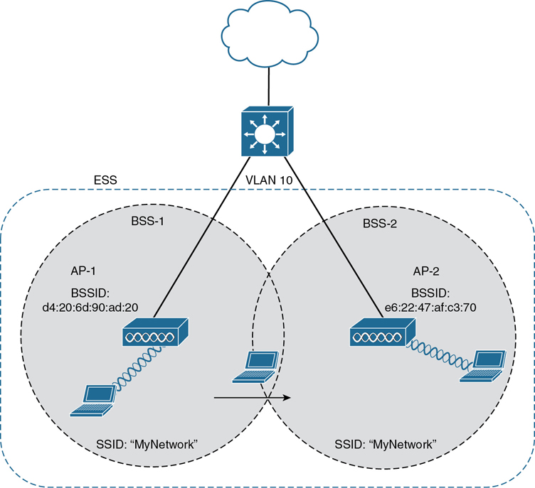
Figure 26-8 Scaling Wireless Coverage with an 802.11 Extended Service Set
In an ESS, a wireless client can associate with one AP while it is physically located near that AP. If the client later moves to a different location, it can associate with a different nearby AP automatically. Passing from one AP to another is called roaming. Keep in mind that each AP offers its own BSS on its own channel, to prevent interference between the APs. As a client device roams from one AP to another, it must scan the available channels to find a new AP (and BSS) to roam toward. In effect, the client is roaming from BSS to BSS, and from channel to channel.
Independent Basic Service Set
Usually a wireless network leverages APs for organization, control, and scalability. Sometimes that is not possible or convenient in an impromptu situation. For example, two people who want to exchange electronic documents at a meeting might not be able to find a BSS available or might want to avoid having to authenticate to a production network. In addition, many personal printers have the capability to print documents wirelessly, without relying on a regular BSS or AP.
The 802.11 standard allows two or more wireless clients to communicate directly with each other, with no other means of network connectivity. This is known as an ad hoc wireless network, or an independent basic service set (IBSS), as shown in Figure 26-9. For this to work, one of the devices must take the lead and begin advertising a network name and the necessary radio parameters, much like an AP would do. Any other device can then join as needed. IBSSs are meant to be organized in an impromptu, distributed fashion; therefore, they do not scale well beyond eight to ten devices.
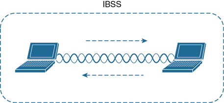
Figure 26-9 802.11 Independent Basic Service Set
Other Wireless Topologies
Wireless APs can be configured to operate in noninfrastructure modes when a normal BSS cannot provide the functionality that is needed. The following sections cover the most common modes.
Repeater
Normally, each AP in a wireless network has a wired connection back to the DS or switched infrastructure. To extend wireless coverage beyond a normal AP’s cell footprint, additional APs and their wired connections can be added. In some scenarios, it is not possible to run a wired connection to a new AP because the cable distance is too great to support Ethernet communication.
In that case, you can add an additional AP that is configured for repeater mode. A wireless repeater takes the signal it receives and repeats or retransmits it in a new cell area around the repeater. The idea is to move the repeater out away from the AP so that it is still within range of both the AP and the distant client, as shown in Figure 26-10.
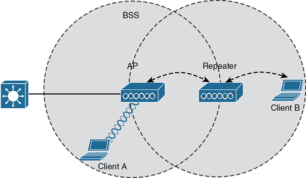
Figure 26-10 Extending the Range of an AP with a Wireless Repeater
If the repeater has a single transmitter and receiver, it must operate on the same channel that the AP is using. That can create the possibility that the AP’s signal will be received and retransmitted by the repeater, only to be received again by the AP—halving the effective throughput because the channel will be kept busy twice as long as before. As a remedy, some repeaters can use two transmitters and receivers to keep the original and repeated signals isolated on different channels. One transmitter and receiver pair is dedicated to signals in the AP’s cell, while the other pair is dedicated to signals in the repeater’s own cell.
Workgroup Bridge
Suppose you have a device that supports a wired Ethernet link but is not capable of having a wireless connection. For example, some mobile medical devices might be designed with only a wired connection. While it is possible to plug the device into an Ethernet connection when needed, a wireless connection would be much more practical. You can use a workgroup bridge (WGB) to connect the device’s wired network adapter to a wireless network.
Rather than providing a BSS for wireless service, a WGB becomes a wireless client of a BSS. In effect, the WGB acts as an external wireless network adapter for a device that has none. In Figure 26-11, an AP provides a BSS; Client A is a regular wireless client, while Client B is associated with the AP through a WGB.
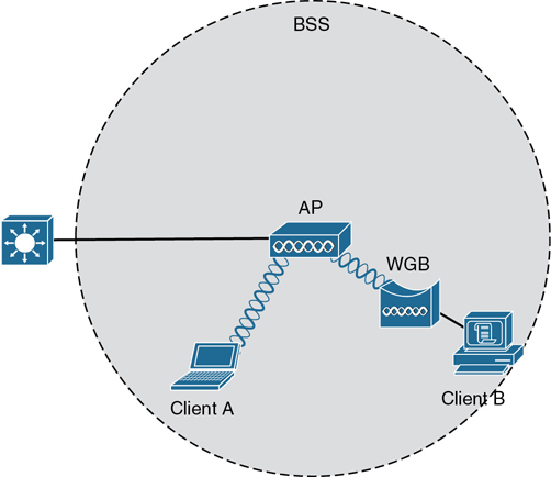
Figure 26-11 Nonwireless Device Connecting Through a Workgroup Bridge
You might encounter two types of workgroup bridges:
Universal workgroup bridge (uWGB): A single wired device can be bridged to a wireless network.
Workgroup bridge (WGB): A Cisco-proprietary implementation that allows multiple wired devices to be bridged to a wireless network.
Outdoor Bridge
An AP can be configured to act as a bridge to form a single wireless link from one LAN to another over a long distance. Outdoor bridged links are commonly used for connectivity between buildings or between cities.
If the LANs at two locations need to be bridged, a point-to-point bridged link can be used. One AP configured in bridge mode is needed on each end of the wireless link. Special purpose antennas are normally used with the bridges to focus their signals in one direction—toward the antenna of the AP at the far end of the link. This maximizes the link distance, as shown in Figure 26-12.
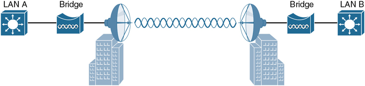
Figure 26-12 Point-to-Point Outdoor Bridge
Sometimes the LANs at multiple sites need to be bridged together. A point-to-multipoint bridged link allows a central site to be bridged to several other sites. The central site bridge is connected to an omnidirectional antenna, such that its signal is transmitted equally in all directions so that it can reach the other sites simultaneously. The bridges at each of the other sites can be connected to a directional antenna aimed at the central site. Figure 26-13 shows the point-to-multipoint scenario.

Figure 26-13 Point-to-Multipoint Outdoor Bridge
Mesh Network
To provide wireless coverage over a very large area, it is not always practical to run Ethernet cabling to every AP that would be needed. Instead, you could use multiple APs configured in mesh mode. In a mesh topology, wireless traffic is bridged from AP to AP, in a daisy-chain fashion, using another wireless channel.
Mesh APs can leverage dual radios—one using a channel in one range of frequencies and one a different range. Each mesh AP usually maintains a BSS on one channel, with which wireless clients can associate. Client traffic is then usually bridged from AP to AP over other channels as a backhaul network. At the edge of the mesh network, the backhaul traffic is bridged to the wired LAN infrastructure. Figure 26-14 shows a typical mesh network. With Cisco APs, you can build a mesh network indoors or outdoors. The mesh network runs its own dynamic routing protocol to work out the best path for backhaul traffic to take across the mesh APs.
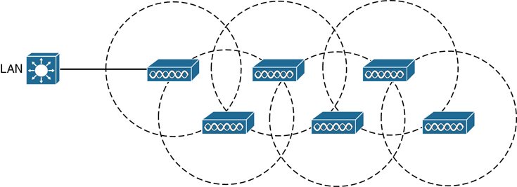
Figure 26-14 Typical Wireless Mesh Network
RF Overview
To send data across a wired link, an electrical signal is applied at one end and carried to the other end. The wire itself is continuous and conductive, so the signal can propagate rather easily. A wireless link has no physical strands of anything to carry the signal along.
How, then, can an electrical signal be sent across the air, or free space? Consider a simple analogy of two people standing far apart. One person wants to signal something to the other. They are connected by a long and somewhat loose rope; the rope represents free space. The sender at one end decides to lift his end of the rope high and hold it there so that the other end of the rope will also rise and notify the partner. After all, if the rope were a wire, he knows that he could apply a steady voltage at one end of the wire and it would appear at the other end. Figure 26-15 shows the end result; the rope falls back down after a tiny distance, and the receiver never notices a change.

Figure 26-15 Failed Attempt to Pass a Message Down a Rope
The sender tries a different strategy. He cannot push the rope, but when he begins to wave it up and down in a steady, regular motion, a curious thing happens. A continuous wave pattern appears along the entire length of the rope, as shown in Figure 26-16. In fact, the waves (each representing one up and down cycle of the sender’s arm) actually travel from the sender to the receiver.

Figure 26-16 Sending a Continuous Wave Down a Rope
In free space, a similar principle occurs. The sender (a transmitter) can send an alternating current into a section of wire (an antenna), which sets up moving electric and magnetic fields that propagate out and away as traveling waves. The electric and magnetic fields travel along together and are always at right angles to each other, as shown in Figure 26-17. The signal must keep changing, or alternating, by cycling up and down, to keep the electric and magnetic fields cycling and pushing ever outward.
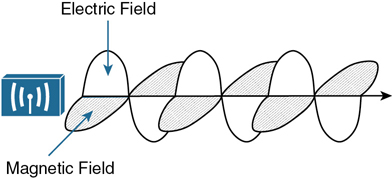
Figure 26-17 Traveling Electric and Magnetic Waves
Electromagnetic waves do not travel in a straight line. Instead, they travel by expanding in all directions away from the antenna. To get a visual image, think of dropping a pebble into a pond when the surface is still. Where it drops in, the pebble sets the water’s surface into a cyclic motion. The waves that result begin small and expand outward, only to be replaced by new waves. In free space, the electromagnetic waves expand outward in all three dimensions.
Figure 26-18 shows a simple idealistic antenna that is a single point at the end of a wire. The waves produced expand outward in a spherical shape. The waves will eventually reach the receiver, in addition to many other locations in other directions.
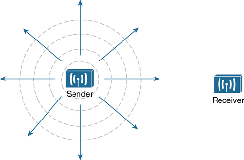
Figure 26-18 Wave Propagation with an Idealistic Antenna
At the receiving end of a wireless link, the process is reversed. As the electromagnetic waves reach the receiver’s antenna, they induce an electrical signal. If everything works right, the received signal will be a reasonable copy of the original transmitted signal.
The electromagnetic waves involved in a wireless link can be measured and described in several ways. One fundamental property is the frequency of the wave, or the number of times the signal makes one complete up and down cycle in 1 second. Figure 26-19 shows how a cycle of a wave can be identified. A cycle can begin as the signal rises from the center line, falls through the center line, and rises again to meet the center line. A cycle can also be measured from the center of one peak to the center of the next peak. No matter where you start measuring a cycle, the signal must make a complete sequence back to its starting position where it is ready to repeat the same cyclic pattern.
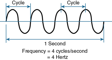
Figure 26-19 Cycles Within a Wave
In Figure 26-19, suppose that 1 second has elapsed, as shown. During that 1 second, the signal progressed through four complete cycles. Therefore, its frequency is 4 cycles/second or 4 hertz. A hertz (Hz) is the most commonly used frequency unit and is nothing other than one cycle per second.
Frequency can vary over a very wide range. As frequency increases by orders of magnitude, the numbers can become quite large. To keep things simple, the frequency unit name can be modified to denote an increasing number of zeros, as listed in Table 26-2.
Table 26-2 Frequency Unit Names
Unit |
Abbreviation |
Meaning |
|---|---|---|
Hertz |
Hz |
Cycles per second |
Kilohertz |
kHz |
1000 Hz |
Megahertz |
MHz |
1,000,000 Hz |
Gigahertz |
GHz |
1,000,000,000 Hz |
Figure 26-20 shows a simple representation of the continuous frequency spectrum ranging from 0 Hz to 1022 (or 1 followed by 22 zeros) Hz. At the low end of the spectrum are frequencies that are too low to be heard by the human ear, followed by audible sounds. The highest range of frequencies contains light, followed by X, gamma, and cosmic rays.
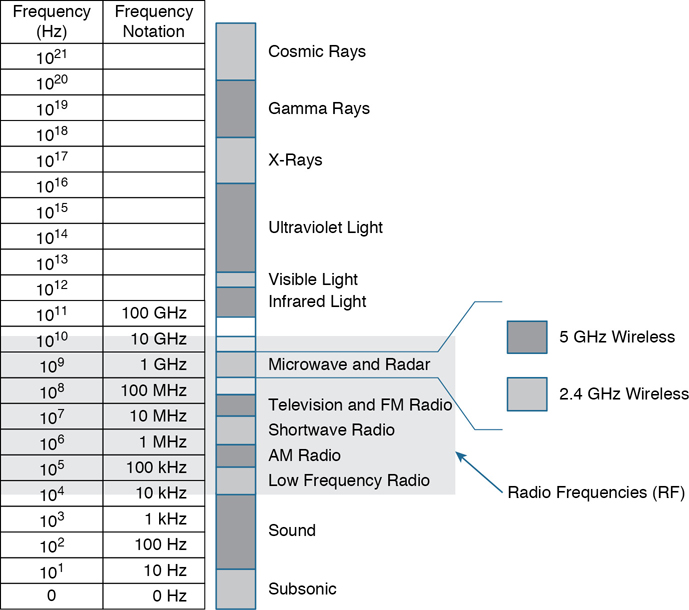
Figure 26-20 Continuous Frequency Spectrum
The frequency range from around 3 kHz to 300 GHz is commonly called radio frequency (RF). It includes many different types of radio communication, including low-frequency radio, AM radio, shortwave radio, television, FM radio, microwave, and radar. The microwave category also contains the two main frequency ranges that are used for wireless LAN communication: 2.4 and 5 GHz.
Wireless Bands and Channels
Because a range of frequencies might be used for the same purpose, it is customary to refer to the range as a band of frequencies. For example, the range from 530 kHz to around 1710 kHz is used by AM radio stations; therefore, it is commonly called the AM band or the AM broadcast band.
One of the two main frequency ranges used for wireless LAN communication lies between 2.400 and 2.4835 GHz. This is usually called the 2.4-GHz band, even though it does not encompass the entire range between 2.4 and 2.5 GHz. It is much more convenient to refer to the band name instead of the specific range of frequencies included.
The other wireless LAN range is usually called the 5-GHz band because it lies between 5.150 and 5.825 GHz. The 5-GHz band actually contains the following four separate and distinct bands:
5.150 to 5.250 GHz
5.250 to 5.350 GHz
5.470 to 5.725 GHz
5.725 to 5.825 GHz
Tip
You might have noticed that most of the 5-GHz bands are contiguous except for a gap between 5.350 and 5.470. At the time of this writing, this gap exists and cannot be used for wireless LANs. However, some governmental agencies have moved to reclaim the frequencies and repurpose them for wireless LANs. Efforts are also underway to add 5.825 through 5.925 GHz.
It is interesting that the 5-GHz band can contain several smaller bands. Remember that the term band is simply a relative term that is used for convenience. Do not worry about memorizing the band names or exact frequency ranges; just be aware of the two main bands at 2.4 and 5 GHz.
A frequency band contains a continuous range of frequencies. If two devices require a single frequency for a wireless link between them, which frequency can they use? Beyond that, how many unique frequencies can be used within a band? To keep everything orderly and compatible, bands are usually divided into a number of distinct channels. Each channel is known by a channel number and is assigned to a specific frequency. As long as the channels are defined by a national or international standards body, they can be used consistently in all locations. Figures 26-21 and 26-22 show the channel layout for the 2.4 and 5 GHz bands, respectively.

Figure 26-21 Channel Layout in the 2.4-GHz Band

Figure 26-22 Channel Layout in the 5-GHz Band
You might assume that an AP can use any channel number without affecting any APs that use other channel numbers. In the 5-GHz band, this is the case because each channel is allocated a frequency range that does not encroach on or overlap the frequencies allocated for any other channel. In other words, the 5-GHz band consists of nonoverlapping channels.

The same is not true of the 2.4-GHz band. Each of its channels is much too wide to avoid overlapping the next lower or upper channel number. In fact, each channel covers the frequency range that is allocated to more than four consecutive channels! Notice the width of the channel spacing in Figure 26-21 as compared to the width of one of the shaded signals centered on channels 1, 6, and 11. The only way to avoid any overlap between adjacent channels is to configure APs to use only channels 1, 6, and 11. Even though there are 14 channels available to use, you should always strive for nonoverlapping channels in your network.
APs and Wireless Standards
It might be obvious that wireless devices and APs should all be capable of operating on the same band. For example, a 5-GHz wireless phone can communicate only with an AP that offers Wi-Fi service on 5-GHz channels. In addition, the devices and APs must also share a compatibility with the parts of the 802.11 standard they support.
As the IEEE 802.11 Wi-Fi standard evolves and develops, new amendments with new functionality get proposed. These amendments are known by “802.11” followed by a one- or two-letter suffix until they are accepted and rolled up into the next generation of the complete 802.11 standard. Even then, it is common to see the amendment suffixes still used to distinguish specific functions.
You should be aware of several amendments that define important characteristics such as data rates, methods used to transmit and receive data, and so on. For the CCNA 200-301 exam, you should know which band each of the amendments listed in Table 26-3 uses. The ENCOR 300-401 exam goes further into the data rates and modulation and coding schemes used by each.
Table 26-3 Basic Characteristics of Some IEEE 802.11 Amendments
Amendment |
2.4 GHz |
5 GHz |
Max Data Rate |
Notes |
|---|---|---|---|---|
802.11-1997 |
Yes |
No |
2 Mbps |
The original 802.11 standard ratified in 1997 |
802.11b |
Yes |
No |
11 Mbps |
Introduced in 1999 |
802.11g |
Yes |
No |
54 Mbps |
Introduced in 2003 |
802.11a |
No |
Yes |
54 Mbps |
Introduced in 1999 |
802.11n |
Yes |
Yes |
600 Mbps |
HT (high throughput), introduced in 2009 |
802.11ac |
No |
Yes |
6.93 Gbps |
VHT (very high throughput), introduced in 2013 |
802.11ax |
Yes |
Yes |
4x 802.11ac |
High Efficiency Wireless, Wi-Fi6; expected late 2019; will operate on other bands too, as they become available |
The 802.11 amendments are not mutually exclusive. Wireless client devices and APs can be compatible with one or more amendments; however, a client and an AP can communicate only if they both support and agree to use the same amendment. When you look at the specifications for a wireless device, you may find supported amendments listed in a single string, separated by slashes. For example, a device that supports 802.11b/g will support both 802.11b and 802.11g. One that supports b/g/a/n/ac will support 802.11b, 802.11g, 802.11n, and 802.11ac. You should become familiar with Table 26-3 so that you can know which bands a device can use based on its 802.11 amendment support.
If a device can operate on both bands, how does it decide which band to use? APs can usually operate on both bands simultaneously to support any clients that might be present on each band. However, wireless clients typically associate with an AP on one band at a time, while scanning for potential APs on both bands. The band used to connect to an AP is chosen according to the operating system, wireless adapter driver, and other internal configuration. A wireless client can initiate an association with an AP on one band and then switch to the other band if the signal conditions are better there.
Note
Cisco APs have dual radios (sets of transmitters and receivers) to support BSSs on one 2.4-GHz channel and other BSSs on one 5-GHz channel simultaneously. Some models also have two 5-GHz radios that can be configured to operate BSSs on two different channels at the same time, providing wireless coverage to higher densities of users that are located in the same vicinity.
You can configure a Cisco AP to operate on a specific channel number. As the number of APs grows, manual channel assignment can become a difficult task. Fortunately, Cisco wireless architectures can automatically and dynamically assign each AP to an appropriate channel. The architecture is covered in Chapter 27, “Analyzing Cisco Wireless Architectures,” while dynamic channel assignment is covered on the ENCOR 300-401 exam.
In open space, RF signals propagate or reach further on the 2.4-GHz band than on the 5-GHz band. They also tend to penetrate indoor walls and objects easier at 2.4 GHz than 5 GHz. However, the 2.4-GHz band is commonly more crowded with wireless devices. Remember that only three nonoverlapping channels are available, so the chances of other neighboring APs using the same channels is greater. In contrast, the 5-GHz band has many more channels available to use, making channels less crowded and experiencing less interference.
Chapter Review
Review this chapter’s material using either the tools in the book or the interactive tools for the same material found on the book’s companion website. Table 26-4 outlines the key review elements and where you can find them. To better track your study progress, record when you completed these activities in the second column.
Table 26-4 Chapter Review Tracking
Review Element |
Review Date(s) |
Resource Used |
|---|---|---|
Review key topics |
|
Book, website |
Review key terms |
|
Book, website |
Answer DIKTA questions |
|
Book, PTP |
Review memory tables |
|
Website |
Review All the Key Topics
Table 26-5 Key Topics for Chapter 26
Key Topic Element |
Description |
Page Number |
|---|---|---|
Basic service set |
615 |
|
Multiple SSIDs |
618 |
|
Extended service set |
619 |
|
Paragraph |
Nonoverlapping channels and bands |
628 |
Basic Characteristics of Some 802.11 Amendments |
628 |
Key Terms You Should Know
Basic Service Set Identifier (BSSID)