Chapter 13. LAN Architecture
This chapter covers the following exam topics:
1.0 Network Fundamentals
1.2 Describe characteristics of network topology architectures
1.2.a 2 tier
1.2.b 3 tier
1.2.e Small office/home office (SOHO)
1.3 Compare physical interface and cabling types
1.3.c Concepts of PoE
By now you have learned a lot about Ethernet and Ethernet switches. You have learned how individual links work, with cabling and duplex settings as well as framing. You know how addresses work and how switches forward frames based on those addresses. You have seen how switches deal with redundancy, using STP/RSTP and collecting links into EtherChannels. And here in Volume 2, you have learned about a variety of security features available for switches, including Dynamic ARP Inspection, DHCP Snooping, and ARP Inspection.
What the earlier discussions of individual features do not do to any great extent is discuss architecture and design. You now know how switches work, but why would you connect switches in one topology versus another? If you could connect switches in two different topologies, why would you prefer one over the other? This chapter examines a few such design questions, specifically the topic areas mentioned in the CCNA 200-301 exam topics. (Note that the CCNA 200-301 exam does not include a comprehensive look at LAN design issues, but one of the current CCNP Enterprise exams does.)
This chapter covers three specific topics that have design-related considerations. The first section looks at the topology of a wired Ethernet LAN and the design terms two tier and three tier, which describe how many switch layers exist between the endpoints and the devices that lead out of the campus to some other site. Following that, the second section examines small office/home office (SOHO) LANs and how they differ from enterprise LANs. The final section introduces the concepts behind Power over Ethernet (PoE), along with the reasons why LAN design activities need to consider PoE.
“Do I Know This Already?” Quiz
Take the quiz (either here or use the PTP software) if you want to use the score to help you decide how much time to spend on this chapter. The letter answers are listed at the bottom of the page following the quiz. Appendix C, found both at the end of the book as well as on the companion website, includes both the answers and explanations. You can also find both answers and explanations in the PTP testing software.
Table 13-1 “Do I Know This Already?” Foundation Topics Section-to-Question Mapping
Foundation Topics Section |
Questions |
Analyzing Campus LAN Topologies |
1–3 |
Small Office/Home Office |
4 |
Power over Ethernet |
5–6 |
1. In a two-tier campus LAN design, which of the following are typically true of the topology design? (Choose two answers.)
The design uses a full mesh of links between access and distribution switches.
The design uses a partial mesh of links between access and distribution switches.
The design uses a partial mesh of links between the distribution and core switches.
The end-user and server devices connect directly to access layer switches.
2. In a three-tier campus LAN design, which of the following are typically true of the topology design? (Choose two answers.)
The design uses a partial mesh of links between access and distribution switches.
The design uses a full mesh of links between access and distribution switches.
The design uses a partial mesh of links between the distribution and core switches.
The end-user and server devices connect directly to distribution layer switches.
3. Which one answer gives the strongest match between one part of a typical three-tier design with the idea behind the listed generic topology design term?
The access layer looks like a partial mesh.
The distribution layer looks like a full mesh.
The distribution layer looks like a hybrid design.
The access layer looks like a star design.
4. Which answers list criteria typical of a SOHO network? (Choose two answers.)
The AP functions using standalone mode.
The AP functions using a split-MAC architecture using a WLC.
A single networking device implements the router, switch, AP, and firewall functions.
A separate networking device implements each function (router, switch, AP, and firewall).
5. Which answer describes how a LAN switch dynamically chooses the initial power level to apply to a UTP cable with PoE?
Autonegotiation
CDP
LLDP
Preconfigured values
6. Which of the following refer to standards that deliver power over all four pairs in a UTP cable? (Choose two answers.)
PoE
UPoE
PoE+
UPoE+
Answers to the “Do I Know This Already?” quiz:
1 B, D
2 A, C
3 D
4 A, C
5 A
6 B, D
Foundation Topics
Analyzing Campus LAN Topologies
The term campus LAN refers to the LAN created to support the devices in a building or in multiple buildings in somewhat close proximity to one another. For example, a company might lease office space in several buildings in the same office park. The network engineers can then build a campus LAN that includes switches in each building, plus Ethernet links between the switches in the buildings, to create a larger campus LAN.
When planning and designing a campus LAN, the engineers must consider the types of Ethernet available and the cabling lengths supported by each type. The engineers also need to choose the speeds required for each Ethernet segment. In addition, some thought needs to be given to the idea that some switches should be used to connect directly to end-user devices, whereas other switches might need to simply connect to a large number of these end-user switches. Finally, most projects require that the engineer consider the type of equipment that is already installed and whether an increase in speed on some segments is worth the cost of buying new equipment.
This first of three major sections of the chapter discusses the topology of a campus LAN design. Network designers do not just plug in devices to any port and connect switches to each other in an arbitrary way, like you might do with a few devices on the same table in a lab. Instead, there are known better ways to design the topology of a campus LAN, and this section introduces some of the key points and terms
Two-Tier Campus Design (Collapsed Core)
To sift through all the requirements for a campus LAN, and then have a reasonable conversation about it with peers, most Cisco-oriented LAN designs use some common terminology to refer to the design. For this book’s purposes, you should be aware of some of the key campus LAN design terminology.
The Two-Tier Campus Design
Figure 13-1 shows a typical design of a large campus LAN, with the terminology included in the figure. This LAN has around 1000 PCs connected to switches that support around 25 ports each. Explanations of the terminology follow the figure.
Cisco uses three terms to describe the role of each switch in a campus design: access, distribution, and core. The roles differ based on whether the switch forwards traffic from user devices and the rest of the LAN (access), or whether the switch forwards traffic between other LAN switches (distribution and core).

Figure 13-1 Campus LAN with Design Terminology Listed
Access switches connect directly to end users, providing user device access to the LAN. Access switches normally send traffic to and from the end-user devices to which they are connected and sit at the edge of the LAN.
Distribution switches provide a path through which the access switches can forward traffic to each other. By design, each of the access switches connects to at least one distribution switch, typically to two distribution switches for redundancy. The distribution switches provide the service of forwarding traffic to other parts of the LAN. Note that most designs use at least two uplinks to two different distribution switches (as shown in Figure 13-1) for redundancy.
The figure shows a two-tier design, with the tiers being the access tier (or layer) and the distribution tier (or layer). A two-tier design solves two major design needs:
Provides a place to connect end-user devices (the access layer, with access switches)
Connects the switches with a reasonable number of cables and switch ports by connecting all 40 access switches to two distribution switches
Topology Terminology Seen Within a Two-Tier Design
The networking world uses several common terms about LAN and WAN topology and design including these:
Star: A design in which one central device connects to several others, so that if you drew the links out in all directions, the design would look like a star with light shining in all directions.
Full mesh: For any set of network nodes, a design that connects a link between each pair of nodes.
Partial mesh: For any set of network nodes, a design that connects a link between some pairs of nodes, but not all. In other words, a mesh that is not a full mesh.
Hybrid: A design that combines topology design concepts into a larger (typically more complex) design.
Armed with those formal definitions, note that the two-tier design is indeed a hybrid design that uses both a star topology at the access layer and a partial mesh at the distribution layer. To see why, consider Figure 13-2. It redraws a typical access layer switch, but instead of putting the PCs all below the switch, it spreads them around the switch. Then on the right, a similar version of the same drawing shows why the term star might be used—the topology looks a little like a child’s drawing of a star.

Figure 13-2 The Star Topology Design Concept in Networking
The distribution layer creates a partial mesh. If you view the access and distribution switches as nodes in a design, some nodes have a link between them, and some do not. Just refer to Figure 13-1 and note that, by design, none of the access layer switches connect to each other.
Finally, a design could use a full mesh. However, for a variety of reasons beyond the scope of the design discussion here, a campus design typically does not need to use the number of links and ports required by a full mesh design. However, just to make the point, first consider how many links and switch ports would be required for a single link between nodes in a full mesh, with six nodes, as shown in Figure 13-3.

Figure 13-3 Using a Full Mesh at the Distribution Layer, 6 Switches, 15 Links
Even with only six switches, a full mesh would consume 15 links (and 30 switch ports—two per link).
Now think about a full mesh at the distribution layer for a design like Figure 13-1, with 40 access switches and two distribution switches. Rather than drawing it and counting it, the number of links is calculated with this old math formula from high school: N(N – 1) / 2, or in this case, 42 * 41 / 2 = 861 links, and 1722 switch ports consumed among all switches.
For comparison’s sake, the partial mesh design of Figure 13-1, with a pair of links from each access switch to each distribution switch, requires only 160 links and a total of 320 ports among all switches.
Three-Tier Campus Design (Core)
The two-tier design of Figure 13-1, with a partial mesh of links at the distribution layer, happens to be the most common campus LAN design. It also goes by two common names: a two-tier design (for obvious reasons) and a collapsed core (for less obvious reasons). The term collapsed core refers to the fact that the two-tier design does not have a third tier, the core tier. This next topic examines a three-tier design that does have a core, for perspective.
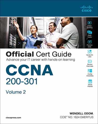
Imagine your campus has just two or three buildings. Each building has a two-tier design inside the building, with a pair of distribution switches in each building and access switches spread around the building as needed. How would you connect the LANs in each building? Well, with just a few buildings, it makes sense to simply cable the distribution switches together, as shown in Figure 13-4.
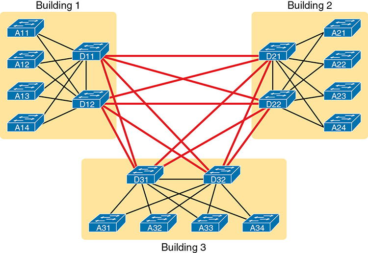
Figure 13-4 Two-Tier Building Design, No Core, Three Buildings
The design in Figure 13-4 works well, and many companies use this design. Sometimes the center of the network uses a full mesh, sometimes a partial mesh, depending on the availability of cables between the buildings.
However, a design with a third tier (a core tier) saves on switch ports and on cables in larger designs. And note that with the links between buildings, the cables run outside, are often more expensive to install, and are almost always fiber cabling with more expensive switch ports, so conserving the number of cables used between buildings can help reduce costs.
A three-tier core design, unsurprisingly at this point, adds a few more switches (core switches), which provide one function: to connect the distribution switches. Figure 13-5 shows the migration of the Figure 13-4 collapsed core (that is, a design without a core) to a three-tier core design.
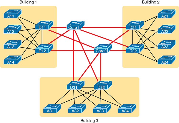
Figure 13-5 Three-Tier Building Design (Core Design), Three Buildings
By using a core design, with a partial mesh of links in the core, you still provide connectivity to all parts of the LAN and to the routers that send packets over the WAN, just with fewer links between buildings.
The following list summarizes the terms that describe the roles of campus switches:
Access: Provides a connection point (access) for end-user devices. Does not forward frames between two other access switches under normal circumstances.
Distribution: Provides an aggregation point for access switches, providing connectivity to the rest of the devices in the LAN, forwarding frames between switches, but not connecting directly to end-user devices.
Core: Aggregates distribution switches in very large campus LANs, providing very high forwarding rates for the larger volume of traffic due to the size of the network.
Topology Design Terminology
To close the discussion of Enterprise LAN topology, the next topic applies some of the generic topology terms to a typical two-tier design.
Consider Figure 13-6, which shows a few of the terms. First, on the left, drawings often show access switches with a series of cables, parallel to each other. However, the combinations of an access switch and its access links is often called a star topology. Why? Look at the redrawn access switch in the center of the figure, with the cables radiating out from the center. It does not look like a real star, but it looks a little like a child’s drawing of a star, hence the term star topology.
Figure 13-6 LAN Design Terminology
The right side of the figure repeats a typical two-tier design, focusing on the mesh of links between the access and distribution switches. Any group of nodes that connect with more links than a star topology is typically called a mesh. In this case, the mesh is a partial mesh, because not all nodes have a direct link between each other. A design that connects all nodes with a link would be a full mesh.
Real networks make use of these topology ideas, but often a network combines the ideas together. For instance, the right side of Figure 13-6 combines the star topology of the access layer with the partial mesh of the distribution layer. So you might hear these designs that combine concepts called a hybrid design.
Small Office/Home Office
Now that you know more about design choices and terms for an enterprise LAN, this next section examines one particular type of smaller LAN: the small office/home office (SOHO) LAN. SOHO refers to designs and implementations that have such a small volume of requirements—few switch ports, few APs, few routers and WAN links—that the design differs significantly. The term itself refers to the two most common cases: a user who works from home or a small office with a small number of workers and devices. This next short topic points out a few of the highlights that make a SOHO network different from an enterprise network.
First, as a reminder, the IEEE defines both Ethernet LANs and wireless LANs (WLANs). In case it was not obvious yet, all Ethernet standards use cables—that is, Ethernet defines wired LANs. The IEEE 802.11 working group defines wireless LANs, also called Wi-Fi per a trademarked term from the Wi-Fi Alliance (www.wi-fi.org), a consortium that helps encourage wireless LAN development in the marketplace.
Most of you have used Wi-Fi, and may use it daily. Some of you may have set it up at home, with a basic setup as shown in Figure 13-7. In a home, you probably used a single consumer device called a wireless router. One side of the device connects to the Internet, while the other side connects to the devices in the home. In the home, the devices can connect either with Wi-Fi or with a wired Ethernet cable.
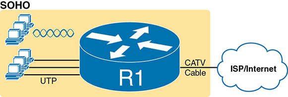
Figure 13-7 A Typical Home Wired and Wireless LAN
While the figure shows the hardware as a single router icon, internally, that one wireless router acts like separate devices you would find in an enterprise campus:
An Ethernet switch, for the wired Ethernet connections
A wireless access point (AP), to communicate with the wireless devices and forward the frames to/from the wired network
A router, to route IP packets to/from the LAN and WAN (Internet) interfaces
A firewall, which often defaults to allow only clients to connect to servers in the Internet, but not vice versa
Figure 13-8 repeats the previous figure, breaking out the internal components as if they were separate physical devices, just to make the point that a single consumer wireless router acts like several different devices.
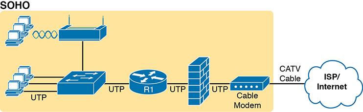
Figure 13-8 A Representation of the Functions Inside a Consumer Wireless Routing Product
In a SOHO wireless LAN, the wireless AP acts autonomously, rather than with a WLC, doing all the work required to create and control the WLAN. In other words, the autonomous AP communicates with the various wireless devices using 802.11 protocols and radio waves. It uses Ethernet protocols on the wired side. It converts between the differences in header formats between 802.11 and 802.3 frames before forwarding to/from 802.3 Ethernet and 802.11 wireless frames. But it does not encapsulate frames in CAPWAP, because the AP will not send the frames to a WLC.
For the Internet connection, the router (combo) device connects with any available Internet access technology, including cable Internet, DSL, 4G/5G wireless, or fiber Ethernet. Note that Chapter 14, “WAN Architecture,” introduces those technologies.
Power over Ethernet (PoE)
Just walk around any building and you see electrical power outlets everywhere. When finishing the interior of a building, electricians run electrical cables and install electrical outlets to any and every location that might need power. They also run power cables so that devices such as light fixtures can be wired to power as well. And when network engineers thought about electrical power, they thought in terms of making sure the electricians had run enough power to the wiring closets and other locations to power the networking devices.
Power over Ethernet (PoE) changes that thinking so that the responsibility to provide electrical power to some devices can fall to the network engineering team. Some classes of device types have been built to be able to receive their power over the Ethernet cable, rather than using a separate power cord. To make that work, the LAN switch connected to the cable must supply that power over the cable. By using PoE, companies can gain several advantages, including reduced cost by requiring fewer cable runs and better power management capabilities as compared with using a traditional electrical power cable run and power outlet. This final section of the chapter examines PoE.
PoE Basics
The family of standards that supply power goes by the general name Power over Ethernet (PoE). With PoE, some device, typically a LAN switch, acts as the Power Sourcing Equipment (PSE)—that is, the device that supplies DC power over the Ethernet UTP cable (as shown in Figure 13-9). A device that has the capability to be powered over the Ethernet cable, rather than by some other power connector on the device, is called the Powered Device (PD).
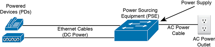
Figure 13-9 Power over Ethernet Terminology
PoE has a great advantage for devices installed to locations that often do not have a preinstalled power cable or power output. For instance, wireless design places APs in a wide range across the ceiling of a floor (or story) in a building. Also, IP video cameras might be placed in the ceiling corners inside or at various outside locations. Instead of running new power and new network cables to support each device, a single Ethernet cable run can supply power to the device while allowing normal Ethernet communications over the same cable and same wire pairs.
PoE also helps in some less obvious practical ways because it supplies DC power over the Ethernet cable, so the device does not need an AC/DC converter. For instance, devices like laptops and IP phones use a power cord that includes a power brick—an AC-to-DC converter—which converts the AC power from the power outlet to the DC power needed by the device. PoE supplies DC current over the Ethernet cable. So, for an IP Phone, for instance, no more power cable and no more power brick cluttering the desk or taking up a power outlet.
PoE Operation
PoE must have a means to avoid harming the devices on the end of the circuit. Every electrical device can be harmed by receiving too much current into the device, which is why electricians install circuit breakers and why we use surge protectors. Applying power over an Ethernet cable could have the same effect, harming the device on the other end, if the device does not support PoE. So PoE must (and does) have processes in place to determine if PoE is needed, and for how much power, before applying any potentially harmful power levels to the circuit.
PoE, standardized by the IEEE, extends the same IEEE autonegotiation mechanisms. In fact, the mechanisms need to work before the PD has booted, because the PD needs power before it can boot and initialize. By using these IEEE autonegotiation messages and watching for the return signal levels, PoE can determine whether the device on the end of the cable requires power (that is, it is a PD) and how much power to supply. This list details the major steps:
Step 1. Do not supply power on a PoE-capable port unless negotiation identifies that the device needs power.
Step 2. Use Ethernet autonegotiation techniques, sending low power signals and monitoring the return signal, to determine the PoE power class, which determines how much power to supply to the device.
Step 3. If the device is identified as a PD, supply the power per the power class, which allows the device to boot.
Step 4. Monitor for changes to the power class, both with autonegotiation and listening for CDP and LLDP messages from the PD.
Step 5. If a new power class is identified, adjust the power level per that class.
The negotiation processes result in the PDs signaling how many watts of power they would like to receive from the PSE. Depending on the specific PoE standard, the PSE will then supply the power, either over two pairs or four pairs, as noted in Table 13-2.
Table 13-2 Power over Ethernet Standards
Name |
Standard |
Watts at PSE |
Powered Wire Pairs |
Cisco Inline Power |
Cisco |
7 |
2 |
PoE |
802.3af |
15 |
2 |
PoE+ |
802.3at |
30 |
2 |
UPoE |
802.3bt |
60 |
4 |
UpoE+ |
802.3bt |
100 |
4 |
Cisco has been developing products to use some form of PoE since around 2000. Cisco has often developed prestandard power capabilities, like its original Cisco Inline Power (ILP) feature. Over time, the IEEE has produced standards similar to Cisco’s power features, with Cisco supporting the standard version once completed. However, for the most part, the Cisco literature refers to the more common names in the first column of the table.
PoE and LAN Design
Most of the LAN switch features discussed in this book (and in CCNA 200-301 Official Cert Guide, Volume 1) exist as software features. Once you learn about a software feature, in some cases all you have to do is configure the feature and start using it. (In some cases, you might need to research and license the feature first.) Regardless, adding the feature takes little or no prior planning.
PoE does require some planning and engineering effort when designing a LAN, both when planning for the cable plant (both Ethernet and electrical), as well as when planning for new networking hardware. Planning with PoE in mind prepares the network to supply power to network devices, rather than reacting and missing opportunities to save money and time.
The following list includes some of the key points to consider when planning a LAN design that includes PoE:
Powered Devices: Determine the types of devices and specific models, along with their power requirements.
Power Requirements: Plan the numbers of different types of PDs to connect into each wiring closet to build a power budget. That power budget can then be processed to determine the amount of PoE power to make available through each switch.
Switch Ports: Some switches support PoE standards on all ports, some on no ports, some on a subset of ports. Research the various switch models so that you purchase enough PoE-capable ports for the switches planned for each wiring closet.
Switch Power Supplies: Without PoE, when purchasing a switch, you choose a power supply so that it delivers enough power to power the switch itself. With PoE, the switch acts as a distributor of electrical power, so the switch power supply must deliver many more watts than it needs to run the switch itself. You will need to create a power budget per switch, based on the number of connected PDs, and purchase power supplies to match those requirements.
PoE Standards versus Actual: Consider the number of PoE switch ports needed, the standards they support, the standards supported by the PDs, and how much power they consume. For instance, a PD and a switch port may both support PoE+, which supports up to 30 watts supplied by the PSE. However, that powered device may need at most 9 watts to operate, so your power budget needs to reserve less power than the maximum for those devices.
Chapter Review
One key to doing well on the exams is to perform repetitive spaced review sessions. Review this chapter’s material using either the tools in the book or interactive tools for the same material found on the book’s companion website. Refer to the “Your Study Plan” element for more details. Table 13-3 outlines the key review elements and where you can find them. To better track your study progress, record when you completed these activities in the second column.
Table 13-3 Chapter Review Tracking
Review Element |
Review Date(s) |
Resource Used |
Review key topics |
|
Book, app |
Review key terms |
|
Book, app |
Answer DIKTA questions |
|
Book, PTP |
Review memory tables |
|
Book, app |
Review All the Key Topics
Table 13-4 Key Topics for Chapter 13
Key Topic Element |
Description |
Page Number |
Campus LAN design terms |
||
Star topology |
||
A two-tier (collapsed core) LAN topology |
||
A three-tier (core) LAN topology |
||
List |
Definitions for LAN core, distribution, and access layers |
|
List |
Components in an integrated SOHO network device |
|
PoE roles and terms |
||
List |
Typical steps to discover power requirements with PoE |