Chapter 14. WAN Architecture
This chapter covers the following exam topics:
1.0 Network Fundamentals
1.2 Describe the characteristics of network topology architecture
1.2.d WAN
5.0 Security Fundamentals
5.5 Describe remote access and site-to-site VPNs
The CCNA 200-301 exam topics include only brief mentions of WAN topics. Because of that sparse attention to WANs, the CCNA 200-301 Official Cert Guide, Volume 1, introduced just enough detail about two types of WAN links—point-to-point serial and point-to-point Ethernet WAN links—so that you could understand IP routing, which is a major focus in CCNA.
This chapter now turns our attention to WAN topics for a deeper look at three branches of WAN technology. As usual for this book’s discussion of WAN services, the service is viewed mostly from the perspective of the enterprise, as the customer of some WAN service provider (SP). That means the discussion focuses on what the enterprise receives from the service, rather than how the service provider implements the service inside its network. (Note that Cisco’s Service Provider certification track explores the details of how an SP implements its network.)
This chapter begins with a discussion of Metro Ethernet, a technology that defines how to use Ethernet links between a customer site and the SP. The second section then examines MPLS VPNs, even though MPLS VPNs came before Metro Ethernet historically. The chapter introduces Metro Ethernet first because the many similarities between using Ethernet in the LAN and using Ethernet in the WAN make this topic easier to learn.
The chapter closes with a third section about how to use the Internet as a private WAN service by using virtual private network (VPN) technology. The Internet does not inherently provide a private service in that any attacker who gets a copy of your packets as they pass through the Internet can read the contents. VPN servers secure the data sent over the Internet, effectively creating a private WAN service over the public Internet.
“Do I Know This Already?” Quiz
Take the quiz (either here or use the PTP software) if you want to use the score to help you decide how much time to spend on this chapter. The letter answers are listed at the bottom of the page following the quiz. Appendix C, found both at the end of the book as well as on the companion website, includes both the answers and explanations. You can also find both answers and explanations in the PTP testing software.
Table 14-1 “Do I Know This Already?” Foundation Topics Section-to-Question Mapping
Foundation Topics Section |
Questions |
Metro Ethernet |
1–3 |
Multiprotocol Label Switching (MPLS) |
4–6 |
Internet VPNs |
7 |
1. Which of the following topology terms most closely describe the topology created by a Metro Ethernet Tree (E-Tree) service? (Choose two answers.)
Full mesh
Partial mesh
Hub and spoke
Point-to-point
2. Which of the following is the most likely technology used for an access link to a Metro Ethernet service?
100BASE-LX10
High-speed TDM (for example, T3, E3)
MPLS
100BASE-T
3. An enterprise uses a Metro Ethernet WAN with an Ethernet LAN (E-LAN) service, with the company headquarters plus 10 remote sites connected to the service. The enterprise uses OSPF at all sites, with one router connected to the service from each site. Which of the following are true about the Layer 3 details most likely used with this service and design? (Choose two answers.)
The WAN uses one IP subnet.
The WAN uses 10 or more IP subnets.
A remote site router would have one OSPF neighbor.
A remote site router would have 10 OSPF neighbors.
4. An enterprise uses an MPLS Layer 3 VPN with the company headquarters connected plus 10 remote sites connected to the service. The enterprise uses OSPF at all sites, with one router connected to the service from each site. Which of the following are true about the Layer 3 details most likely used with this service and design? (Choose two answers.)
The WAN uses one IP subnet.
The WAN uses 10 or more IP subnets.
A remote site router would have one OSPF neighbor.
A remote site router would have 10 or more OSPF neighbors.
5. Which of the following answers is most accurate about access link options for an MPLS network?
Uses only TDM (T1, T3, E1, E3, etc.)
Uses only Ethernet
Uses only DSL and cable
Uses a wide variety of Layer 1 and Layer 2 networking technologies
6. An enterprise connects 20 sites into an MPLS VPN WAN. The enterprise uses OSPF for IPv4 routes at all sites. Consider the OSPF area design options and the PE-CE links. Which of the following answers is most accurate about OSPF areas and the PE-CE links?
The PE-CE link may or may not be chosen to be in backbone area 0.
The PE-CE link must not be in the backbone area 0.
The PE-CE link must be in the backbone area 0.
The PE-CE link will not be in any OSPF area.
7. A colleague mentions using a remote access VPN. Which of the following protocols or technologies would you expect your colleague to have used?
TLS
IPsec
GRE
FTPS
Answers to the “Do I Know This Already?” quiz:
1 B, C
2 A
3 A, D
4 B, C
5 D
6 A
7 A
Foundation Topics
Metro Ethernet
Metro Ethernet (MetroE) includes a variety of WAN services with some common features. Each MetroE service uses Ethernet physical links to connect the customer’s device to the service provider’s device. Second, the service is a Layer 2 service in that the WAN provider forwards Ethernet frames from one customer device to another.
To begin the conversation with a basic view, Metro Ethernet acts much as if the WAN service were created by one Ethernet switch, as shown in Figure 14-1. The figure shows four sites in the same company, each with a router. Each router is connected to the WAN service with an Ethernet link of some kind; those Ethernet links typically use one of the fiber Ethernet standards due to the distances involved. From the customer’s perspective (that is, from the perspective of the enterprise that is the customer of the WAN SP), the WAN service acts like a LAN switch in that it forwards Ethernet frames.

Figure 14-1 Metro Ethernet Concept as a Large Ethernet Switch
Although the main concept makes a Metro Ethernet service act like a big LAN switch, there are many options, and you should understand the basics of each. Additionally, many customers connect to a Metro Ethernet service with either routers or Layer 3 switches, which brings up some Layer 3 issues with IP addressing and routing protocols. This section closes with a discussion of the Layer 3 issues.
Metro Ethernet Physical Design and Topology
From an enterprise perspective, to use a Metro Ethernet service, each site needs to connect to the service with (at least) one Ethernet link. There is no need to connect each enterprise router to each other enterprise router directly with a physical link. For instance, in Figure 14-1 in the previous section, each of the four enterprise routers connects to the SP’s MetroE service with one physical Ethernet link, rather than connecting directly to the other enterprise routers.
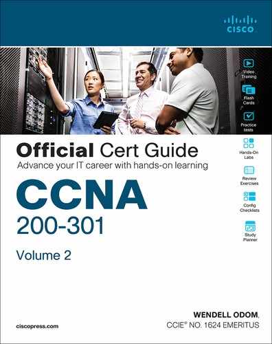
From the SP perspective, the SP needs to build a network to create the Metro Ethernet service. To keep costs lower the SP puts a device (typically an Ethernet switch) physically near to as many customer sites as possible, in an SP facility called a point of presence (PoP). Those SP switches need to be near enough to many customer locations so that some Ethernet standard supports the distance from the SP’s PoP to each customer site. Figure 14-2 collects some of these terms and ideas together.
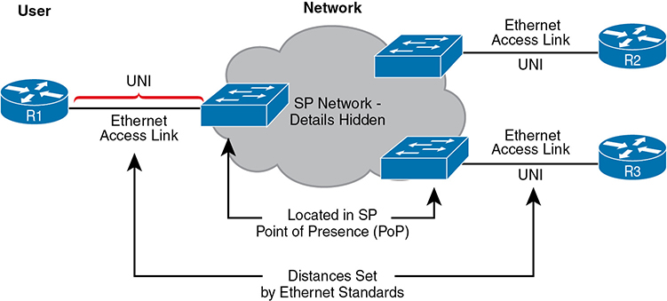
Figure 14-2 Ethernet Access Links into a Metro Ethernet Service
Working through the details in the figure, the physical link between the customer and the SP is called an access link or, when using Ethernet specifically, an Ethernet access link. Everything that happens on that link falls within the definition of the user network interface, or UNI. Breaking down the term UNI, the word network refers to the SP’s network, while the SP’s customer (the enterprise) is known as the user of the network.
Focusing on the center of Figure 14-2, the SP’s network remains hidden to a great extent. The SP promises to deliver Ethernet frames across the WAN. To do that, the access links connect to an Ethernet switch. As you can imagine, the switch will look at the Ethernet header’s MAC address fields and at 802.1Q trunking headers for VLAN tags, but the details inside the network remain hidden.
The UNI references a variety of standards, including the fact that any IEEE Ethernet standard can be used for the access link. Table 14-2 lists some of the standards you might expect to see used as Ethernet access links, given their support of longer distances than the standards that use UTP cabling.
Table 14-2 IEEE Ethernet Standards Useful for Metro Ethernet Access
Name |
Speed |
Distance |
100BASE-LX10 |
100 Mbps |
10 Km |
1000BASE-LX |
1 Gbps |
5 Km |
1000BASE-LX10 |
1 Gbps |
10 Km |
1000BASE-ZX |
1 Gbps |
100 Km |
10GBASE-LR |
10 Gbps |
10 Km |
10GBASE-ER |
10 Gbps |
40 Km |
Ethernet WAN Services and Topologies
Beyond adding a physical Ethernet connection from each site into the SP’s Metro Ethernet WAN service, the enterprise must choose between several possible variations of MetroE services. Those variations use different topologies that meet different customer needs.
MEF (www.mef.net) defines the standards for Metro Ethernet, including the specifications for different kinds of MetroE services. Table 14-3 lists three service types described in this chapter and their topologies. The next few pages after the table go into more depth about each.
Table 14-3 Three MEF Service Types and Their Topologies
MEF Service Name |
MEF Short Name |
Topology Terms |
Description |
Ethernet Line Service |
E-Line |
Point-to-point |
Two customer premise equipment (CPE) devices can exchange Ethernet frames, similar in concept to a leased line. |
Ethernet LAN Service |
E-LAN |
Full mesh |
This service acts like a LAN, in that all devices can send frames to all other devices. |
Ethernet Tree Service |
E-Tree |
Hub and spoke; partial mesh; point-to-multipoint |
A central site can communicate to a defined set of remote sites, but the remote sites cannot communicate directly. |
Ethernet Line Service (Point-to-Point)
The Ethernet Line Service, or E-Line, is the simplest of the Metro Ethernet services. The customer connects two sites with access links. Then the MetroE service allows the two customer devices to send Ethernet frames to each other. Figure 14-3 shows an example, with routers as the CPE devices.
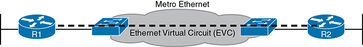
Figure 14-3 Point-to-Point Topology in Metro Ethernet E-Line Service Between Routers
As with all MetroE services, the promise made by the service is to deliver Ethernet frames across the service, as if the two customer routers had a rather long crossover cable connected between them. In fact, the E-Line service is the same Ethernet WAN service you have already seen in many examples throughout this book and CCNA 200-301 Official Cert Guide, Volume 1. For instance, in this case:
The routers would use physical Ethernet interfaces.
The routers would configure IP addresses in the same subnet as each other.
Their routing protocols would become neighbors and exchange routes.
The MetroE specifications define the concept of an Ethernet Virtual Connection, or EVC, to define which user (customer) devices can communicate with which. By definition, an E-Line service (as shown in Figure 14-4) creates a point-to-point EVC, meaning that the service allows two endpoints to communicate.
Figure 14-4 Using Multiple E-Lines, One for Each Remote Site
It may be that an enterprise wants to implement a network exactly as shown in Figure 14-3, with two sites and two routers, with MetroE WAN connectivity using an E-Line service. Other variations exist, even other variations using an E-Line.
For example, think of a common enterprise WAN topology with a central site and 100 remote sites. As shown so far, with an E-Line service, the central site router would need 100 physical Ethernet interfaces to connect to those 100 remote sites. That could be expensive. As an alternative, the enterprise could use the design partially shown in Figure 14-4 (just three remote sites shown). In this case:
The central site router uses a single 10-Gbps access link.
The central site connects to 100 E-Lines (only three shown).
All the E-Lines send and receive frames over the same access link.
Note that this chapter does not get into the configuration details for WAN services. However, designs like Figure 14-4, with multiple E-Line services on a single access link, use 802.1Q trunking, with a different VLAN ID for each E-Line service. As a result, the router configuration can use a typical router configuration with trunking and subinterfaces.
Before moving on to the next MetroE service, note that the customer could use switches instead of routers to connect to the WAN. Historically, enterprise engineers place routers at the edge of a WAN, in part because that device connected to both the WAN and the LAN, and the LAN and WAN used different types of physical interfaces and different data-link protocols. As a result of how routing works, routers served as the perfect device to sit at the edge between LAN and WAN (called the WAN edge). With MetroE, the LAN and WAN are both Ethernet, so an Ethernet switch becomes an option.
Ethernet LAN Service (Full Mesh)
Imagine an enterprise needs to connect several sites to a WAN, and the goal is to allow every site to send frames directly to every other site. You could do that with E-Lines, but you would need possibly lots of E-Lines. For instance, to connect three sites with E-Lines so that each site could send frames directly to each other, you only need three E-Lines. But with four, five, and six sites, you would need 6, 10, and 15 E-Lines, respectively. Get up to 20 sites for which all could send frames directly to each other, and you would need 190 E-Lines. (The formula is N(N – 1) / 2.)
The people who created MetroE anticipated the need for designs that allow a full mesh—that is, for each pair of nodes in the service to send frames to each other directly. In fact, allowing all devices to send directly to every other device sounds a lot like an Ethernet LAN, so the MetroE service is called an Ethernet LAN service, or E-LAN.
One E-LAN service allows all devices connected to that service to send Ethernet frames directly to every other device, just as if the Ethernet WAN service were one big Ethernet switch. Figure 14-5 shows a representation of a single E-LAN EVC. In this case, the one EVC connects to four customer sites, creating one E-LAN. Routers R1, R2, R3, and R4 can all send frames directly to each other. They would also all be in the same Layer 3 subnet on the WAN.
An E-LAN service connects the sites in a full mesh. The term full mesh refers to a design that, for a set of devices, creates a direct communication path for each pair. In contrast, a partial mesh refers to a design in which only some of the pairs can communicate directly. The Ethernet Tree service (E-Tree), as discussed in the next topic, creates a partial mesh design.

Figure 14-5 MetroE Ethernet LAN Service—Any-to-Any Forwarding over the Service
Ethernet Tree Service (Hub and Spoke)
The Ethernet Tree service (E-Tree) creates a WAN topology in which the central site device can send Ethernet frames directly to each remote (leaf) site, but the remote (leaf) sites can send only to the central site. Figure 14-6 shows the topology, again with a single EVC. In this case, router R1 is the root site, and can send to all three remote sites. Routers R2, R3, and R4 can send only to R1.
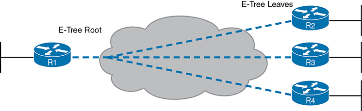
Figure 14-6 E-Tree Service Creates a Hub-and-Spoke Topology
With an E-Tree, the central site serves as the root of a tree and each remote site as one of the leaves. The topology goes by many names: partial mesh, hub and spoke, and point-to-multipoint. Regardless of the term you use, an E-Tree service creates a service that works well for designs with a central site plus many remote sites.
Layer 3 Design Using Metro Ethernet
Now that you know the basics of the E-Line (point-to-point), E-LAN (full mesh), and E-Tree (point-to-multipoint, hub and spoke) services, this next topic reviews some Layer 3 design details when using E-Line and E-Tree services. That is, if the enterprise uses routers or Layer 3 switches as its WAN edge devices, how should the engineer plan for IP addresses and subnets? What is the impact on routing protocols? This section answers those questions.
Note that this section uses routers as the enterprise’s devices, but the concepts apply to Layer 3 switches as well.
Layer 3 Design with E-Line Service
Every E-Line uses a point-to-point topology. As a result, the two routers on the ends of an E-Line need to be in the same subnet. Similarly, when an enterprise uses multiple E-Lines, each should be in a different subnet. As an example, consider Figure 14-7, which shows two E-Lines, both of which connect to router R1 on the left.
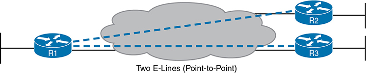
Figure 14-7 Routing Protocol Neighbor Relationships over Metro Ethernet E-Line
Focusing on the E-Lines and ignoring the access links for the most part, think of each E-Line as a subnet. Each router needs an IP address in each subnet, and the subnets need to be unique. All the addresses come from the enterprise’s IP address space. Figure 14-8 shows an example of the addresses, subnets, and three OSPF-learned routes in the routing table of R3.
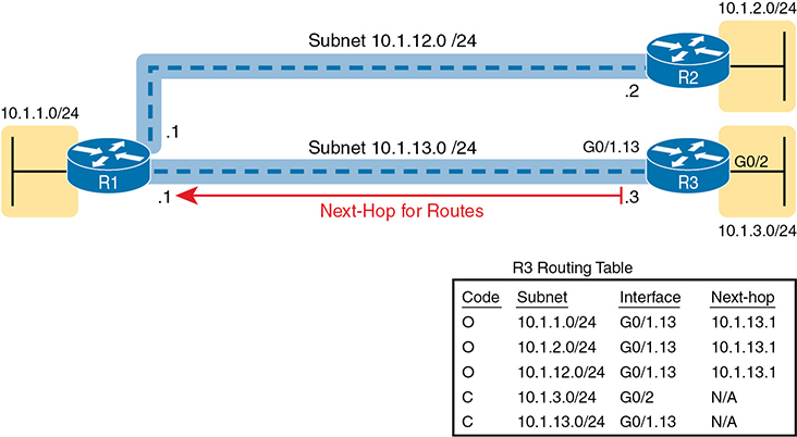
Figure 14-8 Layer 3 Forwarding Between Remote Sites—Through Central Site
Examine the IP routing table in the lower right of the figure, first focusing on the route to subnet 10.1.1.0/24, which is the LAN subnet off router R1. R3’s route points to a next-hop router IP address that is R1’s IP address on the Ethernet WAN, specifically the address on the other side of the E-Line that connects R1 and R3. This route should not be a surprise: for R3 to send packets to a subnet connected to R1, R3 sends the packets to R1. Also, it happens to use a subinterface (G0/1.13), which means that the design is using 802.1Q trunking on the link.
Next, look at R3’s route for subnet 10.1.2.0/24, which supports the fact that R3 cannot send packets directly to R2 with the current WAN design. R3 does not have an E-Line that allows R3 to send frames directly to R2. R3 will not become routing protocol neighbors with R2 either. So, R3 will learn its route for subnet 10.1.2.0/24 from R1, with R1’s 10.1.13.1 address as the next-hop address. As a result, when forwarding packets, R3 will forward packets to R1, which will then forward them over the other E-Line to R2.
Layer 3 Design with E-LAN Service
If you connected four routers to one LAN switch, all in the same VLAN, what would you expect for the IP addresses on those routers? And if all four routers used the same routing protocol, which would become neighbors? Typically, with four routers connected to the same switch, on the same VLAN, using the same routing protocol, normally all four routers would have IP addresses in the same subnet, and all would become neighbors.
On an E-LAN service, the same IP addressing design is used, with the same kinds of routing protocol neighbor relationships. Figure 14-9 shows an example that includes subnets and addresses, plus one route as an example. Note that the four routers connected to the E-LAN service in the center all have addresses in subnet 10.1.99.0/24.
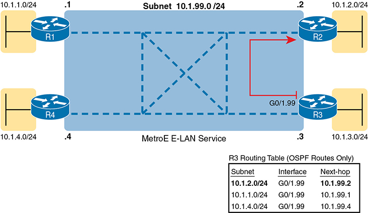
Figure 14-9 Layer 3 Forwarding Between Sites with E-LAN Service
Look at R3’s routing table in the figure, the route from R3 to R2’s LAN subnet (10.1.2.0/24). In this case, R3’s next-hop address is the WAN address on R2 (10.1.99.2), and R3 will send packets (encapsulated in Ethernet frames) directly to R2. Note also that the other two routes in the routing table list the next-hop addresses of R1 (10.1.99.1) and R4 (10.1.99.4).
The details in this first section of the chapter should provide plenty of perspective on how enterprise routers use Ethernet WANs for connectivity. However, if you want a little more detail, the section titled “Ethernet Virtual Circuit Bandwidth Profiles” in Appendix D, “Topics from Previous Editions,” discusses the logic behind how Ethernet WANs use physical links at one speed while supporting services that run at a variety of slower speeds.
Multiprotocol Label Switching (MPLS)
From your CCNA preparation so far, you already understand a lot about the Layer 3 routing, as represented by the packet flowing left to right in Figure 14-10. Each router makes a separate forwarding decision to forward the packet, as shown as steps 1, 2, and 3 in the figure. Each router makes a comparison between the packet’s destination IP address and that router’s IP routing table; the matching IP routing table entry tells the router where to forward the packet next. To learn those routes, the routers typically run some routing protocol.
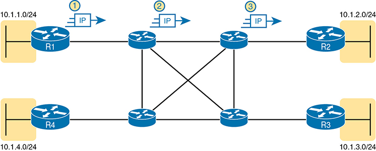
Figure 14-10 Basic IP Routing of IP Packets
MPLS creates a WAN service that routes IP packets between customer sites. The enterprise deploys routers and switches as usual. The SP then creates its own IP network, spanning a large geographic area. The customer can then connect to the MPLS network, with a link from each site, with the SP routing IP packets from one customer site to the other. For instance, in Figure 14-10, the middle four routers could represent the SP’s MPLS network, with the numbered routers on the edges being routers owned by one company.
However, an SP cannot just build a large IP network and connect all its customers to that same IP network because of some issues that arise to support multiple customers at the same time. For instance, many customers will use the same private IP network (for instance, network 10.0.0.0), so the SP’s IP network would learn large numbers of routes to overlapping subnets.
To overcome this and other issues, the SP builds its IP network to also use Multiprotocol Label Switching (MPLS), in particular MPLS VPNs. MPLS VPNs allow the SP to build one large MPLS network, which also creates a private IP-based WAN for each of its customers. With MPLS VPNs, the SP can separate the routes learned from one customer from the routes learned for the next customer; consequently, the SP can support each customer while preventing packets from leaking from one customer to the next.
To give you a little insight as to why MPLS is not just an IP network with routers, internally, the devices in an MPLS network use label switching—hence, the name MPLS. The routers on the edge of the MPLS network add and remove an MPLS header to packets as they enter and exit the MPLS network. The devices inside the MPLS network then use the label field inside that MPLS header when forwarding data across the MPLS network. The choices of the labels to use, along with other related logic, allow the MPLS VPN to create separate VPNs to keep different customers’ traffic separate.
As usual, the discussion of WAN services in this book ignores as much of the SP’s network as possible. For instance, you do not need to know how MPLS labels work. However, because MPLS VPNs create a Layer 3 service, the customer must be more aware of what the SP does than with other WAN servers, so you need to know a few facts about how an MPLS network approaches some Layer 3 functions. In particular, the SP’s MPLS VPN network
Will use a routing protocol to build routing protocol neighbor relationships with customer routers
Will learn customer subnets/routes with those routing protocols
Will advertise a customer’s routes with a routing protocol so that all routers that customer connects to the MPLS VPN can learn all routes as advertised through the MPLS VPN network
Will make decisions about MPLS VPN forwarding, including what MPLS labels to add and remove, based on the customer’s IP address space and customer IP routes
As an aside, MPLS VPNs create a private network by keeping customer data separate, but not by encrypting the data. Some VPN services encrypt the data, expecting that attackers might be able to receive copies of the packets. With MPLS, even though the packets for two customers may pass through the same devices and links inside the MPLS network, MPLS logic can keep the packets separate for each customer.
This second of two major sections of the chapter works through the basics of MPLS, specifically MPLS VPNs. This section first looks at the design, topology, and terminology related to building the customer-facing parts of an MPLS network. It then looks at the impact and issues created by the fact that the MPLS network provides a Layer 3 service.
MPLS VPN Physical Design and Topology
MetroE provides a Layer 2 service by forwarding Layer 2 Ethernet frames. To do that, the SP often uses Ethernet switches at the edge of its network. Those switches are configured to do more than what you learn about Ethernet LAN switches for CCNA, but a LAN switch’s most fundamental job is to forward an Ethernet frame, so it makes sense for MetroE to use an Ethernet switch at the edge of the SP’s MetroE network.
MPLS provides a Layer 3 service in that it promises to forward Layer 3 packets (IPv4 and IPv6). To support that service, MPLS SPs typically use routers at the edge of the MPLS networks because routers provide the function of forwarding Layer 3 packets.
As usual, each WAN technology has its own set of terms and acronyms, so Figure 14-11 shows two important MPLS terms in context: customer edge (CE) and provider edge (PE). Because MPLS requires so much discussion about the devices on the edge of the customer and SP network, MPLS uses specific terms for each. The customer edge device is typically a router, and it sits at a customer site—that is, at a site in the company that is buying the MPLS service. The provider edge devices sit at the edge of the SP’s network, on the other end of the access link.
Next, to appreciate what MPLS does, think back to how routers use their different kinds of physical interfaces and different kinds of data-link protocols. When routing a packet, routers discard an incoming data-link frame’s data-link header and trailer and then build a new data-link header/trailer. That action allows the incoming packet to arrive inside a frame of one data-link protocol and leave out an interface with another data-link protocol.
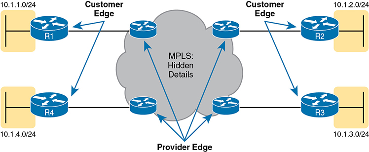
Figure 14-11 MPLS Layer 3 Design, with PE and CE Routers
With MPLS, the fact that the devices are routers, discarding and adding new data-link headers, means that MPLS networks support a variety of access links. The fact that MPLS acts as a Layer 3 service, discarding incoming data-link headers, means that any data-link protocol could in theory be used on MPLS access links. In reality, MPLS does support many types of access links, as shown in Figure 14-12.

Figure 14-12 Popular MPLS Access Link Technologies
The variety of access links available for MPLS networks makes MPLS a great option for building large enterprise networks. For sites that are near MetroE services, especially for sites that need at least 10 Mbps of bandwidth, using MetroE as an access link makes great sense. Then, for sites that are more remote, the carrier may not offer MetroE services to that area, but many carriers can install a serial link to remote sites. Or, common Internet access technologies, like cable and wireless 4G/5G services, can also be used to access an MPLS network.
MPLS and Quality of Service
MPLS stands apart from other WAN services as the first WAN service for which the SP provided effective Quality of Service (QoS) features. You should be able to get a general idea of an MPLS QoS benefit with the following basic example.
IP networks can and often do forward voice traffic in IP packets, called Voice over IP (VoIP). If a WAN service does not provide QoS, that means that the WAN service does not treat one packet any differently than any other packet. With QoS, the SP’s network can treat packets differently, giving some packets (like VoIP) better treatment. For a voice call to sound good, each voice packet must have low loss (that is, few packets are discarded); low one-way delay through the network; and low variation in delay (called jitter). Without QoS, a voice call over an IP network will not sound good.
With a QoS-capable WAN, the customer can mark VoIP packets so that the MPLS network can recognize VoIP packets and treat them better, resulting in better voice call quality. But to make it work correctly, the customer and MPLS provider need to cooperate.
For instance, for VoIP packets traveling left to right in Figure 14-13, router CE1 could be configured with QoS marking tools. Marking tools could recognize VoIP packets and place a specific value in the IP header of VoIP packets (a value called DSCP EF, per the figure). The MPLS WAN provider would then configure its QoS tools to react for packets that have that marking, typically sending that packet as soon as possible. The result: low delay, low jitter, low loss, and a better call quality.
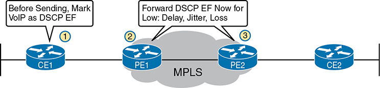
Figure 14-13 MPLS VPN QoS Marking and Reaction in the MPLS WAN
Summarizing the ideas so far, MPLS supports a variety of access links. An enterprise would select the type and speed of access link for each site based on the capacity (bandwidth) required for each site. Beyond that basic connectivity, the enterprise will want to work with the SP to define other features of the service. The customer and SP will need to work through the details of some Layer 3 design choices (as discussed in more depth in the next section). The customer will also likely want to ask for QoS services from the MPLS provider and define those details.
Layer 3 with MPLS VPN
Because MetroE provides a Layer 2 service, the SP has no need to understand anything about the customer’s Layer 3 design. The SP knows nothing about the customer’s IP addressing plan and has no need to participate with routing protocols.
MPLS VPNs take the complete opposite approach. As a Layer 3 service, MPLS must be aware of the customer IP addressing. The SP will even use routing protocols and advertise those customer routes across the WAN. This section takes a closer look at what that means.
First, keep the primary goals in mind. The customer pays good money for a WAN service to deliver data between sites, with certain levels of availability and quality (for instance, low delay, jitter, and loss for VoIP). But to support that base function of allowing packet delivery from each WAN site to the other, the CE routers need to exchange routes with the PE routers in the MPLS network. Additionally, all the CE routers need to learn routes from the other CE routers—a process that relies on the PE routers.
First, the CE routers and the PE router on the ends of the same access link need to exchange routes, as shown in Figure 14-14. The figure shows the CE-PE routing protocol neighbor relationships (as lines with circles on the ends). In this case, the customer chose to use OSPF. However, MPLS allows for many familiar routing protocols on the edge of the MPLS network: RIPv2, EIGRP, OSPF, and even eBGP.
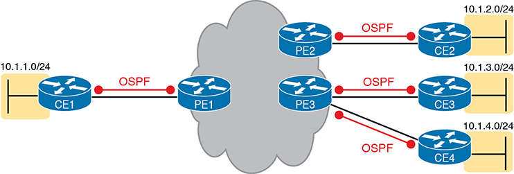
Figure 14-14 Routing Protocol Neighbor Relationships with MPLS Customer Edge Routers
Additionally, all the CE routers need to learn routes from the other CE routers. However, a CE router does not form routing protocol neighbor relationships directly with the other CE routers, as noted in Figure 14-14. Summarizing what does and does not happen:
A CE router does become neighbors with the PE router on the other end of the access link.
A CE router does not become neighbors with other CE routers.
The MPLS network does advertise the customer’s routes between the various PE routers so that the CE routers can learn all customer routes through their PE-CE routing protocol neighbor relationship.
To advertise the customer routes between the PE routers, the PE routers use another routing protocol along with a process called route redistribution. Route redistribution happens inside one router, taking routes from one routing protocol process and injecting them into another. MPLS does route redistribution in the PE routers between the routing protocol used by the customer and a variation of BGP called Multiprotocol BGP (MPBGP). (Redistribution is needed when the PE-CE routing protocol is not BGP.) Figure 14-15 shows the idea.
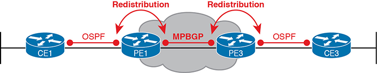
Figure 14-15 MPLS VPN Using Redistribution with MPBGP at PE Router
Just as a quick aside about MPBGP, MPLS VPNs use MPBGP (as opposed to other routing protocols) because MPBGP can advertise routes from multiple customers while keeping the routes logically separated. For instance, continuing the example in Figure 14-15, router PE1 might sit in one PoP but connect to dozens of different customers. Likewise, router PE3 might connect to many of those same customers. MPBGP can advertise routes for all those customers and mark which routes are from which customers so that only the correct routes are advertised to each CE router for different customers.
At the end of the process, for all single enterprises, all the routers can learn routes to all the subnets reachable over the MPLS VPN WAN. WAN routes on the CE routers refer to the neighboring PE router as the next-hop router. Each CE router becomes a routing protocol neighbor with the SP’s PE router on the other end of the access link. Plus, MPLS provides the flexibility to use whatever type of physical access link makes sense for the location at each site, while still connecting to the same MPLS network.
Internet VPNs
To build the Internet, Internet service providers (ISP) need links to other ISPs as well as links to the ISPs’ customers. The Internet core connects ISPs to each other using a variety of highspeed technologies. Additionally, Internet access links connect an ISP to each customer, again with a wide variety of technologies. The combination of ISP networks and customer networks that connect to the ISPs together create the worldwide Internet.
For these customer access links, the technologies need to be inexpensive so that a typical consumer can afford to pay for the service. But businesses can use many of these same technologies to connect to the Internet. Some WAN technologies happen to work particularly well as Internet access technologies. For example, several use the same telephone line installed into most homes by the phone company so that the ISPs do not have to install additional cabling. Some use the TV cabling, whereas others use wireless.
While consumers typically connect to the Internet to reach destinations on the Internet, businesses can also use the Internet as a WAN service. First, the enterprise can connect each business site to the Internet. Then, using virtual private network (VPN) technology, the enterprise can create an Internet VPN. An Internet VPN can keep the enterprise’s packet private through encryption and other means, even while sending the data over the Internet.
This final major section of the chapter discusses some of the basics of Internet access links. The section then details how an enterprise can communicate securely over the Internet, making the public Internet act like a private network, by creating an Internet VPN.
Internet Access
Private WAN technology may be used to access an ISP’s network, including the Ethernet WAN and MPLS technologies discussed earlier in this chapter. Figure 14-16 shows a few of these, just as a visual reminder of these options.
In addition to the traditional services shown in the figure, enterprises can also use Internet access technologies more commonly used by consumers, including DSL, cable, 4G/5G, and fiber Ethernet. The chapter includes this information about Internet access technologies to provide useful background information before getting into Internet VPN topics.
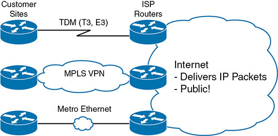
Figure 14-16 Three Examples of Internet Access Links for Companies
Digital Subscriber Line
In the consumer Internet access space, one big speed breakthrough happened with the introduction of the digital subscriber line (DSL). It represented a big technological breakthrough in terms of raw speed in comparison to some older technologies, such as analog modems. These faster speeds available through DSL also changed how people could use the Internet because many of today’s common applications would be unusable with the earlier Internet access technologies (analog modems and Integrated Services Digital Network, or ISDN).
Telephone companies (telcos) greatly influenced the creation of DSL. As a technology, DSL gave telcos a way to offer much faster Internet access speeds. As a business opportunity, DSL gave telcos a way to offer a valuable high-speed Internet service to many of their existing telephone customers, over the same physical phone line already installed, which created a great way for telcos to make money.
Figure 14-17 shows some of the details of how DSL works on a home phone line. The phone can do what it has always done: plug into a phone jack and send analog signals. For the data, a DSL modem connects to a spare phone outlet. The DSL modem sends and receives the data, as digital signals, at higher frequencies, over the same local loop, even at the same time as a telephone call. (Note that the physical installation often uses frequency filters that are not shown in the figure or discussed here.)
Because DSL sends analog (voice) and digital (data) signals on the same line, the telco has to somehow split those signals on the telco side of the connection. To do so, the local loop must be connected to a DSL access multiplexer (DSLAM) located in the nearby telco central office (CO). The DSLAM splits out the digital data over to the router on the lower right in Figure 14-17, which completes the connection to the Internet. The DSLAM also splits out the analog voice signals over to the voice switch on the upper right.

Figure 14-17 Wiring and Devices for a Home DSL Link
Cable Internet
DSL uses the local link (telephone line) from the local telco. Cable Internet instead uses the cabling from what has become the primary competitor to the telco in most markets: the cable company.
Cable Internet creates an Internet access service that, when viewed generally rather than specifically, has many similarities to DSL. Like DSL, cable Internet takes full advantage of existing cabling, using the existing cable TV (CATV) cable to send data. Like DSL, cable Internet uses asymmetric speeds, sending data faster downstream than upstream, which works well for most consumer locations. And cable Internet still allows the normal service on the cable (cable TV), at the same time as the Internet access service is working.
Cable Internet also uses the same general idea for in-home cabling as DSL, just using CATV cabling instead of telephone cabling. The left side of Figure 14-18 shows a TV connected to the CATV cabling, just as it would normally connect. At another cable outlet, a cable modem connects to the same cable. The Internet service flows over one frequency, like yet another TV channel, just reserved for Internet service.

Figure 14-18 Wiring and Devices for a Home Cable Internet Link
Similar to DSL, on the CATV company side of the connection (on the right side of the figure), the CATV company must split out the data and video traffic. Data flows to the lower right, through a router, to the Internet. The video comes in from video dishes for distribution out to the TVs in people’s homes.
Wireless WAN (3G, 4G, LTE, 5G)
Many of you reading this book have a mobile phone that has Internet access. That is, you can check your email, surf the Web, download apps, and watch videos. Many of us today rely on our mobile phones, and the Internet access built in to those phones, for most of our tweets and the like. This section touches on the big concepts behind the Internet access technology connecting those mobile phones.
Mobile phones use radio waves to communicate through a nearby mobile phone tower. The phone has a small radio antenna, and the provider has a much larger antenna sitting at the top of a tower somewhere within miles of you and your phone. Phones, tablet computers, laptops, and even routers (with the correct interface cards) can communicate through to the Internet using this technology, as represented in Figure 14-19.
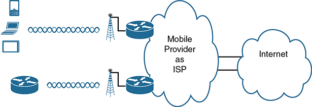
Figure 14-19 Wireless Internet Access Using 3G/4G/5G Technology
The mobile phone radio towers also have cabling and equipment, including routers. The mobile provider builds its own IP network, much like an ISP builds out an IP network. The customer IP packets pass through the IP router at the tower into the mobile provider’s IP network and then out to the Internet.
The market for mobile phones and wireless Internet access for other devices is both large and competitive. As a result, the mobile providers spend a lot of money advertising their services, with lots of names for one service or the other. Frankly, it can be difficult to tell what all the marketing jargon means, but a few terms tend to be used throughout the industry:
Wireless Internet: This general term refers to Internet services from a mobile phone or from any device that uses the same technology.
3G/4G Wireless: Short for third generation and fourth generation, these terms refer to the major changes over time to the mobile phone companies’ wireless networks.
LTE: Long-Term Evolution is a newer and faster technology considered to be part of fourth generation (4G) technology.
5G Wireless: This is the fifth major generation of wireless phone technology.
The takeaway from all this jargon is this: when you hear about wireless Internet services with a mobile phone tower in the picture—whether the device is a phone, tablet, or PC—it is probably a 3G, 4G, or LTE wireless Internet connection, with newer services offering 5G capabilities by 2020 and beyond.
Enterprises can use this same wireless technology to connect to the Internet. For instance, a network engineer can install a 4G wireless card in a router. ISPs team with wireless operators to create contracts for wireless and Internet service.
Fiber (Ethernet) Internet Access
The consumer-focused Internet access technologies discussed in this section use a couple of different physical media. DSL uses the copper wiring installed between the telco CO and the home. Cable uses the copper CATV cabling installed from the cable company to the home. And, of course, wireless WAN technologies do not use cables for Internet access.
The cabling used by DSL and cable Internet uses copper wires, but, comparing different types of physical media, fiber-optic cabling generally supports faster speeds for longer distances. That is, just comparing physical layer technologies across the breadth of networking, fiber-optic cabling supports longer links, and those links often run at equivalent or faster speeds.
Some ISPs now offer Internet access that goes by the name fiber Internet, or simply fiber. To make that work, some local company that owns the rights to install cabling underground in a local area (often a telephone company) installs new fiber-optic cabling. Once the cable plant is in place (a process that often takes years as well as a large budget), the fiber ISP then connects customers to the Internet using the fiber-optic cabling. Often, the fiber uses Ethernet protocols over the fiber. The end result: high-speed Internet to the home, often using Ethernet technology.
Internet VPN Fundamentals
Private WANs have some wonderful security features. In particular, the customers who send data through the WAN have good reason to believe that no attackers saw the data in transit or even changed the data to cause some harm. The private WAN service provider promises to send one customer’s data to other sites owned by that customer, but not to sites owned by other customers, and vice versa.
VPNs try to provide the same secure features as a private WAN while sending data over a network that is open to other parties (such as the Internet). Compared to a private WAN, the Internet does not provide for a secure environment that protects the privacy of an enterprise’s data. Internet VPNs can provide important security features, such as the following:
Confidentiality (privacy): Preventing anyone in the middle of the Internet (man in the middle) from being able to read the data
Authentication: Verifying that the sender of the VPN packet is a legitimate device and not a device used by an attacker
Data integrity: Verifying that the packet was not changed as the packet transited the Internet
Anti-replay: Preventing a man in the middle from copying and later replaying the packets sent by a legitimate user, for the purpose of appearing to be a legitimate user
To accomplish these goals, two devices near the edge of the Internet create a VPN, sometimes called a VPN tunnel. These devices add headers to the original packet, with these headers including fields that allow the VPN devices to make the traffic secure. The VPN devices also encrypt the original IP packet, meaning that the original packet’s contents are undecipherable to anyone who happens to see a copy of the packet as it traverses the Internet.
Figure 14-20 shows the general idea of what typically occurs with a VPN tunnel. The figure shows a VPN created between a branch office router and a Cisco firewall. In this case, the VPN is called a site-to-site VPN because it connects two sites of a company.

Figure 14-20 VPN Tunnel Concepts for a Site-to-Site Intranet VPN
The figure shows the following steps, which explain the overall flow:
Host PC1 (10.2.2.2) on the right sends a packet to the web server (10.1.1.1), just as it would without a VPN.
The router encrypts the packet, adds some VPN headers, adds another IP header (with public IP addresses), and forwards the packet.
An attacker in the Internet copies the packet (called a man-in-the-middle attack). However, the attacker cannot change the packet without being noticed and cannot read the contents of the original packet.
Firewall FW1 receives the packet, confirms the authenticity of the sender, confirms that the packet has not been changed, and then decrypts the original packet.
Server S1 receives the unencrypted packet.
The benefits of using an Internet-based VPN as shown in Figure 14-20 are many. The cost of a high-speed Internet access connection as discussed in the last few pages is usually much less than that of many private WAN options. The Internet is seemingly everywhere, making this kind of solution available worldwide. And by using VPN technology and protocols, the communications are secure.
Site-to-Site VPNs with IPsec
A site-to-site VPN provides VPN services for the devices at two sites with a single VPN tunnel. For instance, if each site has dozens of devices that need to communicate between sites, the various devices do not have to act to create the VPN. Instead, the network engineers configure devices such as routers and firewalls (as shown in Figure 14-20) to create one VPN tunnel. The tunnel endpoints create the tunnel and leave it up and operating all the time, so that when any device at either site decides to send data, the VPN is available. All the devices at each site can communicate using the VPN, receiving all the benefits of the VPN, without requiring each device to create a VPN for themselves.
IPsec defines one popular set of rules for creating secure VPNs. IPsec is an architecture or framework for security services for IP networks. The name itself is not an acronym, but rather a name derived from the title of the RFC that defines it (RFC 4301, “Security Architecture for the Internet Protocol”), more generally called IP Security, or IPsec.
IPsec defines how two devices, both of which connect to the Internet, can achieve the main goals of a VPN as listed at the beginning of this section: confidentiality, authentication, data integrity, and anti-replay. IPsec does not define just one way to implement a VPN, instead allowing several different protocol options for each VPN feature. One of IPsec’s strengths is that its role as an architecture allows it to be added to and changed over time as improvements to individual security functions are made.
The idea of IPsec encryption might sound intimidating, but if you ignore the math—and thankfully, you can—IPsec encryption is not too difficult to understand. IPsec encryption uses a pair of encryption algorithms, which are essentially math formulas, to meet a couple of requirements. First, the two math formulas are a matched set:
One to hide (encrypt) the data
Another to re-create (decrypt) the original data based on the encrypted data
Besides those somewhat obvious functions, the two math formulas were chosen so that if an attacker intercepted the encrypted text but did not have the secret password (called an encryption key), decrypting that one packet would be difficult. In addition, the formulas are also chosen so that if an attacker did happen to decrypt one packet, that information would not give the attacker any advantages in decrypting the other packets.
The process for encrypting data for an IPsec VPN works generally as shown in Figure 14-21. Note that the encryption key is also known as the session key, shared key, or shared session key.

Figure 14-21 Basic IPsec Encryption Process
The four steps highlighted in the figure are as follows:
The sending VPN device (like the remote office router in Figure 14-21) feeds the original packet and the session key into the encryption formula, calculating the encrypted data.
The sending device encapsulates the encrypted data into a packet, which includes the new IP header and VPN header.
The sending device sends this new packet to the destination VPN device (FW1 back in Figure 14-21).
The receiving VPN device runs the corresponding decryption formula, using the encrypted data and session key—the same key value as was used on the sending VPN device—to decrypt the data.
While Figure 14-21 shows the basic encryption process, Figure 14-22 shows a broader view of IPsec VPNs in an enterprise. First, devices use some related VPN technology like Generic Routing Encapsulation (GRE) to create the concept of a tunnel (a virtual link between the routers), with three such tunnels shown in the figure. Without IPsec, each GRE tunnel could be used to forward unencrypted traffic over the Internet. IPsec adds the security features to the data that flows over the tunnel. (Note that the figure shows IPsec and GRE, but IPsec teams with other VPN technologies as well.)
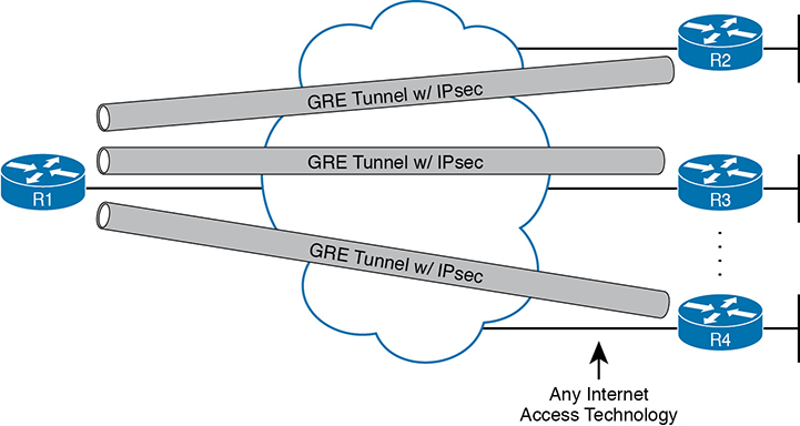
Figure 14-22 Site-to-Site VPN Tunnels with GRE and IPsec
Remote Access VPNs with TLS
A site-to-site VPN exists to support multiple devices at each site and is typically created by devices supported by the IT staff. In contrast, individual devices can dynamically initiate their own VPN connections in cases where a permanent site-to-site VPN does not exist. For instance, a user can walk into a coffee shop and connect to the free Wi-Fi, but that coffee shop does not have a site-to-site VPN to the user’s enterprise network. Instead, the user’s device creates a secure remote access VPN connection back to the enterprise network before sending any data to hosts in the enterprise.
While IPsec and GRE (or other) tunnels work well for site-to-site VPNs, remote access VPNs often use the Transport Layer Security (TLS) protocol to create a secure VPN session.
TLS has many uses today, but most commonly, TLS provides the security features of HTTP Secure (HTTPS). Today’s web browsers support HTTPS (with TLS) as a way to dynamically create a secure connection from the web browser to a web server, supporting safe online access to financial transactions. To do so, the browser creates a TCP connection to server well-known port 443 (default) and then initializes a TLS session. TLS encrypts data sent between the browser and the server and authenticating the user. Then, the HTTP messages flow over the TLS VPN connection.
The built-in TLS functions of a web browser create one secure web browsing session, but each session secures only the data sent in that session. This same TLS technology can be used to create a client VPN that secures all packets from the device to a site by using a Cisco VPN client. The Cisco AnyConnect Secure Mobility Client (or AnyConnect Client for short) is software that sits on a user’s PC and uses TLS to create one end of a VPN remote-access tunnel. As a result, all the packets sent to the other end of the tunnel are encrypted, not just those sent over a single HTTP connection in a web browser.
Figure 14-23 compares the option to create a VPN remote access VPN session from a computer to a site versus for a single HTTPS session. The figure shows a VPN tunnel for PC using the AnyConnect Client to create a client VPN. The AnyConnect Client creates a TLS tunnel to the firewall that has been installed to expect VPN clients to connect to it. The tunnel encrypts all traffic so that PC A can use any application available at the enterprise network on the right.
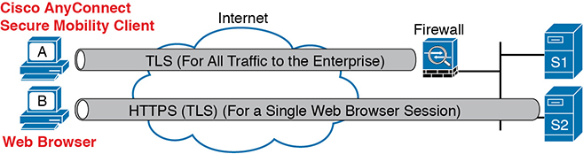
Figure 14-23 Remote Access VPN Options (TLS)
Note that while the figure shows a firewall used at the main enterprise site, many types of devices can be used on the server side of a TLS connection as well.
The bottom of Figure 14-23 shows a client VPN that supports a web application for a single web browser tab. The experience is much like when you connect to any other secure website today: the session uses TLS, so all traffic sent to and from that web browser tab is encrypted with TLS. Note that PC B does not use the AnyConnect Client; the user simply opens a web browser to browse to server S2.
VPN Comparisons
The CCNA 200-301 exam topics mention the terms site-to-site VPN and remote access VPN. To close the section, Table 14-4 lists several key comparison points between the two technologies for easier review and comparison.
Table 14-4 Comparisons of Site-to-Site and Remote Access VPNs
|
Remote Access |
Site-to-Site |
Typical security protocol |
TLS |
IPsec |
Devices supported by one VPN (one or many) |
One |
Many |
Typical use: on-demand or permanent |
On-demand |
Permanent |
Chapter Review
One key to doing well on the exams is to perform repetitive spaced review sessions. Review this chapter’s material using either the tools in the book or interactive tools for the same material found on the book’s companion website. Refer to the “Your Study Plan” element for more details. Table 14-5 outlines the key review elements and where you can find them. To better track your study progress, record when you completed these activities in the second column.
Table 14-5 Chapter Review Tracking
Review Element |
Review Date(s) |
Resource Used: |
Review key topics |
|
Book, website |
Review key terms |
|
Book, website |
Answer DIKTA questions |
|
Book, PTP |
Review memory tables |
|
Book, website |
Review All the Key Topics
Table 14-6 Key Topics for Chapter 14
Key Topic Element |
Description |
Page Number |
Metro Ethernet terminology in context |
||
MetroE service types per MEF |
||
MetroE Ethernet LAN (E-LAN) service concept |
||
MetroE Ethernet Tree (E-Tree) service concept |
||
List |
Ideas about customer Layer 3 addressing and what an MPLS VPN provider needs to know |
|
MPLS terminology in context |
||
List |
Ideas about routing protocol neighbor relationships with MPLS VPN |
|
Concepts of site-to-site VPNs with IPsec and GRE |
||
Concepts of remote access VPNS with TLS |
||
Comparisons between site-to-site and remote access VPNs |