Appendix D. Topics from Previous Editions
Cisco changes the exams, renaming the exams on occasion, and changing the exam numbers every time it changes the exam with a new blueprint, even with a few name changes over the years. As a result, the current CCNA 200-301 exam serves as the eighth separate version of CCNA in its 20-plus year history. At every change to the exams, we create new editions of the books to match the new exam.
We base the books’ contents on Cisco’s exam topics; that is, the book attempts to cover the topics Cisco lists as exam topics. However, the book authoring process does create some challenges, particularly with the balance of what to include in the books and what to leave out.
For instance, when comparing a new exam to the old, I found Cisco had removed some topics—and I might want to keep the content in the book. There are a few reasons why. Sometimes I just expect that some readers will still want to read about that technology. Also, more than a few schools use these books as textbooks, and keeping some of the older-but-still-relevant topics can be a help. And keeping the old material available on each book’s companion website takes only a little extra work, so we do just that.
Some of the older topics that I choose to keep on the companion website are small, so I collect them into this appendix. Other topics happen to have been an entire chapter in a previous edition of the books, so we include those topics each as a separate appendix. Regardless, the material exists here in this appendix, and in the appendixes that follow, for your use if you have a need. But do not feel like you have to read this appendix for the current exam.
The topics in this appendix are as follows:
Cisco Device Hardening
Implementing DHCP
Troubleshooting with IPv4 ACLs
Implementing HSRP
Global Load Balancing Protocol (GLBP)
Implementing Simple Network Management Protocol
Analyzing LAN Physical Standard Choices
Metro Ethernet Virtual Circuits
MPLS VPNs and OSPF
Cisco Device Hardening
The term device hardening refers to making it more difficult for attackers to gain access to the device or to cause problems for the device. This section does not attempt to mention all such details, but it does touch on a few items. (Note that the CCNA Security certification gets into much more detail about router and switch device security.)
In particular, this second major section of the chapter begins by showing how to set some login banner message text for users. The next two topics look at how to secure items unused in the device—unused switch ports on switches and unused software services in both routers and switches.
Configuring Login Banners
Cisco switches and routers can display a variety of banners to a new user when logging in to the switch or router. A banner is simply some text that appears on the screen for the user. You can configure a router or switch to display multiple banners, some before login and some after.
IOS supports three banners based on the first keyword in the banner command. Table D-1 lists the three most popular banners and their typical use.
Table D-1 Banners and Their Typical Use
Banner |
Typical Use |
Message of the Day (MOTD) |
Used for temporary messages that can change from time to time, such as “Router1 down for maintenance at midnight.” |
Login |
Because it is always shown before the user logs in, this message is often used to show warning messages, like “Unauthorized Access Prohibited.” |
Exec |
Because this banner always appears after login, it typically lists device information that outsiders should not see but that internal staff might want to know, for example, the exact location of the device. |
In what may seem like trivia, the banners actually appear in different places based on a couple of conditions. Figure D-1 summarizes when the user sees each of these banners, reading from top to bottom. Console and Telnet users see the banners in the order shown on the left, and SSH users see the banners in the order on the right.

Figure D-1 Banner Sequence Compared: Console/Telnet Versus SSH (Blue Ribbon Set © petrnutil/123RF)
The banner global configuration command can be used to configure all three types of these banners. In each case, the type of banner is listed as the first parameter, with motd being the default option. The first nonblank character after the banner type is called a beginning delimiter character. When a delimiter character is used, the banner text can span several lines, with the CLI user pressing Enter at the end of each line. The CLI knows that the banner has been configured as soon as the user enters the same delimiter character again.
Example D-1 shows the configuration process for all three types of banners from Table D-1, followed by a sample user login session from the console that shows the banners in use. The first configured banner in the example, the MOTD banner, omits the banner type in the banner command as a reminder that motd is the default banner type. The first two banner commands use a # as the delimiter character. The third banner command uses a Z as the delimiter, just to show that any character can be used. Also, the last banner command shows multiple lines of banner text.
Example D-1 Banner Configuration
! Below, the three banners are created in configuration mode. Note that any
! delimiter can be used, as long as the character is not part of the message
! text.

SW1(config)# banner #
Enter TEXT message.  End with the character '#'.
(MOTD) Switch down for maintenance at 11PM Today #
SW1(config)# banner login #
Enter TEXT message.  End with the character '#'.
(Login) Unauthorized Access Prohibited!!!!
#
SW1(config)# banner exec Z
Enter TEXT message.  End with the character 'Z'.
(Exec) Company picnic at the park on Saturday.
 Don't tell outsiders!
Z
SW1(config)# end

! Below, the user of this router quits the console connection, and logs
! back in, seeing the motd and login banners, then the password prompt,
! and then the exec banner.

SW1# quit

SW1 con0 is now available

Press RETURN to get started.

(MOTD) Switch down for maintenance at 11PM Today
(Login) Unauthorized Access Prohibited!!!!

User Access Verification

Username: fred
Password:
(Exec) Company picnic at the park on Saturday.
 Don't tell outsiders!
SW1>
Securing Unused Switch Interfaces
The default settings on Cisco switches work great if you want to buy a switch, unbox it, plug it in, and have it immediately work without any other effort. Those same defaults have an unfortunate side effect for security, however. With all default configuration, an attacker might use unused interfaces to gain access to the LAN. So, Cisco makes some general recommendations to override the default interface settings to make the unused ports more secure, as follows:
Administratively disable the interface using the shutdown interface subcommand.
Prevent VLAN trunking by making the port a nontrunking interface using the switchport mode access interface subcommand.
Assign the port to an unused VLAN using the switchport access vlan number interface subcommand.
Set the native VLAN so that it is not VLAN 1 but instead is an unused VLAN, using the switchport trunk native vlan vlan-id interface subcommand.
Frankly, if you just shut down the interface, the security exposure goes away, but the other tasks prevent any immediate problems if someone else comes around and enables the interface by configuring a no shutdown command.
Implementing DHCP
This section includes DHCP implementation topics from an earlier edition of the book.
DHCP Server Configuration on Routers
A quick Google search on “DHCP server products” reveals that many companies offer DHCP server software. Cisco routers (and some Cisco switches) can also act as a DHCP server with just a little added configuration.
Configuring a Cisco router to act as a DHCP server uses a new configuration concept, one per subnet, called a DHCP pool. All the per-subnet settings go into a per-subnet DHCP pool. The only DHCP command that sits outside the pool is the command that defines the list of addresses excluded from being leased by DHCP. The Cisco IOS DHCP server configuration steps are as follows:
Step 1. Use the ip dhcp excluded-address first last command in global configuration mode to list addresses that should be excluded (that is, not leased by DHCP).
Step 2. Use the ip dhcp pool name command in global configuration mode to both create a DHCP pool for a subnet and to navigate into DHCP pool configuration mode. Then also:
A. Use the network subnet-ID mask or network subnet-ID prefix-length command in DHCP pool configuration mode to define the subnet for this pool.
B. Use the default-router address1 address2… command in DHCP pool configuration mode to define default router IP address(es) in that subnet.
C. Use the dns-server address1 address2… command in DHCP pool configuration mode to define the list of DNS server IP addresses used by hosts in this subnet.
D. Use the lease days hours minutes command in DHCP pool configuration mode to define the length of the lease, in days, hours, and minutes
E. Use the domain-name name command in DHCP pool configuration mode to define the DNS domain name.
F. Use the next-server ip-address command in DHCP pool configuration mode to define the TFTP server IP address used by any hosts (like phones) that need a TFTP server.
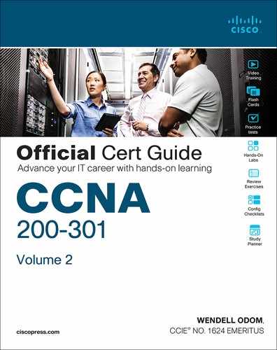
Of course, an example can help, particularly with so many configuration commands required. Figure D-2 shows the organization of the configuration, while sticking to pseudocode rather than the specific configuration commands. (Upcoming Example D-2 shows a matching configuration.) Note that for each of the two LAN subnets, there is a global command to exclude addresses, and then a group of settings for each of two different DHCP pools.
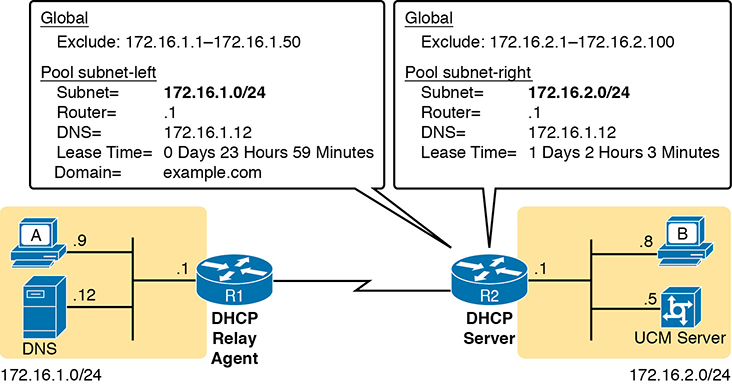
Figure D-2 DHCP Server Configuration Pseudocode
Example D-2 R2 as a DHCP Server Per the Concepts in Figure D-2
ip dhcp excluded-address 172.16.1.1 172.16.1.50
ip dhcp excluded-address 172.16.2.1 172.16.2.100
!
ip dhcp pool subnet-left
 network 172.16.1.0 255.255.255.0
 dns-server 172.16.1.12
 default-router 172.16.1.1
 lease 0 23 59
 domain-name example.com
 next-server 172.16.2.5
!
ip dhcp pool subnet-right
 network 172.16.2.0 /24
 dns-server 172.16.1.12
 default-router 172.16.2.1
 lease 1 2 3
 next-server 172.16.2.5
Focus on subnet 172.16.1.0/24 for a moment: the subnet configured as pool subnet-left. The subnet ID and mask match the subnet ID chosen for that subnet. Then, the global ip dhcp excluded-address command, just above, reserves 172.16.1.1 through 172.16.1.50, so that this DHCP server will not lease these addresses. The server will automatically exclude the subnet ID (172.16.1.0) as well, so this DHCP server will begin leasing IP addresses starting with the .51 address.
Now look at the details for subnet-right. It uses a DHCP pool network command with a prefix style mask. It defines the same DNS server, as does the pool for the other subnet, but a different default router setting, because, of course, the default router in each subnet is different. This pool includes a lease time of 1:02:03 (1 day, 2 hours, and 3 minutes) just as an example.
Also note that both subnets list a TFTP server IP address of the Unified Communications Manager (UCM) server with the next-server command. In most cases, you would find this setting in the pools for subnets in which phones reside.
Finally, note that configuring a router as a DHCP server does not remove the need for the ip helper-address command. If DHCP clients still exist on LANs that do not have a DHCP server, then the routers connected to those LANs still need the ip helper-address command. For example, in Figure D-2, R1 would still need the ip helper-address command on its LAN interface. R2 would not need the command on its LAN interface, because R2 could service those requests, rather than needing to forward the DHCP messages to some other server.
IOS DHCP Server Verification
The IOS DHCP server function has several different show commands. These three commands list most of the details:
show ip dhcp binding: Lists state information about each IP address currently leased to a client
show ip dhcp pool [poolname]: Lists the configured range of IP addresses, plus statistics for the number of currently leased addresses and the high-water mark for leases from each pool
show ip dhcp server statistics: Lists DHCP server statistics
Example D-3 shows sample output from two of these commands, based on the configuration from Figure D-2 and Example D-2. In this case, the DHCP server leased one IP address from each of the pools, one for host A, and one for host B, as shown in the highlighted portions of the output.
Example D-3 Verifying Current Operation of a Router-Based DHCP Server
R2# show ip dhcp binding
Bindings from all pools not associated with VRF:
IP address          Client-ID/              Lease expiration        Type
                    Hardware address/
                    User name
172.16.1.51         0063.6973.636f.2d30.    Oct 12 2012 02:56 AM    Automatic
                    3230.302e.3131.3131.
                    2e31.3131.312d.4661.
                    302f.30
172.16.2.101        0063.6973.636f.2d30.    Oct 12 2012 04:59 AM    Automatic
                    3230.302e.3232.3232.
                    2e32.3232.322d.4769.
                    302f.30
R2# show ip dhcp pool subnet-right
Pool subnet-right :
 Utilization mark (high/low)    : 100 / 0
 Subnet size (first/next)       : 0 / 0
 Total addresses                : 254
 Leased addresses               : 1
 Pending event                  : none
 1 subnet is currently in the pool :
 Current index        IP address range                     Leased addresses
 172.16.2.102         172.16.2.1       - 172.16.2.254      1
Note that the output in Example D-3 does not happen to list the excluded addresses, but it does show the effects. The addresses assigned to the clients end with .51 (host A, subnet 172.16.1.0) and .101 (host B, subnet 172.16.2.0), proving that the server did exclude the addresses as shown in the configuration in Example D-2. The server avoided the .1 through .50 addresses in subnet 172.16.1.0, and the .1 through .100 addresses in subnet 172.16.2.0.
Troubleshooting DHCP Services
To be prepared for the CCNA simlet questions, you have to be ready to predict what symptoms would occur when the network was misconfigured in particular ways. This next section takes a similar approach, pointing out the most typical issues that could be introduced through incorrect or missing configuration, and then discussing what symptoms should happen and how to recognize those problems.
This section begins with a typical look at configuration mistakes and the symptoms that occur with those mistakes. In particular, this section looks at problems with the relay agent’s helper address as well as the IOS DHCP server configuration. This section then looks at non-DHCP problems related to that data plane, breaking the problem into issues between the client and relay agent, and between the relay agent and DHCP server. The final section takes a short look at how a DHCP server prevents duplicate IP addresses between hosts that use static IP addresses and those that use DHCP.
DHCP Relay Agent Configuration Mistakes and Symptoms
One configuration mistake that prevents DHCP client from leasing an IP address is the misconfiguration or the omission of the ip helper-address interface subcommand on the router acting as the DHCP relay agent. The relay agent takes the incoming DHCP message, changes the destination address of the packet to be the address on the ip helper-address address command, and forwards the packet to that address. If the command is missing, the router does not attempt to forward the DHCP messages at all; if it is incorrect, the relay agent forwards the DHCP packets, but they never arrive at the actual DHCP server.
The main problem symptom in this case is the failure of a DHCP client to lease an address. If you can identify a client that has a problem, and you know what VLAN or subnet in which that host resides, you can then work to identify any routers connected to that subnet, to find and correct the ip helper-address subcommands.
Beyond that step, this list summarizes a few other related points.
The DHCP relay agent feature is needed on interfaces only if the DHCP server is on a different subnet; it is not needed if the DHCP server is on the same subnet as the client.
On routers with VLAN trunks (with a router-on-a-stick [ROAS] subinterface configuration), the subinterfaces also need an ip helper-address command (assuming they meet the first criteria in this list).
If an exam question does not allow you to look at the configuration, use the show ip interface [type number] command to view the ip helper-address setting on an interface.
About that last point, Example D-4 shows an example of the show ip interface g0/0 command. In this case, the interface has been configured with the ip helper-address 172.16.2.11 command; the show command output basically restates that fact. Note that if there were no ip helper-address configured on the interface, the text would instead read “Helper address is not set.”
Example D-4 Listing the Current Helper Address Setting with show ip interface
R1# show ip interface g0/0
GigabitEthernet0/0 is up, line protocol is up
  Internet address is 182.16.1.1/24
  Broadcast address is 255.255.255.255
  Address determined by non-volatile memory
  MTU is 1500 bytes
  Helper address is 172.16.2.11
! Lines omitted for brevity (about 20 lines)
IOS DHCP Server Configuration Mistakes and Symptoms
When using an IOS DHCP server, from a troubleshooting perspective, break issues into two broad categories: those that prevent DHCP clients from leasing an address, and those that allow the lease but provide incorrect settings to the client.
First, the primary configuration mistake that causes a failure in the DHCP lease process is the misconfiguration of the network command. The problem revolves around these key facts:
The packet from the relay agent to the DHCP server uses the relay agent’s interface IP address as the source IP address in the forwarded DHCP message.
The DHCP server compares that source IP address in the received DHCP packet to the network commands in its DHCP pools to find the right pool.
Each network subnet mask command implies a range of addresses, just like any other IP network or subnet shown with a subnet mask.
If the source IP address of the packet is not in the range of addresses implied by any network command in all the pools, the DHCP server has no pool to use for that request. The DHCP server does not know how to respond, so it does not reply at all.
As an example of that failure, consider the configuration shown in Figure D-3. The left side shows the configuration on R1, a DHCP relay agent that has two interfaces configured with the ip helper-address 172.16.2.11 command. The DHCP server configuration on the right lists two pools, intended as one pool for each subnet off Router R1. However, the network 172.16.3.0 /25 command implies an address range of 172.16.3.0 to 172.16.3.127, and the relay agent’s interface address of 172.16.3.254 is not within that range of numbers. The solution would be to correct the DHCP server’s network command to use a /24 mask.

Figure D-3 An Example Misconfiguration of a DHCP Pool network Command
While you ultimately need to find this kind of problem and fix the configuration, on the exam you need to be ready to discover the root cause based on symptoms and show commands as well. So, when troubleshooting DHCP issues, and the client fails to lease an address, look at the IOS DHCP server’s network commands. Calculate the range of IP addresses as if that command were defining a subnet. Then compare that range of addresses by the network command in each pool to the interface addresses on the DHCP relay agent routers. Every relay agent interface (that is, every interface with an ip helper-address command configured) should be included in a pool defined at the IOS DHCP server.
The DHCP server can also be misconfigured in a way that allows the lease of an address, but then causes other problems. If the lease process works, but the rest of the parameters given to the client are incorrect or missing, the client could operate, but operate poorly. This list summarizes the kinds of mistakes and the resulting symptoms:
With the DNS server IP addresses incorrectly configured on the server (or omitted), hosts would fail to resolve hostnames into their associated IP addresses.
With the default gateway IP address incorrectly configured on the server (or omitted), hosts could not communicate outside the local subnet.
With the TFTP server IP address incorrectly configured (or omitted), an IP phone would fail to correctly load its configuration.
IP Connectivity from DHCP Relay Agent to DHCP Server
For the DHCP process to work with a centralized server, IP broadcast packets must flow between the client and relay agent, and IP unicast packets must flow between the relay agent and the DHCP server. Any problem that prevents the flow of these packets also prevents DHCP from working.
For perspective, consider the topology in Figure D-4, which again shows the relay agent on the left and the DHCP server on the right. The server uses IP address 172.16.2.11, and the relay agent uses interface address 172.16.1.1. Any failure that prevents the flow of IP packets between those two IP addresses would prevent host A from leasing an IP address.
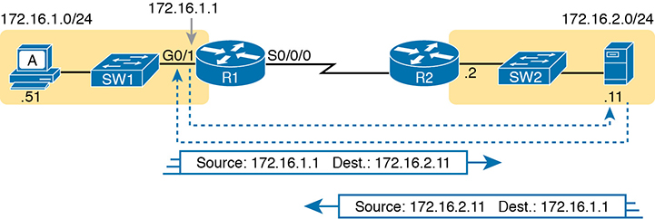
Figure D-4 Addresses Used Between Relay Agent and Server
Remember that the IP addresses used on the packets between the relay agent and server, and know that you may need to troubleshoot IP routing to ensure those packets can be delivered.
LAN Connectivity Between the DHCP Client and Relay Agent
You might encounter a network environment where DHCP messages on the same LAN as the DHCP client all show a destination IP address of 255.255.255.255. What does that really mean? When a packet uses this 255.255.255.255 address:
The address is called the local broadcast address.
Packets sent to this address are not forwarded as-is by routers.
On a LAN, the sender of an IP local broadcast packet encapsulates these IP packets in an Ethernet frame with an Ethernet broadcast destination address (FFFF.FFFF.FFFF), so the LAN broadcasts the frame.
As a result of the logic in these steps, the broadcast DHCP messages can easily flow between the client and router, as long as the LAN works.
Summary of DHCP Troubleshooting
In summary, as a study tool, the following list summarizes the key troubleshooting ideas from this section on troubleshooting DHCP:
Step 1. If using a centralized DHCP server, at least one router on each remote subnet that has DHCP clients must act as DHCP relay agent, and have a correctly configured ip helper-address address subcommand on the interface connected to that subnet.
Step 2. If using a centralized IOS DHCP server, make sure the DHCP pools’ network commands match the entire network’s list of router interfaces that have an ip helper-address command pointing to this DHCP server.
Step 3. Troubleshoot for any IP connectivity issues between the DHCP relay agent and the DHCP server, using the relay agent interface IP address and the server IP address as the source and destination of the packets.
Step 4. Troubleshoot for any LAN issues between the DHCP client and the DHCP relay agent.
Also, as one final note about DHCP in the real world, DHCP might seem dangerous at this point, with all the focus on potential problems in this section, combined with the importance of DHCP and its use by most end user devices. However, DHCP has some great availability features. First, most DHCP servers set their lease times for at least a few days, often a week, or maybe longer. Combined with that, the DHCP protocol has several processes through which the client reconfirms the existing lease with the server, and re-leases the same IP address in advance of the expiration of the lease. Clients do not simply wait until the moment the lease would expire to then contact the DHCP server, hoping it is available. So the network can have outages, and DHCP clients that have already leased an address can continue to work without any problem.
Detecting Conflicts with Offered Versus Used Addresses
Beyond troubleshooting the types of problems that would prevent DHCP from working, the IOS DHCP server tries to prevent another type of problem: assigning IP addresses with DHCP when another host tries to statically configure that same IP address. Although the DHCP server configuration clearly lists the addresses in the pool, plus those to be excluded from the pool, hosts can still statically configure addresses from the range inside the DHCP pool. In other words, no protocols prevent a host from statically configuring and using an IP address from within the range of addresses used by the DHCP server.
Knowing that some host might have statically configured an address from within the range of addresses in the DHCP pool, both DHCP servers and clients try to detect such problems, called conflicts, before the client uses a newly leased address.
DHCP servers detect conflicts by using pings. Before offering a new IP address to a client, the DHCP server first pings the address. If the server receives a response to the ping, some other host must already be using the address, which lets the server know a conflict exists. The server notes that particular address as being in conflict, and the server does not offer the address, moving on to the next address in the pool.
The DHCP client can also detect conflicts, but instead of using ping, it uses ARP. In the client case, when the DHCP client receives from the DHCP server an offer to use a particular IP address, the client sends an Address Resolution Protocol (ARP) request for that address. If another host replies, the DHCP client has found a conflict.
Example D-5 lists output from the router-based DHCP server on R2, after host B detected a conflict using ARP. Behind the scenes, host B used DHCP to request a lease, with the process working normally until host B used ARP and found some other device already used 172.16.2.102. At that point, host B then sent a DHCP message back to the server, rejecting the use of address 172.16.2.102. The example shows the router’s log message related to host B’s discovery of the conflict, and a show command that lists all conflicted addresses.
Example D-5 Displaying Information About DHCP Conflicts in IOS
*Oct 16 19:28:59.220: %DHCPD-4-DECLINE_CONFLICT: DHCP address conflict:
  client 0063.6973.636f.2d30.3230.302e.3034.3034.2e30.3430.342d.4769.302f.30
    declined 172.16.2.102.
R2# show ip dhcp conflict
IP address        Detection method   Detection time          VRF
172.16.2.102      Gratuitous ARP     Oct 16 2012 07:28 PM
The show ip dhcp conflict command lists the method through which the server added each address to the conflict list: either gratuitous ARP, as detected by the client, or ping, as detected by the server. The server avoids offering these conflicted addresses to any future clients, until the engineer uses the clear ip dhcp conflict command to clear the list.
Troubleshooting with IPv4 ACLs
The use of IPv4 ACLs makes troubleshooting IPv4 routing more difficult. Any data plane troubleshooting process can include a catchall phrase to include checking for ACLs. A network can have all hosts working, DHCP settings correct, all LANs working, all router interfaces working, and all routers having learned all routes to all subnets—and ACLs can still filter packets. Although ACLs provide that important service of filtering some packets, ACLs can make the troubleshooting process that much more difficult.
This third of the three major sections of this chapter focuses on troubleshooting in the presence of IPv4 ACLs. It breaks the discussion into two parts. The first part gives advice about common problems you might see on the exam, and how to find those with show commands and some analysis. The second part then looks at how ACLs impact the ping command.
Analyzing ACL Behavior in a Network
ACLs cause some of the biggest challenges when troubleshooting problems in real networking jobs. The packets created by commands like ping and traceroute do not exactly match the fields in packets created by end users. The ACLs sometimes filter the ping and traceroute traffic, making the network engineer think some other kind of problems exists when no problems exist at all. Or, the problem with the end-user traffic really is caused by the ACL, but the ping and traceroute traffic works fine, because the ACL matches the end-user traffic with a deny action but matches the ping and traceroute traffic with a permit action.
As a result, much of ACL troubleshooting requires thinking about ACL configuration versus the packets that flow in a network, rather than using a couple of IOS commands that identify the root cause of the problem. The show commands that help are those that give you the configuration of the ACL, and on what interfaces the ACL is enabled. You can also see statistics about which ACL statements have been matched. And using pings and traceroutes can help—as long as you remember that ACLs may apply different actions to those packets versus the end-user traffic.
The following phrases the ACL troubleshooting steps into a list for easier study. The list also expands on the idea of analyzing each ACL in step 3. None of the ideas in the list are new compared to this chapter and the previous chapter, but it acts more as a summary of the common issues:
Step 1. Determine on which interfaces ACLs are enabled, and in which direction (show running-config, show ip interfaces).
Step 2. Find the configuration of each ACL (show access-lists, show ip access-lists, show running-config).
Step 3. Analyze the ACLs to predict which packets should match the ACL, focusing on the following points:
A. Misordered ACLs: Look for misordered ACL statements. IOS uses first-match logic when searching an ACL.
B. Reversed source/destination addresses: Analyze the router interface, the direction in which the ACL is enabled, compared to the location of the IP address ranges matched by the ACL statements. Make sure the source IP address field could match packets with that source IP address, rather than the destination, and vice versa for the destination IP address field.
C. Reversed source/destination ports: For extended ACLs that reference UDP or TCP port numbers, continue to analyze the location and direction of the ACL versus the hosts, focusing on which host acts as the server using a well-known port. Ensure that the ACL statement matches the correct source or destination port depending on whether the server sent or will receive the packet.
D. Syntax: Remember that extended ACL commands must use the tcp and udp keywords if the command needs to check the port numbers.
E. Syntax: Note that ICMP packets do not use UDP or TCP; ICMP is considered to be another protocol matchable with the icmp keyword (instead of tcp or udp).
F. Explicit deny any: Instead of using the implicit deny any at the end of each ACL, use an explicit configuration command to deny all traffic at the end of the ACL so that the show command counters increment when that action is taken.
G. Dangerous inbound ACLs: Watch for inbound ACLs, especially those with deny all logic at the end of the ACL. These ACLs may discard incoming overhead protocols, like routing protocol messages.
H. Standard ACL location: Standard ACLs enabled close to the source of matched addresses can discard the packets as intended, but also discard packets that should be allowed through. Always pay close attention to the requirements of the ACL in these cases.
The first two steps are important for simlet questions in case you are not allowed to look at the configuration; you can use other show commands to determine all the relevant ACL configuration. The next few pages show some of the related commands and how they can uncover some of the issues described in the just-completed ACL troubleshooting checklist.
ACL Troubleshooting Commands
If you suspect ACLs are causing a problem, the first problem-isolation step is to find the location and direction of the ACLs. The fastest way to do this is to look at the output of the show running-config command and to look for ip access-group commands under each interface. However, in some cases, enable mode access may not be allowed, and show commands are required. Instead, use the show ip interfaces command to find which ACLs are enabled on which interfaces, as shown in Example D-6.
Example D-6 Sample show ip interface Command
R1> show ip interface s0/0/1
Serial0/0/1 is up, line protocol is up
  Internet address is 10.1.2.1/24
  Broadcast address is 255.255.255.255
  Address determined by setup command
  MTU is 1500 bytes
  Helper address is not set
  Directed broadcast forwarding is disabled
  Multicast reserved groups joined: 224.0.0.9
  Outgoing access list is not set
  Inbound access list is 102
! roughly 26 more lines omitted for brevity
Note that the command output lists whether an ACL is enabled, in both directions, and which ACL it is. The example shows an abbreviated version of the show ip interface S0/0/1 command, which lists messages for just this one interface. The show ip interface command would list the same messages for every interface in the router.
Step 2 of the ACL troubleshooting checklist then says that the contents of the ACL must be found. Again, the quickest way to look at the ACL is to use the show running-config command. If it’s not available, the show access-lists and show ip access-lists commands list the same details shown in the configuration. These commands also list a useful counter that lists the number of packets that have matched each line in the ACL. Example D-7 shows an example.
Example D-7 show ip access-lists Command Example
R1# show ip access-lists
Extended IP access list 102
   10 permit ip 10.1.2.0 0.0.0.255 10.1.4.0 0.0.1.255 (15 matches)
The counter can be very useful for troubleshooting. If you can generate traffic that you think should match a particular line in an ACL, then you should see the matches increment on that counter. If you keep generating traffic that should match, but that line’s counter never goes up, then those packets do not match that line in that ACL. Those packets could be matching an earlier line in the same ACL, or might not even be reaching that router (for any reason).
After the locations, directions, and configuration details of the various ACLs have been discovered in steps 1 and 2, the hard part begins—analyzing what the ACL really does. For example, one of the most common tasks you will do is to look at the address fields and decide the range of addresses matched by that field. Remember, for an ACL that sits in a router configuration, you can easily find the address range. The low end of the range is the address (the first number), and the high end of the range is the sum of the address and wildcard mask. For instance, with ACL 102 in Example D-7, which is obviously configured in some router, the ranges are as follows:
Source 10.1.2.0, wildcard 0.0.0.255: Matches from 10.1.2.0 through 10.1.2.255
Destination 10.1.4.0, wildcard 0.0.1.255: Matches from 10.1.4.0 through 10.1.5.255
The next few pages work through some analysis of a few of the items from step 3 in the troubleshooting checklist.
Example Issue: Reversed Source/Destination IP Addresses
IOS cannot recognize a case in which you attempt to match the wrong addresses in the source or destination address field. So, be ready to analyze the enabled ACLs and their direction versus the location of different subnets in the network. Then ask yourself about the packets that drive that ACL: what could the source and destination addresses of those packets be? And does the ACL match the correct address ranges, or not?
For example, consider Figure D-5, a figure that will be used in several troubleshooting examples in this chapter. The requirements for the next ACL follow the figure.
Figure D-5 Example Network Used in IPv4 ACL Troubleshooting Examples
For this next ACL, the requirements ask that you allow and prevent various flows, as follows:
Allow hosts in subnet 10.3.3.0/25 and subnet 10.1.1.0/24 to communicate
Prevent hosts in subnet 10.4.4.0/23 and subnet 10.1.1.0/24 from communicating
Allow all other communications between hosts in network 10.0.0.0
Prevent all other communications
Example D-8 shows the ACL used in this case on R2. At first glance, it meets all those requirements straight down the list.
Example D-8 Troubleshooting Example 2 per Step 3B: Source and Destination Mismatch
R2# show ip access-lists
Standard IP access list Step3B
   10 permit 10.3.3.0 0.0.0.127
   20 deny 10.4.4.0 0.0.1.255
   30 permit 10.0.0.0 0.255.255.255 (12 matches)
R2#
R2# show ip interface G0/1 | include Inbound
   Inbound access list is Step3B
The problem in this case is that the ACL has been enabled on R2’s G0/1 interface, inbound. Per the figure, packets coming from a source address in subnets 10.3.3.0/25 and 10.4.4.0/23 should be forwarded out R2’s G0/1 interface, rather than coming in that interface. So, do not let the matching logic in the ACL that perfectly mirrors the requirements fool you; make sure and check the location of the ACL, direction, and the location of the IP addresses.
Note that step 3C suggests a similar issue regarding matching well-known ports with TCP and UDP. The earlier section in this chapter titled “Matching TCP and UDP Port Numbers” has already discussed those ideas in plenty of detail. Just make sure to check where the server sits versus the location and direction of the ACL.
Steps 3D and 3E: Common Syntax Mistakes
Steps 3D and 3E describe a couple of common syntax mistakes. First, to match a TCP port in an ACL statement, you must use a tcp protocol keyword instead of ip or any other value. Otherwise, IOS rejects the command as having incorrect syntax. Same issue with trying to match UDP ports: a udp protocol keyword is required.
To match ICMP, IOS includes an icmp protocol keyword to use instead of tcp or udp. In fact, the main conceptual mistake is to think of ICMP as an application protocol that uses either UDP or TCP; it uses neither. To match all ICMP messages, for instance, use the permit icmp any any command in an extended named ACL.
Example Issue: Inbound ACL Filters Routing Protocol Packets
A router bypasses outbound ACL logic for packets the router itself generates. That might sound like common sense, but it is important to stop and think about that fact in context. A router can have an outgoing ACL, and that ACL can and will discard packets that the router receives in one interface and then tries to forward out some other interface. But if the router creates the packet, for instance, for a routing protocol message, the router bypasses the outbound ACL logic for that packet.
However, a router does not bypass inbound ACL logic. If an ACL has an inbound ACL enabled, and a packet arrives in that interface, the router checks the ACL. Any and all IPv4 packets are considered by the ACL—including important overhead packets like routing protocol updates.
For example, consider a seemingly good ACL on a router, like the step 3G ACL in Example D-9. That ACL lists a couple of permit commands, and has an implicit deny any at the end of the list. At first, it looks like any other reasonable ACL.
Example D-9 Troubleshooting Example 2 per Step 3G: Filtering RIP by Accident
R1# show ip access-lists
Standard IP access list Step3G
   10 permit host 10.4.4.1
   20 permit 10.3.3.0 0.0.0.127 (12 matches)
! using the implicit deny to match everything else
R1#
! On router R1:
R1# show ip interface G0/2 | include Inbound
   Inbound access list is Step3G
Now look at the location and direction (inbound on R1, on R1’s G0/2) and consider that location versus the topology Figure D-5 for a moment. None of those permit statements match the RIP updates sent by R2, sent out R2’s G0/1 interface toward R1. RIP messages use UDP (well-known port 520), and R2’s G0/1 interface is 10.2.2.2 per the figure. R1 would match incoming RIP messages with the implicit deny all at the end of the list. The symptoms in this case, assuming only that one ACL exists, would be that R1 would not learn routes from R2, but R2 could still learn RIP routes from R1.
Of the three routing protocols discussed in the ICND1 and ICND2 books, RIPv2 uses UDP as a transport, while OSPF and EIGRP do not even use a transport protocol. As a result, to match RIPv2 packets with an ACL, you need the udp keyword and you need to match well-known port 520. OSPF and EIGRP can be matched with special keywords as noted in Table D-2. The table also list the addresses used by each protocol.
Table D-2 Key Fields for Matching Routing Protocol Messages
Protocol |
Source IP Address |
Destination IP Addresses |
ACL Protocol Keyword |
RIPv2 |
Source interface |
224.0.0.9 |
udp (port 520) |
OSPF |
Source interface |
224.0.0.5, 224.0.0.6 |
ospf |
EIGRP |
Source interface |
224.0.0.10 |
eigrp |
Example D-10 shows a sample ACL with three lines, one to match each routing protocol, just to show the syntax. Note that in this case, the ACL matches the address fields with the any keyword. You could include lines like these in any inbound ACL to ensure that routing protocol packets would be permitted.
Example D-10 Example ACL that Matches all RIPv2, OSPF, and EIGRP with a Permit
R1# show ip access-lists
ip access-list extended RoutingProtocolExample
  10 permit udp any any eq 520
  20 permit ospf any any
  30 permit eigrp any any
  remark a complete ACL would also need more statements here
R1#
ACL Interactions with Router-Generated Packets
Routers bypass outbound ACL logic for packets generated by that same router. This logic helps avoid cases in which a router discards its own overhead traffic. This logic applies to packets that a router creates for overhead processes like routing protocols, as well as for commands, like ping and traceroute. This section adds a few perspectives about how ACLs impact troubleshooting, and how this exception to outbound ACL logic applies, particularly commands used from the router CLI.
Local ACLs and a Ping from a Router
For the first scenario, think about a ping command issued by a router. The command generates packets, and the router sends those packets (holding the ICMP echo request messages) out one of the router interfaces, and typically some ICMP echo reply messages are received back. As it turns out, not all ACLs will attempt to filter those packets.
As a backdrop to discuss what happens, Figure D-6 illustrates a simple network topology with two routers connected to a serial link. Note that in this figure four IP ACLs exist, named A, B, C, and D, as noted by the thick arrows in the drawing. That is, ACL A is an outbound ACL on R1’s S0/0/0, ACL B is an inbound ACL on R2’s S0/0/1, and so on.

Figure D-6 Sample Network with IP ACLs in Four Locations
As an example, consider a ping command issued from R1’s CLI (after a user connects to R1’s CLI using SSH). The ping command pings server S1’s IP address. The IPv4 packets with the ICMP messages flow from R1 to S1 and back again. Which of those four ACLs could possibly filter the ICMP Echo Request toward S1, and the ICMP Echo Reply back toward R1?
Routers bypass their own outbound ACLs for packets generated by the router, as shown in Figure D-7. Even though ACL A exists as an outgoing ACL on Router R1, R1 bypasses its own outgoing ACL logic of ACL A for the ICMP Echo Requests generated by R1.
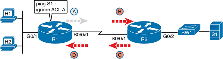
Figure D-7 R1 Ignores Outgoing ACL for Packets Created by Its Own ping Command
Router Self-Ping of a Serial Interface IPv4 Address
The previous example uses a router’s ping command when pinging a host. However, network engineers often need to ping router IP addresses, including using a self-ping. The term self-ping refers to a ping of a device’s own IPv4 address. And for point-to-point serial links, a self-ping actually sends packets over the serial link, which causes some interesting effects with ACLs.
When a user issues a self-ping for that local router’s serial IP address, the router actually sends the ICMP echo request out the link to the other router. The neighboring router then receives the packet and routes the packet with the ICMP echo request back to the original router. Figure D-8 shows an example of a self-ping (ping 172.16.4.1) of Router R1’s own IP address on a point-to-point serial link, with the ICMP echo request out the link to Router R2. At step 2, R2 treats it like any other packet not destined for one of R2’s own IPv4 addresses: R2 routes the packet. Where? Right back to Router R1, as shown in the figure.
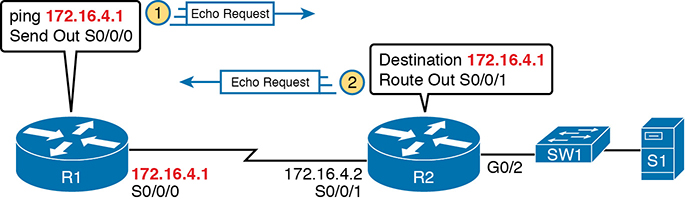
Figure D-8 The First Steps in a Self-Ping on R1, for R1’s S0/0/0 IP Address
Now think about those four ACLs in the earlier figures compared to Figure D-8. R1 generates the ICMP echo request, so R1 bypasses outbound ACL A. ACLs B, C, and D could filter the packet. Note that the packet sent by R2 back to R1 is not generated by R2 in this case; R2 is just routing R1’s original packet back to R1.
A self-ping of a serial interface actually tests many parts of a point-to-point serial link, as follows:
The link must work at Layers 1, 2, and 3. Specifically, both routers must have a working (up/up) serial interface, with correct IPv4 addresses configured.
ACLs B, C, and D must permit the ICMP echo request and reply packets.
So, when troubleshooting, if you choose to use self-pings and they fail, but the serial interfaces are in an up/up state, do not forget to check to see whether the ACLs have filtered the Internet Control Management Protocol (ICMP) traffic.
Router Self-Ping of an Ethernet Interface IPv4 Address
A self-ping of a router’s own Ethernet interface IP address works a little like a self-ping of a router’s serial IP address, but with a couple of twists:
Like with serial interface, the local router interface must be working (in an up/up state); otherwise, the ping fails.
Unlike serial interfaces, the router does not forward the ICMP messages physically out the interface, so security features on neighboring switches (like port security) or routers (like ACLs) cannot possibly filter the messages used by the ping command.
Like serial interfaces, an incoming IP ACL on the local router does process the router self-ping of an Ethernet-based IP address.
Figure D-9 walks through an example. In this case, R2 issues a ping 172.16.2.2 command to ping its own G0/2 IP address. Just like with a self-ping on serial links, R2 creates the ICMP echo request. However, R2 basically processes the ping down its own TCP/IP stack and back up again, with the ICMP echo never leaving the router’s Ethernet interface. R2 does check the Ethernet interface status, showing a failure if the interface is not up/up. R2 does not apply outbound ACL logic to the packet, because R2 created the packet, but R2 will apply inbound ACL logic to the packet, as if the packet had been physically received on the interface.
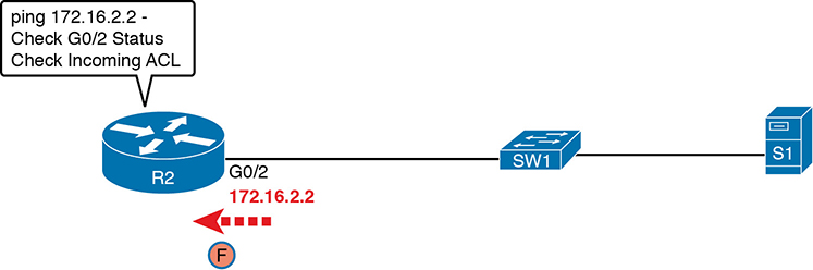
Figure D-9 Self-Ping of a Router’s Ethernet Address
Implementing HSRP
The goal of this section is to show enough of the operation of each tool to reinforce your understanding of configuring the basic functions of HSRP.
Configuring and Verifying Basic HSRP
HSRP configuration requires only one command on the two (or more) routers that want to share default router responsibilities with HSRP: the standby group ip virtual-ip interface subcommand. The first value defines the HSRP group number, which must match on both routers. The group number lets one router support multiple HSRP groups at a time on the same interface, and it allows the routers to identify each other based on the group. The command also configures the virtual IP address shared by the routers in the same group; the virtual IP address is the address the hosts in the VLAN use as their default gateway.
Example D-11 shows a configuration example where both routers use group 1, with virtual IP address 10.1.1.1, with the standby 1 ip 10.1.1.1 interface subcommand.
Example D-11 HSRP Configuration on R1 and R2, Sharing IP Address 10.1.1.1
R1# show running-config
! Lines omitted for brevity
interface GigabitEthernet0/0
 ip address 10.1.1.9 255.255.255.0
 standby version 2
 standby 1 ip 10.1.1.1
 standby 1 priority 110
 standby 1 name HSRP-group-for-book
! The following configuration, on R2, is identical except for the HSRP priority and
! the interface IP address
R2# show running-config
! Lines omitted for brevity
interface GigabitEthernet0/0
 ip address 10.1.1.129 255.255.255.0
 standby version 2
 standby 1 ip 10.1.1.1
 standby 1 name HSRP-group-for-book
The configuration shows other optional parameters, as well. For instance, R1 has a priority of 110 in this group, and R2 defaults to 100. With HSRP, if the two routers are brought up at the same time, the router with the higher priority wins the election to become the active router. The configuration also shows a name that can be assigned to the group (when using show commands) and a choice to use HSRP Version 2. (This chapter provides more details on these settings in the coming pages.)
Once configured, the two routers negotiate the HSRP settings and choose which router will currently be active and which will be standby. With the configuration as shown, R1 will win the election and become active because of its higher (better) priority. Both routers reach the same conclusion, as confirmed with the output of the show standby brief command on both R1 and R2 in Example D-12.
Example D-12 HSRP Status on R1 and R2 with show standby brief
! First, the group status as seen from R1
R1# show standby brief
                     P indicates configured to preempt.
                     |
Interface   Grp  Pri P State   Active          Standby          Virtual IP
Gi0/0       1    110   Active  local           10.1.1.129       10.1.1.1
! The output here on R2 shows that R2 agrees with R1.
R2# show standby brief
                     P indicates configured to preempt.
                     |
Interface   Grp  Pri P State   Active          Standby          Virtual IP
Gi0/0       1    100   Standby 10.1.1.9        local            10.1.1.1
The show standby brief command packs a lot of detail in the output, so take your time and work through the highlighted fields. First, look at the Grp column for each command. This lists the HSRP group number, so when looking at output from multiple routers, you need to look at the lines with the same group number to make sure the data relates to that one HSRP group. In this case, both routers have only one group number (1), so it is easy to find the information.
Each line of output lists the local router’s view of the HSRP status for that group. In particular, based on the headings, the show standby brief command identifies the following:
Interface: The local router’s interface on which the HSRP group is configured
Grp: The HSRP group number
Pri: The local router’s HSRP priority
State: The local router’s current HSRP state
Active: The interface IP address of the currently active HSRP router (or “local” if the local router is HSRP active)
Standby: The interface IP address of the currently standby HSRP router (or “local” if the local router is HSRP standby)
Virtual IP: The virtual IP address defined by this router for this group
For instance, following the highlighted text in Example D-12, R2 believes that its own current state is standby, that the router with interface address 10.1.1.9 is active (which happens to be Router R1), with a confirmation that the “local” router (R2, on which this command was issued) is the standby router.
In comparison, the show standby command (without the brief keyword) lists a more detailed description of the current state, while repeating many of the facts from the show standby brief command. Example D-13 shows an example of the new information with the show standby command, listing several counters and timers about the HSRP protocol itself, plus the virtual MAC address 0000.0c9f.f001.
Example D-13 HSRP Status on R1 and R2 with show standby
R1# show standby
GigabitEthernet0/0 - Group 1 (version 2)
  State is Active
    6 state changes, last state change 00:12:53
  Virtual IP address is 10.1.1.1
  Active virtual MAC address is 0000.0c9f.f001
    Local virtual MAC address is 0000.0c9f.f001 (v2 default)
 Hello time 3 sec, hold time 10 sec
   Next hello sent in 1.696 secs
 Preemption disabled
 Active router is local
 Standby router is 10.1.1.129, priority 100 (expires in 8.096 sec)
 Priority 110 (configured 110)
 Group name is "HSRP-group-for-book" (cfgd)
! The output here on R2 shows that R2 agrees with R1.
R2# show standby
GigabitEthernet0/0 - Group 1 (version 2)
  State is Standby
    4 state changes, last state change 00:12:05
 Virtual IP address is 10.1.1.1
 Active virtual MAC address is 0000.0c9f.f001
   Local virtual MAC address is 0000.0c9f.f001 (v2 default)
 Hello time 3 sec, hold time 10 sec
   Next hello sent in 0.352 secs
 Preemption disabled
 Active router is 10.1.1.9, priority 110 (expires in 9.136 sec)
   MAC address is 0200.0101.0101
 Standby router is local
 Priority 100 (default 100)
 Group name is "HSRP-group-for-book" (cfgd)
HSRP Active Role with Priority and Preemption
HSRP defines some rules to determine which router acts as the active HSRP router and which acts as standby. Those rules also define details about when a standby router should take over as active. The following list summarizes the rules; following the list, this section takes a closer look at those rules and the related configuration settings.
First, the HSRP rules. When a router (call it the local router) has an HSRP-enabled interface, and that interface comes up, the router sends HSRP messages to negotiate whether it should be active or standby. When it sends those messages, if it…
Step 1. …discovers no other HSRP routers in the subnet, the local router becomes the active router.
Step 2. …discovers an existing HSRP router, and both are currently negotiating to decide which should become the HSRP active router, the routers negotiate, with the router with the highest HSRP priority becoming the HSRP active router.
Step 3. …discovers an existing HSRP router in the subnet, and that router is already acting as the active router:
A. If configured with no preemption (the default; no standby preempt), the local router becomes a standby router, even if it has a better (higher) priority.
B. If configured with preemption (standby preempt), the local router checks its priority versus the active router; if the local router priority is better (higher), the local router takes over (preempts) the existing active router to become the new active HSRP router.
Steps 1 and 2 in the list are pretty obvious, but steps 3A and 3B could use a little closer look. For instance, the examples so far in this chapter show R1’s G0/0 with a priority of 110 versus R2’s G0/0 with priority 100. The show commands in Example D-13 show that R1 is currently the HSRP active router. That same example also lists a line for both R1 and R2 that confirms “preemption disabled,” which is the default.
To show a test of step 3A logic, Example D-14 shows a process by which R1’s G0/0 interface is disabled and then enabled again, but after giving Router R2 long enough to take over and become active. That is, R1 comes up but R2 is already HSRP active for group 1. The bottom of the example lists output from the show standby brief command from R2, confirming that R2 becomes HSRP active and R1 becomes standby (10.1.1.9), proving that R1 does not preempt R2 in this case.
Example D-14 Showing How No Preemption Keeps R1 as Standby After R1 Recovers
! First, R1's G0/0 is disabled and enabled; the ending log message shows a standby
! state.
R1# configure terminal
Enter configuration commands, one per line. End with CNTL/Z.
R1(config)# interface gigabitEthernet 0/0
R1(config-if)# shutdown
*Mar 8 18:10:29.242: %HSRP-5-STATECHANGE: GigabitEthernet0/0 Grp 1 state Active -> Init
*Mar 8 18:10:31.205: %LINK-5-CHANGED: Interface GigabitEthernet0/0, changed state to administratively down
*Mar 8 18:10:32.205: %LINEPROTO-5-UPDOWN: Line protocol on Interface GigabitEther net0/0, changed state to down
R1(config-if)#
R1(config-if)# no shutdown
R1(config-if)# ^Z
R1#
*Mar 8 18:11:08.355: %HSRP-5-STATECHANGE: GigabitEthernet0/0 Grp 1 state Speak -> Standby
! Now from R2, note R2 is active, and 10.1.1.9 (R1) is standby
R2# show standby brief
                     P indicates configured to preempt.
                     |
Interface   Grp  Pri P  State  Active          Standby         Virtual IP
Gi0/1       1    100    Active local           10.1.1.9        10.1.1.1
If R1 had been configured with preemption for that previous scenario, R1 would have taken over from R2 when R1’s interface came back up. Example D-15 shows exactly that. Before the output in Example D-15 was gathered, the network had been put back to the same beginning state as at the beginning of Example D-14, with R1 active and R2 as standby. Within Example D-15, R1’s interface is shut down, then configured with preemption using the standby 1 preempt command, enabling preemption. Then, after enabling the interface again, R1 takes over as HSRP active, as shown at the bottom of the example’s show standby brief command from R2. That output now shows the local router’s state as Standby, and the active as 10.1.1.9 (R1).
Example D-15 Showing How Preemption Causes R1 to Take Over As Active upon Recovery
! First, R1's G0/0 is disabled and enabled; the ending log message shows a standby !
state.
R1# configure terminal
Enter configuration commands, one per line. End with CNTL/Z.
R1(config)# interface gigabitEthernet 0/0
R1(config-if)# shutdown
*Mar 8 18:10:29.242: %HSRP-5-STATECHANGE: GigabitEthernet0/0 Grp 1 state Active -> Init
*Mar 8 18:10:31.205: %LINK-5-CHANGED: Interface GigabitEthernet0/0, changed state to administratively down
*Mar 8 18:10:32.205: %LINEPROTO-5-UPDOWN: Line protocol on Interface GigabitEther
net0/0, changed state to down
R1(config-if)# standby 1 preempt
R1(config-if)# no shutdown
R1(config-if)# ^Z
R1#
*Mar 8 18:19:14.355: %HSRP-5-STATECHANGE: GigabitEthernet0/0 Grp 1 state Listen ->
Active
! Now from R2, note it is active, and 10.1.1.9 (R1) is standby
*Mar 8 18:18:55.948: %HSRP-5-STATECHANGE: GigabitEthernet0/0 Grp 1 state Standby ->
Active
*Mar 8 18:19:14.528: %HSRP-5-STATECHANGE: GigabitEthernet0/0 Grp 1 state Active ->
Speak
*Mar 8 18:19:26.298: %HSRP-5-STATECHANGE: GigabitEthernet0/0 Grp 1 state Speak ->
Standby

R2# show standby brief
                     P indicates configured to preempt.
                     |
Interface   Grp  Pri P State   Active          Standby          Virtual IP
Gi0/0       1    100   Standby 10.1.1.9        local            10.1.1.1
Note that it is the preemption setting on the router that is taking over (preempting) that determines if preemption happens. For instance, in this case, R1 came up when R2 was active; R1 was set to preempt; so R1 preempted R2.
HSRP Versions
Cisco IOS on routers and Layer 3 switches supports two versions of HSRP: versions 1 and 2. The versions have enough differences, like multicast IP addresses used and message formats, so that routers in the same HSRP group must use the same version. If two routers configured to be in the same HSRP group mistakenly configure to use different versions, they will not understand each other and ignore each other for the purposes of HSRP.
To configure the version, each interface/subinterface uses the standby version {1 | 2} interface subcommand. Note that the HSRP group number is not included in the command, because it sets the version for all HSRP messages sent out that interface/subinterface.
There are some good reasons to want to use the more recent HSRP version 2 (HSRPv2). For example, HSRPv1 existed before IPv6 became popular. Cisco enhanced HSRP to version 2 in part to make IPv6 support possible. Today, to use HSRP with IPv6 requires HSRPv2.
As another example of a benefit of HSRPv2, HSRP uses a Hello message, similar in concept to routing protocols, so that HSRP group members can realize when the active router is no longer reachable. HSRPv2 allows for shorter Hello timer configuration (as low as a small number of milliseconds), while HSRPv1 typically had a minimum of 1 second. So, HSRPv2 can be configured to react more quickly to failures with a lower Hello timer.
Beyond IPv6 support and shorter Hello timer options, other differences for version 2 versus version 1 include a different virtual MAC address base value and a different multicast IP address used as the destination for all messages. Table D-3 lists the differences between HSRPv1 and HSRPv2.
Table D-3 HSRPv1 Versus HSRPv2
Feature |
Version 1 |
Version 2 |
IPv6 support |
No |
Yes |
Smallest unit for Hello timer |
Second |
Millisecond |
Range of group numbers |
0..255 |
0..4095 |
MAC address used (xx or xxx is the hex group number) |
0000.0C07.ACxx |
0000.0C9F.Fxxx |
IPv4 multicast address used |
224.0.0.2 |
224.0.0.102 |
Does protocol use a unique identifier for each router? |
No |
Yes |
Of the details in the table, make sure to look at the MAC addresses for both versions 1 and 2. Cisco reserves the prefixes of 0000.0C07.AC for HSRPv1 and 0000.0C9F.F for HSRPv2. HSRPv1, with 256 possible HSRP groups per interface, then uses the last two hex digits to identify the HSRP group. For example, an HSRP group 1 using version 1 would use a virtual MAC address that ends in hex 01. Similarly, because HSRPv2 supports 4096 groups per interface, the MAC address reserves three hex digits to identify the group. An HSRP group 1 using version 2 would use a virtual MAC address that ends in hex 001.
Gateway Load Balancing Protocol (GLBP)
This section first discusses GLBP concepts, followed by GLBP configuration.
GLBP Concepts
Hot Standby Router Protocol (HSRP) and Virtual Router Redundancy Protocol (VRRP), which were introduced before Gateway Load Balancing Protocol (GLBP), balanced the packet load per subnet. However, because traffic loads vary unpredictably from subnet to subnet, Cisco wanted a First Hop Redundancy Protocol (FHRP) option with better load-balancing options than just the per-subnet load balancing of HSRP and VRRP. To meet that need, Cisco introduced GLBP.
GLBP balances the packet load per host by using an active/active model in each subnet. Each GLBP router in a subnet receives off-subnet packets from some of the hosts in the subnet. Each host still remains unaware of the FHRP, allowing the hosts to configure the same default gateway/router setting and for the hosts to make no changes when a router fails.
GLBP creates a world that at first glance looks like HSRP, but with a few twists that let GLBP balance the traffic. Like HSRP, all the routers configure a virtual IP address, which is the IP address used by hosts as their default router. Like with HSRP, hosts use a default router setting that points to the virtual IP address, and that setting does not need to change. GLBP differs from HSRP with regard to the MAC addresses it uses and the Address Resolution Protocol (ARP) process, because GLBP actually uses ARP Reply messages to balance traffic from different hosts through different routers.
With GLBP, one router acts in a special role called the active virtual gateway (AVG). The AVG replies to all ARP requests for the virtual IP address. Each router has a unique virtual MAC address, so that the AVG can reply to some ARP Requests with one virtual MAC, and some with the other. As a result, some hosts in the subnet send frames to the Ethernet MAC address of one of the routers, with other hosts sending their frames to the MAC address of the second router.
As an example, Figure D-10 shows the process by which a GLBP balances traffic for host A based on the ARP Reply sent by the AVG (R1). The two routers support virtual IP address 10.1.1.1, with the hosts using that address as their default router setting.
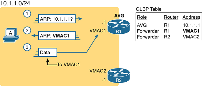
Figure D-10 GLBP Directs Host A by Sending Back ARP Reply with R1’s VMAC1
The figure shows three messages, top to bottom, with the following action:
Host A has no ARP table entry for its default router, 10.1.1.1, so host A sends an ARP Request to learn 10.1.1.1’s MAC address.
The GLBP AVG, R1 in this case, sends back an ARP Reply. The AVG chooses to include its own virtual MAC address in the ARP Reply, VMAC1.
Future IP packets sent by host A are encapsulated in Ethernet frames, destined to VMAC1, so that they arrive at R1.
From now on, host A sends off-subnet packets to R1 due to host A’s ARP table entry for its default gateway (10.1.1.1). Host A’s ARP table entry for 10.1.1.1 now refers to a MAC address on R1 (VMAC1), so packets host A sends off-subnet flow through R1.
To balance the load, the AVG answers each new ARP Request with the MAC addresses of alternating routers. Figure D-11 continues the load-balancing effect with the ARP Request for 10.1.1.1 coming from host B. The router acting as AVG (R1) still sends the ARP Reply, but this time with R2’s virtual MAC (VMAC2).
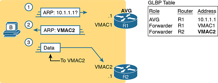
Figure D-11 GLBP Directs Host B by Sending Back ARP Reply with R2’s VMAC2
Here are the steps in the figure:
Host B sends an ARP Request to learn 10.1.1.1’s MAC address.
The GLBP AVG (R1) sends back an ARP Reply, listing VMAC2, R2’s virtual MAC address.
For future packets sent off-subnet, host B encapsulates the packets in Ethernet frames, destined to VMAC2, so that they arrive at R2.
The process shown in Figures D-10 and D-11 balances the traffic, per host, but the routers must also be ready to take over for the other router if it fails. GLBP refers to each router as a forwarder. When all is well, each router acts as forwarder for its own virtual MAC address, but it listens to GLBP messages to make sure the other forwarders are still working. If another forwarder fails, the still-working forwarder takes over the failed forwarder’s virtual MAC address role and continues to forward traffic.
Configuring and Verifying GLBP
GLBP configuration mimics HSRP configuration to a great degree.
Example D-16 shows a GLBP configuration with both routers using GLBP group 1, with virtual IP address 10.1.1.1, with the glbp 1 ip 10.1.1.1 interface subcommand.
Example D-16 GLBP Configuration on R1 and R2, Sharing IP Address 10.1.1.1
! First, the configuration on R1
R1# show running-config
! Lines omitted for brevity
interface GigabitEthernet0/0
 ip address 10.1.1.9 255.255.255.0
 glbp 1 ip 10.1.1.1
 glbp 1 priority 110
 glbp 1 name GLBP-group-for-book
! The following configuration, on R2, is identical except for
! the interface IP address, and the GLBP priority
R2# show running-config
! Lines omitted for brevity
interface GigabitEthernet0/0
 ip address 10.1.1.129 255.255.255.0
 glbp 1 ip 10.1.1.1
 glbp 1 name GLBP-group-for-book
Once configured, the two routers negotiate as to which will be the AVG. As with HSRP, if both come up at the same time, R1 will win, with a priority set to 110 with the glbp 1 priority 110 command versus R2’s default priority of 100. However, if either router comes up before the other, that router goes ahead and takes on the AVG role.
Sifting through the GLBP show command output takes a little more work than with HSRP, in particular because of the added detail in how GLBP works. First, consider the show glbp brief command on Router R1, as shown in Example D-17. (Note that many show glbp commands have the same options as equivalent HSRP show standby commands.)
Example D-17 GLBP Status on R1 with show glbp brief
R1# show glbp brief
Interface   Grp  Fwd  Pri State   Address         Active router   Standby router
Gi0/0       1    -    110 Active  10.1.1.1        local           10.1.1.129
Gi0/0       1    1    -   Listen  0007.b400.0101  10.1.1.129      -
Gi0/0       1    2    -   Active  0007.b400.0102  local
Before looking at the right side of the output, first consider the context for a moment. This example lists a heading line and three rows of data. These data rows are identified by the Grp and Fwd headings, short for Group and Forwarder. With only one GLBP group configured, R1 lists lines only for group 1. More important, each row defines details about a different part of what GLBP does, as follows:
Fwd is -: This line refers to none of the forwarders, and instead describes the AVG.
Fwd is 1: This line describes GLBP forwarder (router) 1.
Fwd is 2: This line describes GLBP forwarder (router) 2.
The output usually lists the line about the AVG first, as noted with a dash in the Forwarder column. Now look at the highlighted portions on the right of Example D-17. This line will list the virtual IP address and identify the active AVG and the standby AVG. This particular command, from Router R1, lists R1 itself (“local”) as the active router. So, R1 is the current AVG.
Each of the next two lines lists status information about one of the forwarder roles; that is, a router that uses a virtual MAC address, receives frames sent to that address, and routes the packets encapsulated in those frames. To that end, the Address column lists MAC addresses, specifically the virtual MAC addresses used by GLBP, and not the interface MAC addresses.
Each forwarder row also identifies the router that currently uses the listed virtual MAC in the Active Router column. In Example D-17, 0007.b400.0101 is used by the router with interface IP address 10.1.1.129 (which happens to be R2). 0007.b400.0102 is supported by the local router (the router on which the show command was issued), which is R1.
The brief output of the show glbp brief command lists many details, but it takes some effort to learn how to sift through it all. For more perspective on the output, Example D-18 lists this same show glbp brief command, this time on R2. Note that the Fwd column again identifies the first line of output as being about the AVG, with the next two lines about the two forwarders.
Example D-18 GLBP Status on R2 with show glbp brief
R2# show glbp brief
Interface   Grp  Fwd Pri State    Address         Active router     Standby router
Gi0/0       1    -   100 Standby  10.1.1.1        10.1.1.9          local
Gi0/0       1    1   -   Active   0007.b400.0101  local             -
Gi0/0       1    2   -   Listen   0007.b400.0102  10.1.1.9          -
The State column in the output in Examples D-17 and D-18 can pull the GLBP concepts together. First, to define the meaning of the state values, the following short list defines the states expected for the first line of output, about the AVG, and then about each GLBP forwarder:
AVG: One router should be the active AVG, with the other acting as standby, ready to take over the AVG role if the AVG fails.
Each forwarder: One router should be active, while the other should be listening, ready to take over that virtual MAC address if that forwarder fails.
Table D-4 collects the values of the State column from Examples D-17 and D-18 for easier reference side by side. Note that, indeed, each line has either an active/standby pair (for the AVG) or an active/listen pair (for the forwarder function).
Table D-4 Comparing Local State in show glbp brief Commands
Row Is About… |
Fwd Column Value |
R1 State |
R2 State |
AVG |
- |
Active |
Standby |
Forwarder 1 |
1 |
Listen |
Active |
Forwarder 2 |
2 |
Active |
Listen |
Finally, the show glbp command lists a more detailed view of the current GLBP status. Example D-19 shows a sample from Router R1. Note that the first half of the output has similar information compared to HSRP’s show standby command, plus it lists the IP and MAC addresses of the routers in the GLBP group. Then, the end of the output lists a group of messages per GLBP forwarder.
Example D-19 GLBP Status on R1 with show glbp
R1# show glbp
GigabitEthernet0/0 - Group 1
  State is Active
    2 state changes, last state change 00:20:59
  Virtual IP address is 10.1.1.1
  Hello time 3 sec, hold time 10 sec
    Next hello sent in 2.112 secs
  Redirect time 600 sec, forwarder timeout 14400 sec
  Preemption disabled
  Active is local
  Standby is 10.1.1.129, priority 100 (expires in 8.256 sec)
  Priority 110 (configured)
  Weighting 100 (default 100), thresholds: lower 1, upper 100
  Load balancing: round-robin
  IP redundancy name is "GLBP-group-for-book"
  Group members:
    0200.0101.0101 (10.1.1.9) local
    0200.0202.0202 (10.1.1.129)
  There are 2 forwarders (1 active)
  Forwarder 1
  State is Listen
    2 state changes, last state change 00:20:34
  MAC address is 0007.b400.0101 (learnt)
  Owner ID is 0200.0202.0202
  Redirection enabled, 598.272 sec remaining (maximum 600 sec)
  Time to live: 14398.272 sec (maximum 14400 sec)
  Preemption enabled, min delay 30 sec
  Active is 10.1.1.129 (primary), weighting 100 (expires in 8.352 sec)
  Client selection count: 1
  Forwarder 2
    State is Active
      1 state change, last state change 00:24:25
  MAC address is 0007.b400.0102 (default)
  Owner ID is 0200.0101.0101
  Redirection enabled
  Preemption enabled, min delay 30 sec
  Active is local, weighting 100
  Client selection count: 1
Implementing Simple Network Management Protocol
This section includes details of how to implement SNMPv2c and SNMPv3.
Implementing SNMP Version 2c
The exam topics mention SNMPv2c and SNMPv3 by name. As it turns out, SNMPv1 and SNMPv2c configuration is very similar, because both use communities. SNMPv3 varies quite a bit, mainly to implement the better SNMPv3 security features. This next section shows how to configure and verify SNMPv2c.
Configuring SNMPv2c Support for Get and Set
SNMP configuration in Cisco IOS routers and switches works a little differently than many other IOS features. First, the SNMP configuration exists in a series of global commands; there is no SNMP agent configuration mode in which to collect subcommands. Secondly, no single command enables the SNMP agent. Instead, IOS typically defaults for the SNMP agent to be disabled. Then, the first time an snmp-server global command is configured, IOS enables the SNMP agent.
With that backdrop, a typical SNMPv2c configuration requires only one or two settings. To be useful, the agent needs at least a read-only (RO) community string. The agent will not reply to SNMPv2c Get messages without at least the RO community string configured. The network engineer may also want the agent to have a read-write (RW) community string, to support Set messages.
The following checklist details the commands used to configure SNMPv2c on a Cisco router or switch. This list shows the method to configure the RO and RW communities, plus a few optional but common settings (location and contact information).
Step 1. Use the snmp-server community communitystring RO [ipv6 acl-name] [acl-name] command in global configuration mode to enable the SNMP agent (if not already started), set the read-only community string, and restrict incoming SNMP messages based on the optional referenced IPv4 or IPv6 ACL.
Step 2. (Optional) Use the snmp-server community communitystring RW [ipv6 acl-name] [acl-name] command in global configuration mode to enable the SNMP agent (if not already started), set the read-write community string, and restrict incoming SNMP messages based on the optional referenced IPv4 or IPv6 ACL.
Step 3. (Optional) If referenced by an snmp-server community command, configure an IPv4 or IPv6 ACL, with the same name or number referenced by the snmp-server community command, with the ACL permitting by matching the source IPv4 or IPv6 address of the allowed SNMP management hosts.
Step 4. (Optional) Use the snmp-server location text-describing-location command in global configuration mode to document the location of the device.
Step 5. (Optional) Use the snmp-server contact contact-name command in global configuration mode to document the person to contact if problems occur.
Example D-20 shows a sample configuration based on Figure D-12. The examples in this section come from Router R1, although the exact same SNMP configuration syntax could be used in the LAN switches or in R2. (The configuration of the location information would likely differ for each device, however.) Note that the configuration creates an IPv4 ACL that permits traffic with source IP address 10.1.3.3, which is the address of the NMS shown in the figure. It then defines read-only and read-write communities, along with the location and contact name for the router.
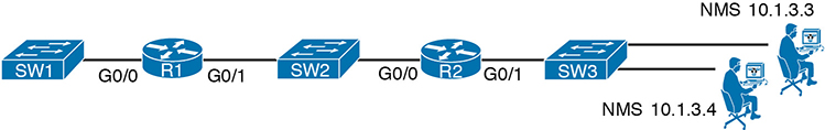
Figure D-12 Sample Network for SNMP Examples, with NMS at 10.1.3.3
Example D-20 Configuring SNMP Version 2c on Router R1 to Support Get and Set
ip access-list standard ACL_PROTECTSNMP
 permit host 10.1.3.3
!
snmp-server community secretROpw RO ACL_PROTECTSNMP
snmp-server community secretRWpw RW ACL_PROTECTSNMP
snmp-server location Atlanta
snmp-server contact Tyler B
To begin managing Router R1 (or any of the other devices that use the same community strings), the SNMP manager at address 10.1.3.3 now needs to configure the community strings listed in Example D-20.
Configuring SNMPv2c Support for Trap and Inform
For an SNMPv2c agent in a router or switch to be able to send unsolicited notifications to an SNMP manager (that is, to send Trap and Inform messages), the device needs to be configured with the snmp-server host command. This command references the NMS to which the Traps or Informs should be sent, along with the SNMP version.
Beyond telling the SNMP agent the hostname or address of the NMS, the agent typically needs to know the notification community string used by the NMS. Think of the RO and RW community strings as protecting the SNMP agent from the messages originated by an NMS (Get or Set Requests), so the agent requires the NMS to supply the correct RO or RW community string. For Traps and Informs, the NMS can protect itself from the Trap and Inform messages originated by SNMP agents by requiring those agents to include the notification community with those messages. The agent can configure this value on the snmp-server host command as well.
The following list details the command to enable the sending of SNMPv2c Trap or Inform messages to an NMS:
Step 1. Use the snmp-server host {hostname | ip-address} [informs] version 2c notification-community command in global configuration mode to configure the SNMP agent to send either SNMPv2c Traps (default) or Informs to the listed host. Use this command once for each host to which this device should send Traps.
Step 2. Use the snmp-server enable traps command in global configuration mode to enable the sending of all supported types of Trap and Inform messages.
Example D-21 shows a sample configuration. In most cases, you would send either Traps or Informs to a particular NMS, but not both. So, for this example, the configuration shows how to configure to send Traps to one host (10.1.3.3), and Informs to another host (10.1.3.4). Note that this configuration is added to Router R1 from Figure D-12, but it could have been added to Router R2 or to any of the LAN switches as well.
Example D-21 Configuring SNMP Version 2c on Router R1 to Support Sending Traps
snmp-server host 10.1.3.3 version 2c secretTRAPpw
snmp-server host 10.1.3.4 informs version 2c secretTRAPpw
snmp-server enable traps
Verifying SNMPv2c Operation
Example D-22 displays some of the status information based on the configuration seen in the previous two examples. The variations on the show snmp command highlight several configuration settings. For example, the show snmp community command repeats the community string values, with reference to any attached IPv4 or IPv6 ACLs. The show snmp host command lists the IP address or hostname of the NMS referenced by each snmp-server host configuration command.
Example D-22 Confirming SNMPv2c Configuration Settings on Router R1
R1# show snmp community

Community name: secretROpw
Community Index: secretROpw
Community SecurityName: secretROpw
storage-type: nonvolatile    active access-list: ACL_PROTECTSNMP

Community name: secretRWpw
Community Index: secretRWpw
Community SecurityName: secretRWpw
storage-type: nonvolatile    active access-list: ACL_PROTECTSNMP

Community name: secretTRAPpw
Community Index: secretTRAPpw
Community SecurityName: secretTRAPpw
storage-type: nonvolatile active

R1# show snmp location
Atlanta

R1# show snmp contact
Tyler B

R1# show snmp host
Notification host: 10.1.3.4     udp-port: 162    type: inform
user: secretTRAPpw      security model: v2c

Notification host: 10.1.3.3     udp-port: 162    type: trap
user: secretTRAPpw      security model: v2c
The show snmp command takes the opposite approach from the commands in Example D-22, focusing almost completely on status and counter information, rather than repeating configuration settings. This command lists dozens of lines of detailed information, so the sample in Example D-23 shows just enough of the output to give you a sense of the kinds of information found there, with comments following the example.
Example D-23 Finding SNMPv2c Message Load on Router R1
R1# show snmp
Chassis: FTX162883H0
Contact: Tyler B
Location: Atlanta
7735 SNMP packets input
    0 Bad SNMP version errors
    9 Unknown community name
    0 Illegal operation for community name supplied
    2 Encoding errors
    51949 Number of requested variables
    2 Number of altered variables
    3740 Get-request PDUs
    3954 Get-next PDUs
    7 Set-request PDUs
    0 Input queue packet drops (Maximum queue size 1000)
7850 SNMP packets output
    0 Too big errors (Maximum packet size 1500)
    0 No such name errors
    0 Bad values errors
    0 General errors
    7263 Response PDUs
    126 Trap PDUs
! Lines omitted for brevity
The output in Example D-23 was taken from Router R1 as shown in the earlier examples, after doing some testing from the NMS at address 10.1.3.3. The highlighted items point out the number of SNMP packets received (input) and sent (output), as well as the number of requested MIB variables—that is, the number of variables requested in different SNMP Get requests. (Note that SNMP also supports the GetNext and GetBulk commands, so a single NMS user click can cause the NMS to Get many variables from an agent; thus, it is not unusual for the requested variables counter to get very large.) The output also shows that seven Set requests were received, resulting in two changes to variables. The fact that two Set requests changed variables is a good fact to know if you are wondering if someone has reconfigured something on the device using SNMP.
Implementing SNMP Version 3
SNMPv3 configuration on Cisco routers and switches has some commands in common with SNMPv2c configuration, and some completely different commands. The configuration to support sending Traps and Informs, using the snmp-server host and snmp-server enable traps commands, works almost identically, with a few small differences. However, SNMPv3 replaces all references to communities, and as a result does not use the snmp-server community command at all. Instead, it uses the snmp-server group and snmp-server user commands to configure the security features available to SNMPv3.
SNMPv3 has many more configuration options, and it is easy to get confused by the details. So, to get started, first look at a short SNMPv3 configuration example, as shown in Example D-24. The example highlights the values you would have to choose, but the values are either text fields (names and passwords) or the IP address of the NMS. This configuration could be used to replace the SNMPv2c configuration and use username/password authentication. The requirements met in the example are
Use SNMPv3 authentication (basically replacing SNMPv2 communities).
Use username Youdda and authentication password madeuppassword (in your network, you would choose your own values).
Do not use SNMPv3 privacy (that is, message encryption).
Allow both read (Get) and write (Set) access.
Send Traps to an NMS (10.1.3.3), authenticating with the same username.
Example D-24 Configuring SNMPv3 on R1—Authentication Only
R1(config)# snmp-server group BookGroup v3 auth write v1default
R1(config)# snmp-server user Youdda BookGroup v3 auth md5 madeuppassword
R1(config)# snmp-server host 10.1.3.3 version 3 auth Youdda
Given the list of requirements, you could probably just read the configuration in Example D-24, compare that to the list of requirements preceding the example, and correctly guess what most of the command parameters mean. However, we need to get into more detail to work through these commands and their options so that you understand the entire configuration, which is exactly what the next few pages do.
SNMPv3 Groups
SNMPv3 authentication uses a username/password combination. When Cisco created its SNMPv3 implementation in IOS, it realized that it might be useful to have groups of users that use some of the same security settings. So, rather than have each snmp-server user command (the command that defines a user) define every single security parameter, Cisco put some of the security configuration settings into the snmp-server group command. This command holds SNMPv3 security settings that are often the same between a group of SNMPv3 users; each snmp-server user command then refers to one SNMP group. This next topic explores those security parameters defined on the snmp-server group command.
Figure D-13 shows the entire snmp-server group command. The required parameters on the left include a name that the network engineer can make up; it only needs to match other commands on the local router. For SNMPv3 configuration, the v3 keyword would always be used. The text following this figure then details the rest of the parameters in the figure.
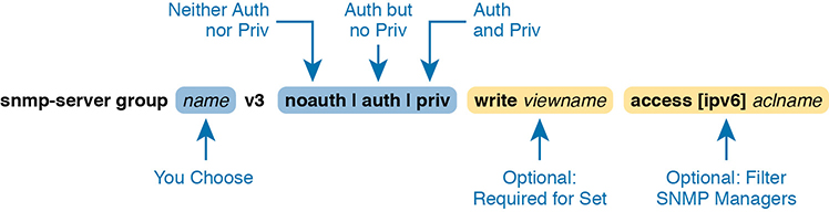
Figure D-13 SNMPv3 Groups—Configuration Command Parameters
The next parameter in the command configures this group of users to use one of three SNMPv3 security levels. As you can see from the summary in Table D-5, all three security levels provide message integrity for their messages, which confirms that the message has not been changed in transit. The auth option adds authentication to message integrity, using a username and password, with IOS storing the password with a hash and never sending the password as clear text. The last increase in security level, configured by using the priv security level, causes the SNMP manager and agent to encrypt the entire SNMP packet for all SNMP messages sent, in addition to performing message integrity and authentication.
Table D-5 SNMPv3 Security Levels Keywords and Their Meanings
Command Keyword |
Keyword in Messages |
Checks Message Integrity? |
Performs Authentication? |
Encrypts Messages? |
noauth |
noAuthNoPriv |
Yes |
No |
No |
auth |
authNoPriv |
Yes |
Yes |
No |
priv |
authPriv |
Yes |
Yes |
Yes |
Continuing to look at the snmp-server group command in Figure D-13, notice that it ends with an optional ACL to filter packets. This same idea is used in SNMPv2c to reference an IPv4 or IPv6 ACL to filter incoming messages coming from the SNMP manager.
So far, the discussion has ignored one part of the snmp-server group command: the idea of SNMPv3 MIB views. MIB views define a subset of the MIB. IOS supplies a series of MIB views for us, and you can define your own MIB views if you like. However, this book discusses only one predefined MIB view that goes by the name v1default, which is a MIB view that includes all the useful parts of the MIB. Instead of focusing on the depths of how you might create different views of a router or switch MIB that has literally thousands of variables, focus on how the snmp-server group command uses that one MIB view that includes the majority of the MIB.
By default, each SNMPv3 group, as defined with the snmp-server group command, has a read MIB view of v1default, and no write view. As a result, the SNMP agent will process received SNMPv3 Get requests, but not process received SNMPv3 Set requests. That complete lack of a write MIB view basically results in read-only behavior for the SNMP agent, as shown at the top of Figure D-14.
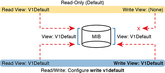
Figure D-14 SNMPv3 Views Creating Read-Only and Read-Write Effect
The bottom of the figure shows the concept behind configuring an SNMP group with the write v1default parameters, causing the group to use the same write view of the MIB that is used for reading the MIB. By including write v1default in the snmp-server group command, you migrate from a default operation of allowing only Gets to now also allowing Sets.
To pull these ideas together, Example D-25 shows four similar SNMPv3 groups, which could later be referenced by snmp-server user commands. Two commands use the parameters write v1default, and two do not, so two groups create read-write (Get and Set) support, and two groups create read-only (Get only) support. Also, note that two groups refer to an IPv4 ACL by name (SNMPACL), and two do not. The ends of the lines in the example list comments about each command.
Example D-25 SNMPv3 Groups—Comparisons with Write Views and ACL Security
ip access-list standard SNMPACL
   permit host 10.1.3.3
!
snmp-server group Group1 v3 noauth                 ! No writes, no ACL
snmp-server group Group2 v3 noauth write v1default ! Allows writes, no ACL
snmp-server group Group3 v3 noauth access SNMPACL  ! No writes, uses ACL
snmp-server group Group4 v3 noauth write v1default access SNMPACL ! Allows writes, uses ACL
Note that while all four examples use an authentication type of noauth, groups could be defined that use the auth and priv types as well. Configuring groups with any one of the security levels does not change the meaning and use of the write and access keywords and their parameters. The security level simply needs to match the security level configured on the snmp-server user commands that refer to the group by name, as seen in the next section.
SNMPv3 Users, Passwords, and Encryption Keys
The snmp-server user command configures other security parameters for the SNMP agent. In particular, it configures
The username
The authentication password and the authentication hash algorithm (MD5 or SHA)
The encryption key and the encryption algorithm (DES, 3DES, AES)
A reference to an snmp-server group command by name, which holds more security configuration
The snmp-server user command still has plenty of moving parts, even with some of the security configuration sitting in the snmp-server group command. Figure D-15 connects these configuration concepts together, showing both commands in one place. Some explanation follows the figure.

Figure D-15 SNMPv3 Users and Groups: Configured
The snmp-server user command creates the username itself. The network engineer can make up a name. The next two parameters must match the chosen snmp-server group command associated with this user, by matching the group name and the v3 keyword (meaning SNMPv3). Any mistakes here will result in this SNMP user not being associated with the SNMP group.
You must pay particular attention to the security type in the associated snmp-server group command, because it dictates what parameters must be configured toward the end of the snmp-server user command. As noted in Figure D-15 with the arrowed lines, the use of the auth keyword in the snmp-server group command requires that you configure authentication parameters for the user in the snmp-server user command: the password and the choice of authentication hash algorithms. If using the priv keyword in the snmp-server group command, the snmp-server user command must define both authentication and privacy parameters as shown in the figure.
Example D-26 shows a series of snmp-server group and matching snmp-server user commands, one after the other, so you can more easily see the parameters. Note that the snmp-server group commands do not include the optional parameters to enable writes (write v1default) or to use an ACL, just to reduce clutter.
Example D-26 SNMPv3 Configuration Samples: Groups and Users
! The group uses noauth, so the user Youdda1 has no auth nor priv keyword
snmp-server group BookGroup1 v3 noauth
snmp-server user Youdda1 BookGroup1 v3

! The next group uses auth, so the next two users use the auth keyword, but not priv
snmp-server group BookGroup2 v3 auth
snmp-server user Youdda2 BookGroup2 v3 auth md5 AuthPass2
snmp-server user Youdda3 BookGroup2 v3 auth sha AuthPass3

! The next group uses priv, so the next users use both the auth and priv keywords.
snmp-server group BookGroup3 v3 priv
snmp-server user Youdda4 BookGroup3 v3 auth md5 AuthPass3 priv des PrivPass4
snmp-server user Youdda5 BookGroup3 v3 auth md5 AuthPass3 priv 3des PrivPass5
snmp-server user Youdda6 BookGroup3 v3 auth sha AuthPass4 priv aes 128 PrivPass6
Note that the example also shows samples of several authentication and encryption options, as listed in Figure D-15.
Verifying SNMPv3
Verifying SNMPv3 operation begins with confirming the details of the SNMPv3 configuration. You can of course find these with the show running-config command, but two commands in particular repeat the configuration settings. Example D-27 shows the output from one of those commands, show snmp user, taken from Router R1 after adding the configuration listed in Example D-26.
Example D-27 Verifying SNMPv3 Configuration Settings
R3# show snmp user
User name: Youdda1
Engine ID: 800000090300D48CB57D8200
storage-type: nonvolatile      active
Authentication Protocol: None
Privacy Protocol: None
Group-name: BookGroup1

User name: Youdda2
Engine ID: 800000090300D48CB57D8200
storage-type: nonvolatile      active
Authentication Protocol: MD5
Privacy Protocol: None
Group-name: BookGroup2

! Skipping Youdda3, Youdda4, and Youdda5 for brevity

User name: Youdda6
Engine ID: 800000090300D48CB57D8200
storage-type: nonvolatile      active
Authentication Protocol: SHA
Privacy Protocol: AES128
Group-name: BookGroup3
In particular, work through the highlighted output for users Youdda1, Youdda2, and Youdda6, as compared to the configuration in Example D-26. All the highlighted entries basically repeat the settings from the configuration.
Example D-28 lists output from the show snmp group command, which also confirms configuration settings from Example D-26. The most challenging thing to find in this output is what is missing, rather than what is there. Note that this command does not list the SNMP usernames that happen to refer to this group. Also, for groups that do not use an ACL, there is no obvious text that states that no ACL is used. Make sure to compare the output for BookGroup1, which uses an ACL, and the output for BookGroup2, which does not use an ACL.
Example D-28 Verifying SNMPv3 Using show snmp group
R3# show snmp group
groupname: BookGroup1                     security model:v3 noauth
contextname: <no context specified>       storage-type: nonvolatile
readview : v1default                      <no writeview specified>
notifyview: <no notifyview specified>
row status: active      access-list: ACL_PROTECTSNMP

groupname: BookGroup2                     security model:v3 auth
contextname: <no context specified>       storage-type: nonvolatile
readview : v1default                      writeview: <no writeview specified>
notifyview: <no notifyview specified>
row status: active
! Lines omitted for brevity
Implementing SNMPv3 Notifications (Traps and Informs)
SNMP agents can use SNMPv3 to send unsolicited notifications—Trap and Inform messages—to SNMP managers. SNMPv2c uses communities, in this case using the SNMPv2c notification community concept. SNMPv3 uses the same security levels just discussed, but as applied to SNMPv3 notifications.
To configure an SNMPv3 agent to send notifications, you add the security level and the username to the snmp-server host command. That configuration links to the same kinds of snmp-server user commands discussed earlier in this section, which in turn link to an snmp-server group command. Figure D-16 shows how the commands connect to each other.
Figure D-16 Connecting SNMPv3 Notification Configuration with User and Group
Example D-29 shows a few samples of configuration notifications that use SNMPv3. The samples rely on the SNMPv3 usernames and groups as defined in Example D-26. Feel free to refer back to that example, and check to make sure that each snmp-server host command in Example D-29 refers to the correct SNMP security level used by each linked snmp-server group command.
Example D-29 Verifying SNMPv3 Configuration Settings
! The group uses noauth, so the user Youdda1 has no auth nor priv keyword
snmp-server enable traps
snmp-server host 10.1.3.3 version 3 noauth Youdda1         ! Traps w/ noauth
snmp-server host 10.1.3.4 informs version 3 auth Youdda2   ! Informs w/ auth
snmp-server host 10.1.3.5 version 3 priv Youdda4           ! Traps w/ priv
As always, the show snmp command lists the counters that show how many messages flow, including the number of Trap and Inform messages sent by the SNMP agent. To verify the configuration of SNMPv3 notification to NMS hosts, use the show snmp host command. Example D-30 shows the results after configuring Example D-29; note that almost all the fields in Example D-30 repeat the configuration parameters from Example D-29.
Example D-30 Verifying SNMPv3 Configuration Settings
R3# show snmp host
Notification host: 10.1.3.4    udp-port: 162   type: inform
user: Youdda2 security model:  v3 auth

Notification host: 10.1.3.3    udp-port: 162   type: trap
user: Youdda1 security model:  v3 noauth

Notification host: 10.1.3.5    udp-port: 162   type: trap
user: Youdda4 security model:  v3 priv
Summarizing SNMPv3 Configuration
SNMPv3 configuration has many parameters to choose from in several commands. As a result, putting the commands into a configuration checklist earlier in this section did not work as well for learning, so the text instead spelled out the pieces little by little. Now that you have seen how to configure the individual pieces, this configuration checklist summarizes all the different SNMPv3 configuration options discussed in this chapter, for easier review.
Step 1. Use the snmp-server group groupname v3 {noauth | auth | priv} [write v1default] [access [ipv6] acl-name] command in global configuration mode to enable the SNMP agent (if not already started), create a named SNMPv3 group of security settings, set the security level, optionally override the default write view with the same view as defaulted for use as the read MIB view (v1default), and optionally restrict incoming SNMP messages based on the optional referenced IPv4 or IPv6 ACL.
Step 2. To configure users whose referenced SNMPv3 group has a security level of noauth, use the snmp-server user username groupname v3 command in global configuration mode, making sure to reference an SNMPv3 group with security level of noauth configured.
Step 3. To configure users whose referenced SNMPv3 group use the security level of auth:
A. Use the snmp-server user username groupname v3 auth md5 password command in global configuration mode to configure the user and authentication password, and to choose to use MD5 as the authentication hash algorithm.
B. Alternatively, use the snmp-server user username groupname v3 auth sha password command in global configuration mode to configure the user and authentication password, and to choose to use SHA as the authentication hash algorithm.
Step 4. To configure users that use the security level of priv, you will add parameters to the end of the snmp-server user command syntax as configured in step 3, as follows:
A. Add the priv des encryption-key parameters in global configuration mode to the end of the snmp-server user command, to enable the use of DES as the encryption algorithm and to set the encryption key.
B. Add the priv 3des encryption-key parameters in global configuration mode to the end of the snmp-server user command, to enable the use of triple DES (3DES) as the encryption algorithm and to set the encryption key.
C. Add the priv aes {128 | 192 | 256} encryption-key parameters in global configuration mode to the end of the snmp-server user command, to enable the use of AES as the encryption algorithm, to set the length of the encryption key in bits, and to set the seed for the encryption key.
Step 5. Enable the SNMP agent to send notification messages (Traps and/or Informs) to an NMS as follows:
A. Use the snmp-server host {hostname | ip-address} [informs | traps] version 3 {noauth | auth | priv} username command in global configuration mode to configure the SNMP agent to send SNMPv3 Traps to the listed host, using the listed username. Use this command once for each host to which this device should send Traps. Include the informs keyword to send Informs; the traps keyword is the default setting. Use the same security level setting as the link SNMPv3 group.
B. Use the snmp-server enable traps command in global configuration mode to enable the sending of all supported notifications to all hosts defined in snmp-server host commands.
Note that if you review this checklist and get lost, make sure to review and study this section again. SNMPv3 configuration uses a lot of different parameters on three different commands, so it is easy to get lost. The checklist is best used for review once you have a good understanding of the commands.
Analyzing LAN Physical Standard Choices
When you look at the design of a network designed by someone else, you can look at all the different types of cabling used, the different types of switch ports, and the Ethernet standards used in each case. Then ask yourself: Why did they choose a particular type of Ethernet link for each link in the network? Asking that question, and investigating the answer, starts to reveal much about building the physical campus LAN.
The IEEE has done an amazing job developing Ethernet standards that give network designers many options. Two themes in particular have helped Ethernet grow over the long term:
The IEEE has developed many additional 802.3 standards for different types of cabling, different cable lengths, and for faster speeds.
All the physical standards rely on the same consistent data-link details, with the same standard frame formats. That means that one Ethernet LAN can use many types of physical links to meet distance, budget, and cabling needs.
For example, think about the access layer of the generic design drawings, but now think about cabling and Ethernet standards. In practice, access layer switches sit in a locked wiring closet somewhere on the same floor as the end user devices. Electricians have installed unshielded twisted-pair (UTP) cabling used at the access layer, running from that wiring closet to each wall plate at each office, cubicle, or any place where an Ethernet device might need to connect to the LAN. The type and quality of the cabling installed between the wiring closet and each Ethernet outlet dictate what Ethernet standards can be supported. Certainly, whoever designed the LAN at the time the cabling was installed thought about what type of cabling was needed to support the types of Ethernet physical standards that were going to be used in that LAN.
Ethernet Standards
Over time, the IEEE has continued to develop and release new Ethernet standards, for new faster speeds and to support new and different cabling types and cable lengths. Figure D-17 shows some insight into Ethernet speed improvements over the years. The early standards up through the early 1990s ran at 10 Mbps, with steadily improving cabling and topologies. Then, with the introduction of Fast Ethernet (100 Mbps) in 1995, the IEEE began ramping up the speeds steadily over the next few decades, continuing even until today.
Figure D-17 Ethernet Standards Timeline
When the IEEE introduces support for a new type of cabling, or a faster speed, they create a new standard as part of 802.3. These new standards have a few letters behind the name. So, when speaking of the standards, sometimes you might refer to the standard name (with letters). For instance, the IEEE standardized Gigabit Ethernet support using inexpensive UTP cabling in standard 802.3ab. However, more often, engineers refer to that same standard as 1000BASE-T or simply Gigabit Ethernet. Table D-6 lists some of the IEEE 802.3 physical layer standards and related names for perspective.
Table D-6 IEEE Physical Layer Standards
Original IEEE Standard |
Shorthand Name |
Informal Names |
Speed |
Typical Cabling |
802.3i |
10BASE-T |
Ethernet |
10 Mbps |
UTP |
802.3u |
100BASE-T |
Fast Ethernet |
100 Mbps |
UTP |
802.3z |
1000BASE-X |
Gigabit Ethernet, GigE |
1000 Mbps (1 Gbps) |
Fiber |
802.3ab |
1000BASE-T |
Gigabit Ethernet, GigE |
1000 Mbps (1 Gbps) |
UTP |
802.3ae |
10GBASE-X |
10 GigE |
10 Gbps |
Fiber |
802.3an |
10GBASE-T |
10 GigE |
10 Gbps |
UTP |
802.3ba |
40GBASE-X |
40 GigE |
40 Gbps |
Fiber |
802.3ba |
100GBASE-X |
100 GigE |
100 Gbps |
Fiber |
Choosing the Right Ethernet Standard for Each Link
When designing an Ethernet LAN, you can and should think about the topology, with an access layer, a distribution layer, and possibly a core layer. But thinking about the topology does not tell you which specific standards to follow for each link. Ultimately, you need to pick which Ethernet standard to use for each link, based on the following kinds of facts about each physical standard:
The speed
The maximum distance allowed between devices when using that standard/cabling
The cost of the cabling and switch hardware
The availability of that type of cabling already installed at your facilities
Consider the three most common types of Ethernet today (10BASE-T, 100BASE-T, and 1000BASE-T). They all have the same 100-meter UTP cable length restriction. They all use UTP cabling. However, not all UTP cabling meets the same quality standard, and as it turns out, the faster the Ethernet standard, the higher the required cable quality category needed to support that standard. As a result, some buildings might have better cabling that supports speeds up through Gigabit Ethernet, whereas some buildings may support only Fast Ethernet.
The Telecommunications Industry Association (TIA; tiaonline.org) defines Ethernet cabling quality standards. Each Ethernet UTP standard lists a TIA cabling quality (called a category) as the minimum category that the standard supports. For example, 10BASE-T allows for Category 3 (CAT3) cabling or better. 100BASE-T requires higher-quality CAT5 cabling, and 1000BASE-T requires even higher-quality CAT5e cabling. (The TIA standards follow a general “higher number is better cabling” in their numbering.) For instance, if an older facility had only CAT5 cabling installed between the wiring closets and each cubicle, the engineers would have to consider upgrading the cabling to fully support Gigabit Ethernet. Table D-7 lists the more common types of Ethernet and their cable types and length limitations.
Table D-7 Ethernet Types, Media, and Segment Lengths (Per IEEE)
Ethernet Type |
Media |
Maximum Segment Length |
10BASE-T |
TIA CAT3 or better, 2 pairs |
100 m (328 feet) |
100BASE-T |
TIA CAT5 UTP or better, 2 pairs |
100 m (328 feet) |
1000BASE-T |
TIA CAT5e UTP or better, 4 pairs |
100 m (328 feet) |
10GBASE-T |
TIA CAT6a UTP or better, 4 pairs |
100 m (328 feet) |
10GBASE-T1 |
TIA CAT6 UTP or better, 4 pairs |
38–55 m (127–180 feet) |
1000BASE-SX |
Multimode fiber |
550 m (1800 feet) |
1000BASE-LX |
Multimode fiber |
550 m (1800 feet) |
1000BASE-LX |
9-micron single-mode fiber |
5 km (3.1 miles) |
1The option for 10GBASE-T with slightly less quality CAT6 cabling, but at shorter distances, is an attempt to support 10Gig Ethernet for some installations with CAT6 installed cabling. |
||
Ethernet defines standards for using fiber optic cables as well. Fiber optic cables include ultrathin strands of glass through which light can pass. To send bits, the switches can alternate between sending brighter and dimmer light to encode 0s and 1s on the cable.
Generally comparing optical cabling versus UTP cabling Ethernet standards, two obvious points stand out. Optical standards allow much longer cabling, while generally costing more for the cable and the switch hardware components. Optical cables experience much less interference from outside sources compared to copper cables, which allows for longer distances.
When considering optical Ethernet links, many standards exist, but with two general categories. Comparing the two, the cheaper options generally support distances into the hundreds of meters, using less expensive light-emitting diodes (LED) to transmit data. Other optical standards support much longer distances into multiple kilometers, using more expensive cabling and using lasers to transmit the data. The trade-off is basic: For a given link, how long does the cable need to run, what standards support that distance, and which is the least expensive to meet that need?
In reality, most engineers remember only the general facts from tables like Table 10-3: 100 meters for UTP, about 500 meters for multimode fiber, and about 5000 meters for some single mode fiber Ethernet standards. When it is time to get serious about designing the details of each link, the engineer must get into the details, calculating the length of each cable based on its path through the building, and so on.
Metro Ethernet
This section discusses virtual circuits in Ethernet WANs.
Ethernet Virtual Circuit Bandwidth Profiles
Before leaving MetroE to move on to MPLS, it helps to consider some ideas about data usage over the WAN links and a whole topic area related to EVC Bandwidth Profiles (BWP).
First, ignoring MetroE for a moment, anyone who has shopped for mobile phone data plans in the 2010s has already thought about data usage with carrier networks. With mobile phones, many carriers offer some kind of tiered pricing: the more data you want to send and receive, the more money you spend per month. Why do they charge more based on usage? The SP spends a lot of capital and a lot of ongoing operational expense to build and operate its network. It seems fair to charge those who use less of the network a little less money, and those who use more a little more money. Simple enough.
Most private WAN services use the same kind of usage-based pricing, and this last MetroE topic discusses some of the terminology and concepts.
The first big idea is this: The access links transmit bits at a set predefined speed based on Ethernet standards. Each Ethernet access link on a MetroE WAN uses a specific Ethernet standard that runs at a specific speed. Those speeds are 10 Mbps, 100 Mbps, 1000 Mbps (that is, 1 Gbps), 10 Gbps, and so on. And while the IEEE has begun adding some new speeds for Ethernet standards, speeds that are not a multiple of 10 versus the next slower speed, the point is this: If a site’s MetroE access link is using an Ethernet standard that is a 100-Mbps standard, then the bits are transmitted at 100 Mbps.
At the same time, the MetroE SP wants to be able to charge customers based on usage, and to be a little more flexible than pricing based on the speed of the access links. These final few pages of the MetroE topics in this chapter show how a MetroE SP can charge for speeds other than the access link speeds.
Charging for the Data (Bandwidth) Used
Think through this scenario. A potential customer looks at a MetroE provider’s pricing. This customer wants an E-Line service between two sites only. They know that they need at least 100 Mbps of capacity (that is, bandwidth) between the sites. But because the service has the word “Ethernet” in it, the potential customer thinks the service is either 10 Mbps, 100 Mbps, 1 Gbps, and so on. So they look up pricing for an E-Line service at those prices, and think:
100 Mbps: Reasonably good price, but we need more capacity
1000 Mbps: More than we want to spend, it’s enough capacity, but probably too much
As it turns out, what this customer really wants is 200 Mbps between the two sites. However, there is no Ethernet standard that runs at 200 Mbps, so there is no way to use access links that run at 200 Mbps. But there is a solution: an E-Line service, with a Bandwidth Profile that defines a 200-Mbps committed information rate (CIR) over the point-to-point EVC between the customer’s two routers. Figure D-18 shows the ideas and terms.

Figure D-18 Example: 200-Mbps CIR Supported by 1-Gbps Access Links
The big ideas are simple, although the methods to control the data are new. The SP, per the contract with the customer, agrees to not only forward Ethernet frames between the two E-Line sites, but commits to a CIR of 200 Mbps. That is, the carrier commits to pass 200 Mbps worth of Ethernet frames over time.
When a customer asks for a new E-Line with a 200-Mbps CIR, they could send lots more data than 200 Mbps. Remember, the literal transmission rate would be 1 Gbps in this example, because the access links are 1-Gbps links. But over time, if all the customers that asked for a 200-Mbps CIR E-Line sent lots more than 200 Mbps worth of data, the SP’s network could become too congested. The SP builds its network to support the traffic it has committed to send, plus some extra for expected overuse, and some extra for growth. But it is too expensive to build a network that allows customers that ask for and pay for 200 Mbps to send at 1 Gbps all the time.
Controlling Overages with Policing and Shaping
To make the idea of fast access links with a slower CIR on the EVCs work, and work well, both the SP and the customer have to cooperate. The tools are two Quality of Service (QoS) tools called policing and shaping.
Historically, in some similar WAN services (like Frame Relay), the SP would actually let you send more data than your CIR, but MetroE networks typically use policing to discard the excess. A policer can watch incoming frames and identify the frames associated with each EVC. It counts the bytes in each frame, and determines a bit rate over time. When the customer has sent more bits than the CIR, the SP discards enough of the currently arriving frames to keep the rate down to the CIR. Figure D-19 shows the location of policing in the same example shown in Figure D-18.
Figure D-19 SP Polices Incoming Traffic to Discard Excess Beyond CIR
Recapping this scenario, the customer decides to ask the MetroE SP for an E-Line. The customer’s routers use a 1-Gbps access link that allows the E-Line to support a 200-Mbps CIR. To protect the SP’s network, the SP now uses ingress policing to monitor the bits/second received over each end of the E-Line’s point-to-point EVC. And the SP discards some incoming frames when the rate gets too high.
Having the SP discard a few frames is actually not that harmful if QoS is implemented correctly, but with MetroE, if the SP is policing as shown in Figure D-19, the customer needs to use the other QoS tool: shaping. Shaping, as implemented on the customer routers, lets the routers slow down. Shaping tells the routers, on the MetroE access link, to send some frames, and then wait; then send more, then wait; and to do that repeatedly. Shaping can be configured for that same rate as the CIR (200 Mbps in this case), so that the SP does not have to discard any traffic.
Summarizing some of these key points:
MetroE uses the concept of an Ethernet Virtual Connection (EVC), tying a committed number of bits/second called the committed information rate (CIR) to the EVC.
The access links need to be fast enough to handle the combined CIRs for all EVCs that cross the link.
For each EVC, the SP commits to forward the bits/second defined as the CIR for that EVC.
To protect its network from being overrun with too much traffic, the SP can use policing, monitoring the incoming traffic rate on each EVC and discarding traffic that goes beyond the CIR.
To prevent too much of its traffic from being discarded by the SP, the customer slows down its rate of sending over the EVC to match that same CIR, using shaping on the customer router.
MPLS VPNs
This section discusses an OSPF design issue that exists when using MPLS VPNs.
OSPF Area Design with MPLS VPN
Now that you know the basics about what happens with routing protocols at the edge of an MPLS network, take a step back and ponder OSPF area design. For all the other WAN services discussed in the book, the WAN service is just one more data link, so the WAN sits inside one area. With MPLS, the MPLS service acts like a bunch of routers. If you use OSPF as the PE-CE routing protocol, some choices must be made about OSPF areas, and about which WAN links are in which area, and where the backbone area can and should be.
MPLS allows for a couple of variations on OSPF area design, but they all use an idea that was added to OSPF for MPLS VPNs, an idea that has come to be known informally as the OSPF super backbone. The idea is an elegant solution that meets OSPF needs and the requirement that the MPLS PEs, when using OSPF, must be in some OSPF area:
The MPLS PEs form a backbone area by the name of a super backbone.
Each PE-CE link can be any area—a non-backbone area or the backbone area.
Although the super backbone supports some functions and logic beyond the scope of this book, for the purposes of getting a basic understanding of OSPF’s use with MPLS, you can think of the super backbone as simply the majority of an enterprise’s OSPF backbone area, but with the option to make the backbone area larger. The CE routers at a customer site may not be part of the backbone area, or may be, at the choice of the customer network engineers.
For example, for a nice clean design, each of the four customer sites in Figure D-20 uses a different area. The PE-CE links are part of those individual areas. The OSPF backbone area still exists, and each area connects to the backbone area, but the backbone exists in the MPLS PE routers only.

Figure D-20 MPLS Design with (Super Backbone) Area 0, Non-Backbone Area for Each Site
The area design in Figure D-20 provides a clean OSPF area design. However, if migrating from some other type of WAN service, with an existing OSPF design, the network engineers may prefer to keep parts of an existing OSPF design, which means some sites may still need to include the backbone area. In fact, multiple WAN sites can be configured to be in the backbone area, and still function correctly. Figure D-21 shows one such example.
Figure D-21 Using Area 0 on CE-PE Link, or for Entire Site
In effect, the super backbone combines with the two other parts of the network configured as area 0 for one contiguous backbone area. Notice on the left side of Figure D-21 the two sites with area 0 noted. Normally, if both customer sites implement area 0, but there were links from some other area between them, the design would break OSPF design rules. However, the OSPF backbone (area 0) links on the left, plus the OSPF super backbone area 0 created by MPLS, act together in regard to OSPF design.
Next, focus on the site at the upper left. That site represents what might have existed before migrating to an MPLS design, with Router R1’s links in area 0, and the links connected to Routers R2 and R3 in area 1. The enterprise network engineer may have decided to leave the OSPF area design alone when connecting to the MPLS network. To support those backbone area links off Router R1, the engineer put the CE1-PE1 link into area 0. As a result, the combined customer area 0 instances and the super backbone area 0 creates one contiguous backbone area.