Chapter 22. Enterprise Network Architecture
This chapter covers the following subjects:
Hierarchical LAN Design Model: This section describes the hierarchical network design, which improves performance, simplifies design, increases scalability, and reduces troubleshooting time.
Enterprise Network Architecture Options: This section describes the different options available for deploying an enterprise campus architecture based on the hierarchical LAN design model.
Enterprise campus networks provide access to network services and resources to end users and endpoints spread over a single geographic location. Campus networks typically support many different kinds of endpoint connectivity for workers and guest users, such as laptops, PCs, mobile phones, IP phones, printers, and video conferencing systems.
A small campus network environment might span a single floor or a single building, while a larger campus network might span a large group of buildings spread over an extended geographic area. Large campus networks must have a core or backbone for interconnectivity to other networks, such as the campus end-user/endpoint access, the data center, the private cloud, the public cloud, the WAN, and the Internet edge. The largest enterprises might have multiple campus networks distributed worldwide, each providing both end-user access and core network connectivity.
An enterprise campus architecture is designed to meet the needs of organizations that range from a small single building or remote site to a large, multi-building location.
This chapter provides a high-level overview of the enterprise campus architectures that can be used to scale from a small environment (with just a few LAN switches) to a large campus size network.
“Do I Know This Already?” Quiz
The “Do I Know This Already?” quiz allows you to assess whether you should read the entire chapter. If you miss no more than one of these self-assessment questions, you might want to move ahead to the “Exam Preparation Tasks” section. Table 22-1 lists the major headings in this chapter and the “Do I Know This Already?” quiz questions covering the material in those headings so you can assess your knowledge of these specific areas. The answers to the “Do I Know This Already?” quiz appear in Appendix A, “Answers to the ‘Do I Know This Already?’ Quiz Questions.”
Table 22-1 “Do I Know This Already?” Foundation Topics Section-to-Question Mapping
Foundation Topics Section |
Questions |
Hierarchical LAN Design Model |
1–3 |
Enterprise Network Architecture Options |
4–6 |
1. Which of the following best describe the hierarchical LAN design model? (Choose all that apply.)
It allows for easier troubleshooting.
It is highly scalable.
It provides a simplified design.
It offers improved performance.
It is the best design for modern data centers.
It allows for faster problem isolation.
2. The access layer is also commonly referred to as the _____.
endpoint layer
aggregation layer
end-user layer
network edge
3. What is the maximum number of distribution switches that can be deployed within a hierarchical LAN design building block?
Four
Two
Six
No limit
4. Which of the following enterprise network architectures is also known as the collapsed core?
Three-tier design
Simplified campus design
Two-tier design
Leaf–spine design
5. Which network blocks can provide access to cloud providers for end users? (Choose two.)
WAN edge
Internet edge
Network services edge
Data center
6. Which technologies are used to deploy a simplified campus design? (Choose all that apply.)
Clustering technologies
Stacking technologies
Virtual switching systems (VSSs)
StackWise
Daisy-chaining
Answers to the “Do I Know This Already?” quiz:
1 A, B, C, D, F
2 D
3 B
4 C
5 A, B
6 A, B, C, D
Foundation Topics
Hierarchical LAN Design Model
A hierarchical LAN design model divides the enterprise network architecture into modular layers. By breaking up the design into modular layers, you can have each layer to implement specific functions. These modular layers can be easily replicated throughout the network, which simplifies the network design and provides an easy way to scale the network as well as a consistent deployment method.
A hierarchical LAN design avoids the need for a flat and fully meshed network in which all nodes are interconnected. In fully meshed network architectures, network changes tend to affect a large number of systems. Hierarchical design provides fault containment by constraining the network changes to a subset of the network, which affects fewer systems and makes it easy to manage as well as improve resiliency. In a modular layer design, network components can be placed or taken out of service with little or no impact to the rest of the network; this facilitates troubleshooting, problem isolation, and network management.
The hierarchical LAN design divides networks or their modular blocks into the following three layers:
Access layer: Gives endpoints and users direct access to the network.
Distribution layer: Provides an aggregation point for the access layer and acts as a services and control boundary between the access layer and the core layer.
Core layer (also referred to as the backbone): Provides connections between distribution layers for large environments.
Figure 22-1 illustrates a hierarchical LAN design using the three layers.

Figure 22-1 Hierarchical LAN Design
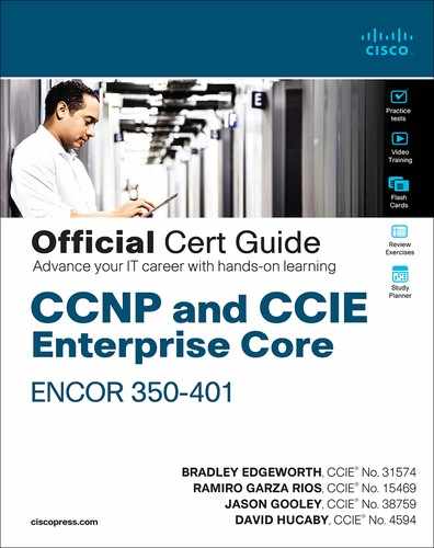
Each layer provides different functionalities and capabilities to the network. The number of layers needed depends on the characteristics of the network deployment site. As illustrated in Figure 22-2, a small campus in a single building might require only access and distribution layers, while a campus that spans multiple buildings will most likely require all three layers. Regardless of how many layers are implemented at a geographic location, the modularity of this design ensures that each layer will provide the same services and the same design methods.
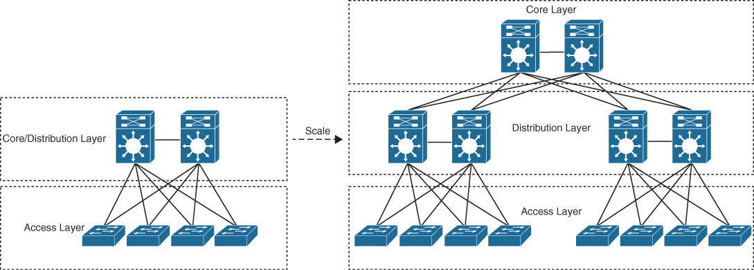
Figure 22-2 Modular Design Scalability
Access Layer
The access layer, also commonly referred as the network edge, is where end-user devices or endpoints connect to the network. It provides high-bandwidth device connectivity using wired and wireless access technologies such as Gigabit Ethernet and 802.11n and 802.11ac wireless. While endpoints in most cases will not use the full capacity of these connections for extended periods of time, the ability to burst up to these high bandwidths when required helps improve the quality of experience (QoE) and productivity of the end user.
Figure 22-3 illustrates the different types of endpoints that connect to the access layer, such as personal computers (PCs), IP phones, printers, wireless access points, personal telepresence devices, and IP video surveillance cameras. Wireless access points and IP phones are prime examples of devices that can be used to extend the access layer one more layer out from the access switch.

Figure 22-3 Access Layer Connectivity
The access layer can be segmented (for example, by using VLANs) so that different devices can be placed into different logical networks for performance, management, and security reasons. In the hierarchical LAN design, the access layer switches are not interconnected to each other. Communication between endpoints on different access layer switches occurs through the distribution layer.
Because the access layer is the connection point for endpoints, it plays a big role in ensuring that the network is protected from malicious attacks. This protection includes making sure the end users and endpoints connecting to the network are prevented from accessing services for which they are not authorized. Furthermore, the quality of service (QoS) trust boundary and QoS mechanisms are typically enabled on this layer to ensure that QoS is provided end-to-end to satisfy the end user’s QoE.
Distribution Layer
The primary function of the distribution layer is to aggregate access layer switches in a given building or campus. The distribution layer provides a boundary between the Layer 2 domain of the access layer and the core’s Layer 3 domain. This boundary provides two key functions for the LAN: On the Layer 2 side, the distribution layer creates a boundary for Spanning Tree Protocol (STP), limiting propagation of Layer 2 faults, and on the Layer 3 side, the distribution layer provides a logical point to summarize IP routing information when it enters the core of the network. The summarization reduces IP routing tables for easier troubleshooting and reduces protocol overhead for faster recovery from failures.
Figure 22-4 illustrates the distribution layer. The distribution switches need to be deployed in pairs for redundancy. The distribution layer switch pairs should be interconnected to each other using either a Layer 2 or Layer 3 link.
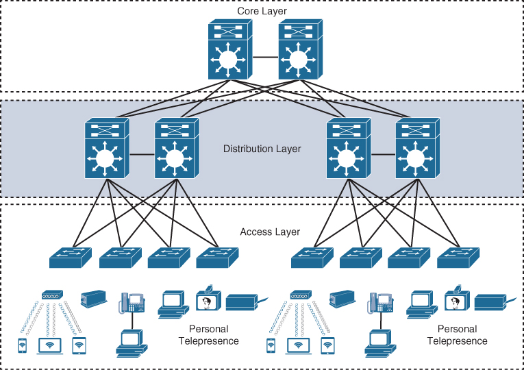
Figure 22-4 Distribution Layer Connectivity
In a large campus environment, multiple distribution layer switches are often required when access layer switches are located in multiple geographically dispersed buildings to reduce the number of fiber-optic runs (which are costly) between buildings. Distribution layer switches can be located in various buildings as illustrated in Figure 22-5.
Figure 22-5 Distribution Layer Reducing Fiber-Optic Runs
Core Layer
As networks grow beyond three distribution layers in a single location, organizations should consider using a core layer to optimize the design. The core layer is the backbone and aggregation point for multiple networks and provides scalability, high availability, and fast convergence to the network.
The core can provide high-speed connectivity for large enterprises with multiple campus networks distributed worldwide, and it can also provide interconnectivity between the end-user/endpoint campus access layer and other network blocks, such as the data center, the private cloud, the public cloud, the WAN, the Internet edge, and network services, as discussed later in this chapter.
The core layer reduces the network complexity, from N × (N − 1) to N links for N distributions, as shown in Figure 22-6.
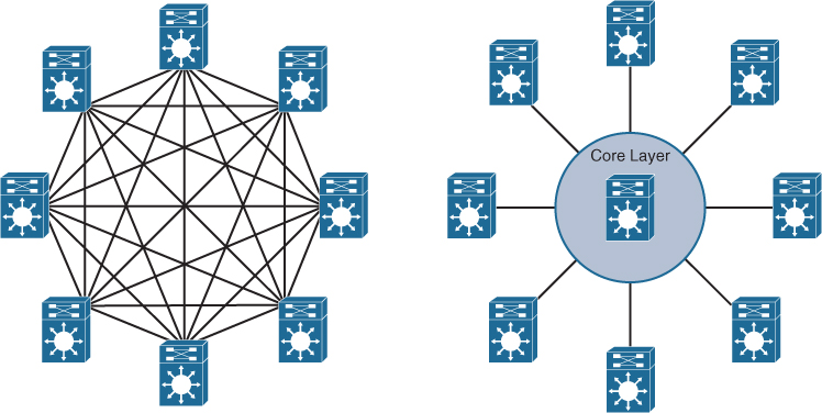
Figure 22-6 Core Layer Reduces Large Network Complexity
Enterprise Network Architecture Options
There are multiple enterprise network architecture design options available for deploying a campus network, depending on the size of the campus as well as the reliability, resiliency, availability, performance, security, and scalability required for it. Each possible option should be evaluated against business requirements. Since campus networks are modular, an enterprise network could have a mixture of all of these options deployed:
Two-tier design (collapsed core)
Three-tier design
Layer 2 access layer (STP based)
Layer 3 access layer (routed access)
Simplified campus design
Software-Defined Access (SD-Access)
Two-Tier Design (Collapsed Core)
Smaller campus networks may have multiple departments spread across multiple floors within a building. In these environments, a core layer may not be needed, and collapsing the core function into the distribution layer can be a cost-effective solution (as no core layer means no core layer devices) that requires no sacrifice of most of the benefits of the three-tier hierarchical model. Prior to selecting a two-tier collapsed core and distribution layers, future scale, expansion, and manageability factors need to be considered.
Figure 22-7 illustrates the two-tier design with the distribution layer acting as a collapsed core.
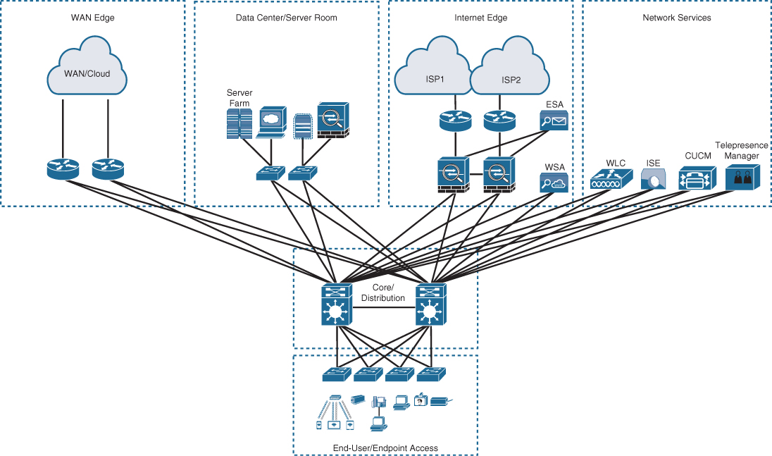
Figure 22-7 Two-Tier/Collapsed Core Design
In Figure 22-7, the distribution/core layer provides connectivity to the WAN edge block, the Internet edge block, the network services block, and so on, and the same pair of core/distribution switches also provides LAN aggregation to the end-user access layer.
The WAN edge block is used to connect to remote data centers, remote branches, or other campus networks or for cloud connectivity to cloud providers such as the “big three” cloud service providers (Amazon Web Services, Microsoft Azure, and Google Cloud Platform) using dedicated interconnections.
The data center/server room block is where business-critical servers are placed to serve up websites, corporate email, business applications, storage, big data processing, backup services, e-commerce transactions, and so on.
The Internet edge block is used for regular Internet access, e-commerce, connection to remote branches, remote VPN access, and cloud provider connectivity that does not require dedicated interconnections.
The network services edge is where devices providing network services reside, such as the wireless LAN controllers (WLCs), Cisco Identity Services Engine (ISE), Cisco TelePresence Manager, and Cisco Unified Communications Manager (CUCM).
Three-Tier Design
Three-tier designs separate the core and distribution layers and are recommended when more than two pairs of distribution switches are required. Multiple pairs of distribution switches are typically required for the following reasons:
When implementing a network for a large enterprise campus composed of multiple buildings, where each building requires a dedicated distribution layer
When the density of WAN routers, Internet edge devices, data center servers, and network services are growing to the point where they can affect network performance and throughput
When geographic dispersion of the LAN access switches across many buildings in a larger campus facility would require more fiber-optic interconnects back to a single collapsed core
When multiple distribution layers need to be interconnected, it becomes necessary to use a core layer, as illustrated in Figure 22-8.
In Figure 22-8, the building blocks or places in the network (PINs) are each using the hierarchical design model, where each is deployed with a pair of distribution switches connected to the core block. The data center block is an exception because it is using the newer leaf–spine design, which is the new alternative to the three-tier design for modern data centers that have predominantly east–west traffic patterns between servers within the data center. The hierarchical LAN design is more appropriate for north–south traffic flows, such as endpoints communicating with the WAN edge, data center, Internet, or network services blocks.
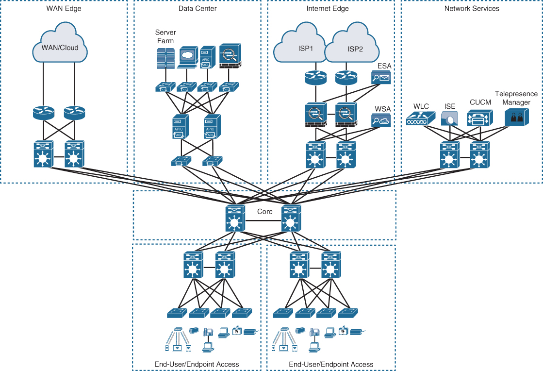
Figure 22-8 Three-Tier Design
Layer 2 Access Layer (STP Based)
Traditional LAN designs use a Layer 2 access layer and a Layer 3 distribution layer. The distribution layer is the Layer 3 IP gateway for access layer hosts. Whenever possible, it is recommended to restrict a VLAN to a single access layer switch to eliminate topology loops, which are common points of failure in LANs, even when STP is enabled in the network. Restricting a VLAN to a single switch provides a loop-free design, but at the cost of network flexibility because all hosts within a VLAN are restricted to a single access switch. Some organizations require that the same Layer 2 VLAN be extended to multiple access layer switches to accommodate an application or a service. The looped design causes STP to block links, which reduces the bandwidth from the rest of the network and can cause slower network convergence.
Figure 22-9 illustrates a loop-free topology where a VLAN is constrained to a single switch as well as a looped topology where a VLAN spans multiple access switches.

Figure 22-9 Loop-Free Topology and Looped Topology
To create a highly available IP gateway at the distribution layer, the distribution layer should have a pair of standalone switches configured with first-hop redundancy protocols (FHRPs) to provide hosts with a consistent MAC address and gateway IP address for each configured VLAN. Hot Standby Router Protocol (HSRP) and Virtual Router Redundancy Protocol (VRRP) are the most common first-hop redundancy protocols; a downside to these protocols is that they only allow hosts to send data out to the active first-hop redundancy protocol router through a single access uplink, which leaves one of the access layer-to-distribution layer uplinks unutilized. Manual configuration of the distribution layer is necessary to be able to load balance VLAN traffic across uplinks; this configuration involves making one of the distribution switches active for odd VLANs and the other active for even VLANs. Gateway Load Balancing Protocol (GLBP) provides greater uplink utilization for access layer-to-distribution layer traffic by load balancing the load from hosts across multiple uplinks; the downside is that it works only on loop-free topologies.
All these redundancy protocols require fine-tuning the default settings in order to allow for sub-second network convergence, which can impact switch CPU resources.
Layer 3 Access Layer (Routed Access)
Routed access is an alternative configuration in which Layer 3 is extended all the way to the access layer switches. In this design, access layer switches act as full Layer 3 routed nodes (providing both Layer 2 and Layer 3 switching), and the access-to-distribution Layer 2 uplink trunks are replaced with Layer 3 point-to-point routed links. Consequently, the Layer 2/Layer 3 demarcation point is moved from the distribution switch to the access switch, as illustrated in Figure 22-10.
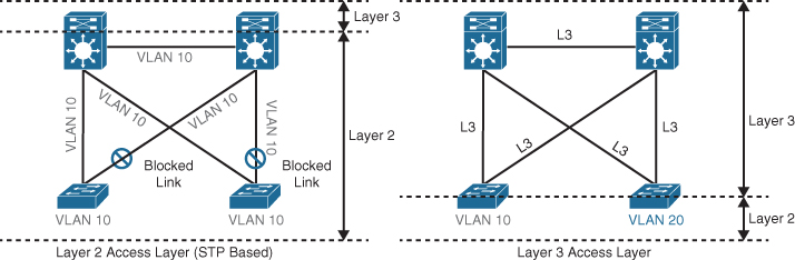
Figure 22-10 Layer 2 Access Layer and Layer 3 Access Layer
The routed access-to-distribution block design has a number of advantages over the Layer 2 access layer design:
No first-hop redundancy protocol required: It eliminates the need for first-hop redundancy protocols such as HSRP and VRRP.
No STP required: Because there are no Layer 2 links to block, this design eliminates the need for STP.
Increased uplink utilization: Both uplinks from access to distribution can be used, increasing the effective bandwidth available to the end users and endpoints connected to the access layer switches.
Easier troubleshooting: It offers common end-to-end troubleshooting tools (such as ping and traceroute).
Faster convergence: It uses fast-converging routing protocols such as Enhanced Interior Gateway Routing Protocol (EIGRP) and Open Shortest Path First (OSPF).
While this is an excellent design for many environments, it has the same limitation as the Layer 2 access loop-free design: It does not support spanning VLANs across multiple access switches. In addition, it might not be the most cost-effective solution because access layer switches with Layer 3 routing capability might cost more than Layer 2 switches.
Simplified Campus Design
The simplified campus design relies on switch clustering such as a virtual switching system (VSS) and stacking technologies such as StackWise, in which multiple physical switches act as a single logical switch. Clustering and stacking technologies can be applied to any of the campus building blocks to simplify them even further. Using this design offers the following advantages:
Simplified design: By using the single logical distribution layer design, there are fewer boxes to manage, which reduces the amount of time spent on ongoing provisioning and maintenance.
No first-hop redundancy protocol required: It eliminates the need for first-hop redundancy protocols such as HSRP and VRRP because the default IP gateway is on a single logical interface.
Reduced STP dependence: Because EtherChannel is used, it eliminates the need for STP for a Layer 2 access design; however, STP is still required as a failsafe in case multiple access switches are interconnected.
Increased uplink utilization: With EtherChannel, all uplinks from access to distribution can be used, increasing the effective bandwidth available to the end users and endpoints connected to the access layer switches.
Easier troubleshooting: The topology of the network from the distribution layer to the access layer is logically a hub-and-spoke topology, which reduces the complexity of the design and troubleshooting.
Faster convergence: With EtherChannel, all links are in forwarding state, and this significantly optimizes the convergence time following a node or link failure event because EtherChannel provides fast sub-second failover between links in an uplink bundle.
Distributed VLANs: With this design, VLANs can span multiple access switches without the need to block any links.
The simplified campus design is loop free, highly available, flexible, resilient, and easy to manage. Figure 22-11 illustrates how the network can be simplified by introducing VSS and StackWise into the design.

Figure 22-11 Simplified Campus Design with VSS and StackWise
In addition, using this design approach across all the campus blocks (when possible) can provide an optimized architecture that is easy to manage, resilient, and more flexible, with higher aggregated uplink bandwidth capacity. Figure 22-12 illustrates what the end-to-end campus would look like with a virtual switching system (VSS) and StackWise used across the different building blocks and layers.
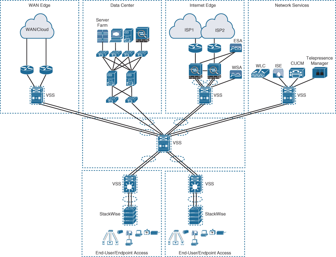
Figure 22-12 Applying VSS and StackWise in a Campus Network
Software-Defined Access (SD-Access) Design
SD-Access, the industry’s first intent-based networking solution for the enterprise, is built on the principles of the Cisco Digital Network Architecture (DNA). It is a combination of the campus fabric design and the Digital Network Architecture Center (Cisco DNA or DNAC). SD-Access adds fabric capabilities to the enterprise network through automation using SD-Access technology, and it provides automated end-to-end segmentation to separate user, device, and application traffic without requiring a network redesign. With its fabric capabilities, SD-Access provides services such as host mobility and enhanced security in addition to the normal switching and routing capabilities. SD-Access is covered in detail in Chapter 23, “Fabric Technologies.”
Exam Preparation Tasks
As mentioned in the section “How to Use This Book” in the Introduction, you have a couple of choices for exam preparation: the exercises here, Chapter 30, “Final Preparation,” and the exam simulation questions in the Pearson Test Prep Software Online.
Review All Key Topics
Review the most important topics in the chapter, noted with the key topics icon in the outer margin of the page. Table 22-2 lists these key topics and the page number on which each is found.
Table 22-2 Key Topics for Chapter 22
Key Topic Element |
Description |
Page |
Section |
Hierarchical LAN design model |
|
List |
Hierarchical LAN design layers |
|
Section |
Access layer |
|
Section |
Distribution layer |
|
Section |
Core layer |
|
Section |
Two-tier design (collapsed core) |
|
Section |
Three-tier design |
|
Section |
Layer 2 access layer (STP based) |
|
Section |
Layer 3 access layer (routed access) |
|
Section |
Simplified campus design |
Complete Tables and Lists from Memory
Print a copy of Appendix B, “Memory Tables” (found on the companion website), or at least the section for this chapter, and complete the tables and lists from memory. Appendix C, “Memory Tables Answer Key,” also on the companion website, includes completed tables and lists you can use to check your work.
Define Key Terms
Define the following key terms from this chapter and check your answers in the Glossary: