Chapter 23. Fabric Technologies
This chapter covers the following subjects:
Software-Defined Access (SD-Access): This section defines the benefits of SD-Access over traditional campus networks as well as the components and features of the Cisco SD-Access solution, including the nodes, fabric control plane, and data plane.
Software-Defined WAN (SD-WAN): This section defines the benefits of SD-WAN over traditional WANs as well as the components and features of the Cisco SD-WAN solution, including the orchestration plane, management plane, control plane, and data plane.
A fabric network is an overlay network (virtual network) built over an underlay network (physical network) using overlay tunneling technologies such as VXLAN. Fabric networks overcome shortcomings of traditional physical networks by enabling host mobility, network automation, network virtualization, and segmentation, and they are more manageable, flexible, secure (by means of encryption), and scalable than traditional networks. This chapter explores the following next-generation overlay fabric technologies:
Software-Defined Access (SD-Access) for campus networks
Software-Defined WAN (SD-WAN) for WAN networks
The Cisco SD-Access fabric is one of the main components of the Cisco Digital Network Architecture (Cisco DNA). Cisco DNA is the solution for the future of intent-based networking in Cisco enterprise networks. SD-Access provides policy-based network segmentation, host mobility for wired and wireless hosts, and enhanced security as well as other benefits in a fully automated fashion. Cisco SD-Access was designed for enterprise campus and branch network environments and not for other types of network environments, such as data center, service provider, and WAN environments.
Traditional WANs are typically designed using MPLS or other overlay solutions, such as Dynamic Multipoint Virtual Private Network (DMVPN) or Intelligent WAN (IWAN) to provide connectivity between different campus and branch sites. However, with the rise of software as a service (SaaS) cloud applications such as Microsoft Office 365 and Salesforce.com, and public infrastructure as a service (IaaS) cloud services from Amazon Web Services (AWS), Google Compute Engine (GCE), and Microsoft Azure, traffic patterns are changing so that the majority of enterprise traffic flows to public clouds and the Internet. Such changes are creating new requirements for security, application performance, cloud connectivity, WAN management, and operations that traditional WAN solutions were not designed to address. The Cisco SD-WAN fabric is a cloud-based WAN solution for enterprise and data center networks that was developed to address all the new WAN requirements.
This chapter defines the components, features, and functions of the Cisco SD-Access and Cisco SD-WAN solutions. Prior to reviewing this chapter, it is highly recommended to review Chapter 16, “Overlay Tunnels,” and Chapter 25, “Secure Network Access Control.” Chapter 16 describes overlay tunneling technologies such as IPsec, VXLAN, and LISP, and Chapter 25 describes Cisco TrustSec. Knowledge of these technologies is essential to understanding many of the concepts described in this chapter.
“Do I Know This Already?” Quiz
The “Do I Know This Already?” quiz allows you to assess whether you should read the entire chapter. If you miss no more than one of these self-assessment questions, you might want to move ahead to the “Exam Preparation Tasks” section. Table 23-1 lists the major headings in this chapter and the “Do I Know This Already?” quiz questions covering the material in those headings so you can assess your knowledge of these specific areas. The answers to the “Do I Know This Already?” quiz appear in Appendix A, “Answers to the ‘Do I Know This Already?’ Quiz Questions.”
Table 23-1 “Do I Know This Already?” Foundation Topics Section-to-Question Mapping
Foundation Topics Section |
Questions |
Software-Defined Access (SD-Access) |
1–6 |
Software-Defined WAN (SD-WAN) |
7–11 |
1. What is the main reason SD-Access uses VXLAN data encapsulation instead of LISP data encapsulation?
VXLAN supports IPv6.
VXLAN supports Layer 2 networks.
VXLAN has a much smaller header.
VXLAN has a better ring to it.
2. True or false: The VXLAN header used for SD-Access is exactly the same as the original VXLAN header.
True
False
3. Which is the control plane used by SD-Access?
LISP control plane
EVPN MP-BGP
Multicast
VXLAN control plane
4. Which field was added to the VXLAN header to allow it to carry SGT tags?
Group Policy ID
Scalable Group ID
Group Based Tag
Group Based Policy
5. Which types of network environments was SD-Access designed for?
Data center
Internet
Enterprise campus and branch
Service provider
WAN
Private cloud
6. Which of the following components are part of the SD-Access fabric architecture? (Choose all that apply.)
WLCs
Cisco routers
Cisco firewalls
Cisco switches
Access points
Cisco ISE
Cisco DNA Center
Intrusion prevention systems
7. What are the main components of the Cisco SD-WAN solution? (Choose four.)
vManage network management system (NMS)
vSmart controller
SD-WAN routers
vBond orchestrator
vAnalytics
Cisco ISE
Cisco DNA Center
8. True or false: The vSmart controller establishes permanent and IPsec connections to all SD-WAN routers in the SD-WAN fabric.
True
False
9. True or false: SD-WAN only works over the Internet or MPLS networks.
True
False
10. Which of the following is the single pane of glass for the SD-WAN solution?
DNA Center
vBond
vManage
vSmart
11. What is the main function of the vBond orchestrator?
To authenticate the vManage NMS and the SD-WAN routers and orchestrate connectivity between them
To authenticate the vSmart controllers and the SD-WAN routers and orchestrate connectivity between them
To authenticate the vSmart controllers and the vManage NMS and orchestrate connectivity between them
Answers to the “Do I Know This Already?” quiz:
1 B
2 B
3 A
4 A
5 C
6 A, B, D, E, F, G
7 A, B, C, D
8 B
9 B
10 C
11 B
Foundation Topics
Software-Defined Access (SD-Access)
There are many operational challenges in enterprise campus networks due to manual configuration of network devices. Manual network configuration changes are slow and lead to misconfigurations that cause service disruptions on the network, and the situation is exacerbated in a constantly changing environment where more users, endpoints, and applications are constantly being added. The constant growth in users and endpoints makes configuring user credentials and maintaining a consistent policy across the network very complex. If policies are inconsistent, there is an added complexity involved in maintaining separate policies between wired and wireless networks that leaves the network vulnerable to security breaches. As users move around the campus network, locating the users and troubleshooting issues also become more difficult. In other words, traditional campus networks do not address the existing campus network needs.
With SD-Access, an evolved campus network can be built that addresses the needs of existing campus networks by leveraging the following capabilities, features, and functionalities:
Network automation: SD-Access replaces manual network device configurations with network device management through a single point of automation, orchestration, and management of network functions through the use of Cisco DNA Center. This simplifies network design and provisioning and allows for very fast, lower-risk deployment of network devices and services using best-practice configurations.
Network assurance and analytics: SD-Access enables proactive prediction of network-related and security-related risks by using telemetry to improve the performance of the network, endpoints, and applications, including encrypted traffic.
Host mobility: SD-Access provides host mobility for both wired and wireless clients.
Identity services: Cisco Identity Services Engine (ISE) identifies users and devices connecting to the network and provides the contextual information required for users and devices to implement security policies for network access control and network segmentation.
Policy enforcement: Traditional access control lists (ACLs) can be difficult to deploy, maintain, and scale because they rely on IP addresses and subnets. Creating access and application policies based on group-based policies using Security Group Access Control Lists (SGACLs) provides a much simpler and more scalable form of policy enforcement based on identity instead of an IP address.
Secure segmentation: With SD-Access it is easier to segment the network to support guest, corporate, facilities, and IoT-enabled infrastructure.
Network virtualization: SD-Access makes it possible to leverage a single physical infrastructure to support multiple virtual routing and forwarding (VRF) instances, referred to as virtual networks (VNs), each with a distinct set of access policies.
What Is SD-Access?
SD-Access has two main components:
Cisco Campus fabric solution
Cisco DNA Center
The campus fabric is a Cisco-validated fabric overlay solution that includes all of the features and protocols (control plane, data plane, management plane, and policy plane) to operate the network infrastructure. When the campus fabric solution is managed using the command-line interface (CLI) or an application programming interface (API) using Network Configuration Protocol (NETCONF)/YANG, the solution is considered to be a campus fabric solution. When the campus fabric solution is managed via the Cisco DNA Center, the solution is considered to be SD-Access, as illustrated in Figure 23-1.
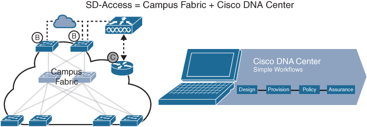
Figure 23-1 SD-Access Solution
SD-Access Architecture
Cisco SD-Access is based on existing hardware and software technologies. What makes Cisco SD-Access special is how these technologies are integrated and managed together. The Cisco SD-Access fabric architecture can be divided into four basic layers, as illustrated in Figure 23-2. The following sections focus on the relationships between these four layers.

Figure 23-2 Cisco SD-Access Architecture
Physical Layer
While Cisco SD-Access is designed for user simplicity, abstraction, and virtual environments, everything runs on top of physical network devices—namely switches, routers, servers, wireless LAN controllers (WLCs), and wireless access points (APs). All Cisco network devices that actively participate in the SD-Access fabric must support all of the hardware Application-Specific Integrated Circuits (ASICs) and Field-Programmable Gate Arrays (FPGAs) and software requirements described in the “Network Layer” section later in this chapter. Cisco access layer switches that do not actively participate in the SD-Access fabric but that are part of it because of automation are referred to as SD-Access extension nodes. The following are the physical layer devices of the SD-WAN fabric:
Cisco switches: Switches provide wired (LAN) access to the fabric. Multiple types of Cisco Catalyst switches are supported, as well as Nexus switches.
Cisco routers: Routers provide WAN and branch access to the fabric. Multiple types of Cisco ASR 1000, ISR, and CSR routers, including the CSRv and ISRv cloud routers, are supported.
Cisco wireless: Cisco WLCs and APs provide wireless (WLAN) access to the fabric.
Cisco controller appliances: Cisco DNA Center and Cisco ISE are the two controller appliances required.
Network Layer
The network layer consists of the underlay network and the overlay network. These two sublayers work together to deliver data packets to and from the network devices participating in SD-Access. All this network layer information is made available to the controller layer.
The network underlay is the underlying physical layer, and its sole purpose is to transport data packets between network devices for the SD-Access fabric overlay.
The overlay network is a virtual (tunneled) network that virtually interconnects all of the network devices forming a fabric of interconnected nodes. It abstracts the inherent complexities and limitations of the underlay network.
Figure 23-3 shows a visual representation of the relationship between an overlay network and the network underlay.
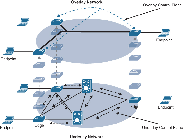
Figure 23-3 Underlay and Overlay Networks
Underlay Network
The underlay network for SD-Access should be configured to ensure performance, scalability, and high availability because any problems with the underlay can affect the operation of the fabric overlay. While it is possible to use a Layer 2 network underlay design running Spanning Tree Protocol (STP), it is not recommended. The recommended design for the network underlay is to use a Layer 3 routed access campus design using IS-IS as the IGP. IS-IS offers operational advantages such as neighbor establishment without IP dependencies, peering capability using loopback addresses, and agnostic treatment of IPv4, IPv6, and non-IP traffic.
Two models of underlay are supported:
Manual underlay: This type of underlay network is configured and managed manually (such as with a CLI or an API) rather than through Cisco DNA Center. An advantage of the manual underlay is that it allows customization of the network to fit any special design requirements (such as changing the IGP to OSPF); in addition, it allows SD-Access to run on the top of a legacy (or third-party) IP-based network.
Automated underlay: In a fully automated network underlay, all aspects of the underlay network are configured and managed by the Cisco DNA Center LAN Automation feature. The LAN Automation feature creates an IS-IS routed access campus design and uses the Cisco Network Plug and Play features to deploy both unicast and multicast routing configuration in the underlay to improve traffic delivery efficiency for SD-Access. An automated underlay eliminates misconfigurations and reduces the complexity of the network underlay. It also greatly simplifies and speeds the building of the network underlay. A downside to an automated underlay is that it does not allow manual customization for special design requirements.
Overlay Network (SD-Access Fabric)
The SD-Access fabric is the overlay network, and it provides policy-based network segmentation, host mobility for wired and wireless hosts, and enhanced security beyond the normal switching and routing capabilities of a traditional network.
In SD-Access, the fabric overlay is fully automated, regardless of the underlay network model used (manual or automated). It includes all necessary overlay control plane protocols and addressing, as well as all global configurations associated with operation of the SD-Access fabric.
As mentioned earlier, the Cisco SD-Access fabric is based on multiple existing technologies. The combination of these technologies and the automated management provided by Cisco DNA Center make Cisco SD-Access powerful and unique.
There are three basic planes of operation in the SD-Access fabric:
Control plane, based on Locator/ID Separation Protocol (LISP)
Data plane, based on Virtual Extensible LAN (VXLAN)
Policy plane, based on Cisco TrustSec
SD-Access Control Plane
The SD-Access fabric control plane is based on Locator/ID Separation Protocol (LISP). LISP is an IETF standard protocol defined in RFC 6830 that is based on a simple endpoint ID (EID) to routing locator (RLOC) mapping system to separate the identity (endpoint IP address) from its current location (network edge/border router IP address).
LISP dramatically simplifies traditional routing environments by eliminating the need for each router to process every possible IP destination address and route. It does this by moving remote destination information to a centralized mapping database called the LISP map server (MS) (a control plane node in SD-Access), which allows each router to manage only its local routes and query the map system to locate destination EIDs.
This technology provides many advantages for Cisco SD-Access, such as smaller routing tables, dynamic host mobility for wired and wireless endpoints, address-agnostic mapping (IPv4, IPv6, and/ or MAC), and built-in network segmentation through VRF instances.
In Cisco SD-Access, several enhancements to the original LISP specifications have been added, including distributed Anycast Gateway, VN Extranet, and Fabric Wireless, and more features are planned for the future.
SD-Access Fabric Data Plane
The tunneling technology used for the fabric data plane is based on Virtual Extensible LAN (VXLAN). VXLAN encapsulation is IP/UDP based, meaning that it can be forwarded by any IP-based network (legacy or third party) and creates the overlay network for the SD-Access fabric. Although LISP is the control plane for the SD-Access fabric, it does not use LISP data encapsulation for the data plane; instead, it uses VXLAN encapsulation because it is capable of encapsulating the original Ethernet header to perform MAC-in-IP encapsulation, while LISP does not. Using VXLAN allows the SD-Access fabric to support Layer 2 and Layer 3 virtual topologies (overlays) and the ability to operate over any IP-based network with built-in network segmentation (VRF instance/VN) and built-in group-based policy. The differences between the LISP and VXLAN packet formats are illustrated in Figure 23-4.
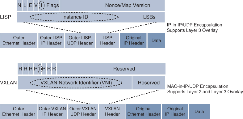
Figure 23-4 LISP and VXLAN Packet Format Comparison
The original VXLAN specification was enhanced for SD-Access to support Cisco TrustSec Scalable Group Tags (SGTs). This was accomplished by adding new fields to the first 4 bytes of the VXLAN header in order to transport up to 64,000 SGT tags. The new VXLAN format is called VXLAN Group Policy Option (VXLAN-GPO), and it is defined in the IETF draft draft-smith-vxlan-group-policy-05.
Figure 23-5 illustrates the VXLAN-GPO format compared to the original VXLAN format.
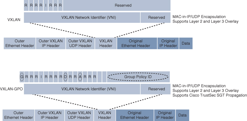
Figure 23-5 VXLAN and VXLAN-GPO Packet Format Comparison
The new fields in the VXLAN-GPO packet format include the following:
Group Policy ID: 16-bit identifier that is used to carry the SGT tag.
Group Based Policy Extension Bit (G Bit): 1-bit field that, when set to 1, indicates an SGT tag is being carried within the Group Policy ID field and set to 0 when it is not.
Don’t Learn Bit (D Bit): 1-bit field that when set to 1 indicates that the egress virtual tunnel endpoint (VTEP) must not learn the source address of the encapsulated frame.
Policy Applied Bit (A Bit): 1-bit field that is only defined as the A bit when the G bit field is set to 1. When the A bit is set to 1, it indicates that the group policy has already been applied to this packet, and further policies must not be applied by network devices. When it is set to 0, group policies must be applied by network devices, and they must set the A bit to 1 after the policy has been applied.
SD-Access Fabric Policy Plane
The fabric policy plane is based on Cisco TrustSec. Cisco TrustSec SGT tags are assigned to authenticated groups of users or end devices. Network policy (for example, ACLs, QoS) is then applied throughout the SD-Access fabric, based on the SGT tag instead of a network address (MAC, IPv4, or IPv6). This allows for the creation of network policies such as security, quality of service (QoS), policy-based routing (PBR), and network segmentation, based only on the SGT tag and not the network address (MAC, IPv4, or IPv6) of the user or endpoint.
TrustSec SGT tags provide several advantages for Cisco SD-Access, such as
Support for both network-based segmentation using VNs (VRF instances) and group-based segmentation (policies)
Network address-independent group-based policies based on SGT tags rather than MAC, IPv4, or IPv6 addresses, which reduces complexity
Dynamic enforcement of group-based policies, regardless of location for both wired and wireless traffic
Policy constructs over a legacy or third-party network using VXLAN
Extended policy enforcement to external networks (such as cloud or data center networks) by transporting the tags to Cisco TrustSec-aware devices using SGT Exchange Protocol (SXP)
SD-Access Fabric Roles and Components
The operation of the SD-Access fabric requires multiple different device roles, each with a specific set of responsibilities. Each SD-Access-enabled network device must be configured for one (or more) of these roles. During the planning and design phase, it is important to understand the fabric roles and to select the most appropriate network devices for each role.
There are five basic device roles in the fabric overlay:
Control plane node: This node contains the settings, protocols, and mapping tables to provide the endpoint-to-location (EID-to-RLOC) mapping system for the fabric overlay.
Fabric border node: This fabric device (for example, core layer device) connects external Layer 3 networks to the SDA fabric.
Fabric edge node: This fabric device (for example, access or distribution layer device) connects wired endpoints to the SDA fabric.
Fabric WLAN controller (WLC): This fabric device connects APs and wireless endpoints to the SDA fabric.
Intermediate nodes: These are intermediate routers or extended switches that do not provide any sort of SD-Access fabric role other than underlay services.
Figure 23-6 illustrates the different SD-Access fabric design roles and how nodes in the fabric can play multiple roles. For example, the core layer routers in this figure are acting as fabric border nodes and control plane nodes.
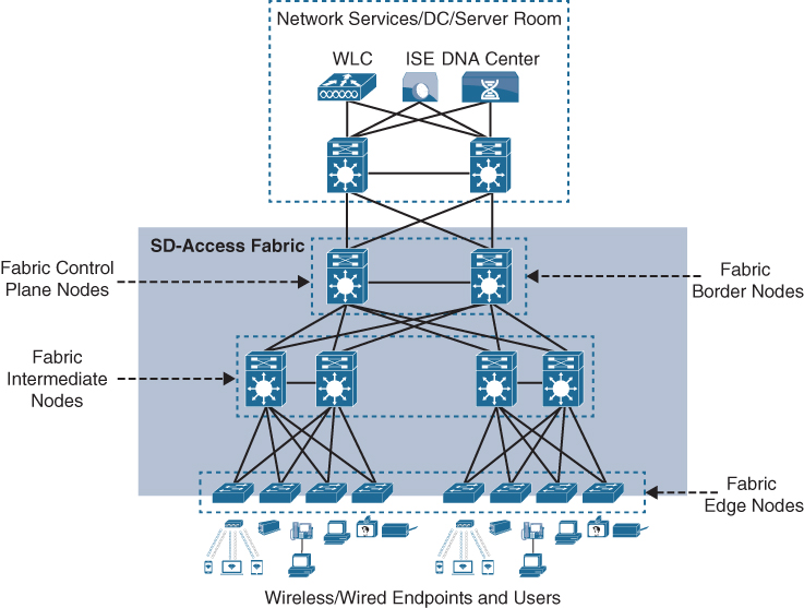
Figure 23-6 SD-Access Fabric Roles
Fabric Edge Nodes
A fabric edge node provides onboarding and mobility services for wired users and devices (including fabric-enabled WLCs and APs) connected to the fabric. It is a LISP tunnel router (xTR) that also provides the anycast gateway, endpoint authentication, and assignment to overlay host pools (static or DHCP), as well as group-based policy enforcement (for traffic to fabric endpoints).
A fabric edge first identifies and authenticates wired endpoints (through 802.1x), in order to place them in a host pool (SVI and VRF instance) and scalable group (SGT assignment). It then registers the specific EID host address (that is, MAC, /32 IPv4, or /128 IPv6) with the control plane node.
A fabric edge provides a single Layer 3 anycast gateway (that is, the same SVI with the same IP address on all fabric edge nodes) for its connected endpoints and also performs the encapsulation and de-encapsulation of host traffic to and from its connected endpoints.
Fabric Control Plane Node
A fabric control plane node is a LISP map server/resolver (MS/MR) with enhanced functions for SD-Access, such as fabric wireless and SGT mapping. It maintains a simple host tracking database to map EIDs to RLOCs.
The control plane (host database) maps all EID locations to the current fabric edge or border node, and it is capable of multiple EID lookup types (IPv4, IPv6, or MAC).
The control plane receives registrations from fabric edge or border nodes for known EID prefixes from wired endpoints and from fabric mode WLCs for wireless clients. It also resolves lookup requests from fabric edge or border nodes to locate destination EIDs and updates fabric edge nodes and border nodes with wired and wireless client mobility and RLOC information.
A control plane node must be either a Cisco switch or a router operating either inside or outside the SD-WAN fabric.
Fabric Border Nodes
Fabric border nodes are LISP proxy tunnel routers (PxTRs) that connect external Layer 3 networks to the SD-Access fabric and translate reachability and policy information, such as VRF and SGT information, from one domain to another.
There are three types of border nodes:
Internal border (rest of company): Connects only to the known areas of the organization (for example, WLC, firewall, data center).
Default border (outside): Connects only to unknown areas outside the organization. This border node is configured with a default route to reach external unknown networks such as the Internet or the public cloud that are not known to the control plane nodes.
Internal + default border (anywhere): Connects transit areas as well as known areas of the company. This is basically a border that combines internal and default border functionality into a single node.
Fabric Wireless Controller (WLC)
A fabric-enabled WLC connects APs and wireless endpoints to the SD-Access fabric. The WLC is external to the fabric and connects to the SD-Access fabric through an internal border node. A fabric WLC node provides onboarding and mobility services for wireless users and endpoints connected to the SD-Access fabric. A fabric WLC also performs PxTR registrations to the fabric control plane (on behalf of the fabric edges) and can be thought of as a fabric edge for wireless clients. The control plane node maps the host EID to the current fabric access point and fabric edge node location the access point is attached to.
In traditional wireless deployments, the WLC is typically centralized, and all control plane and data plane (wireless client data) traffic needs to be tunneled to the WLC through the Control and Provisioning of Wireless Access Points (CAPWAP) tunnel. In SD-Access, the wireless control plane remains centralized, but the data plane is distributed using VXLAN directly from the fabric-enabled APs. Figure 23-7 illustrates a traditional wireless deployment compared to an SD-Access wireless deployment.

Figure 23-7 Traditional Wireless and SD-Access Wireless Deployments
Fabric APs establish a VXLAN tunnel to the fabric edge to transport wireless client data traffic through the VXLAN tunnel instead of the CAPWAP tunnel. For this to work, the AP must be directly connected to the fabric edge or a fabric extended node. Using a VXLAN tunnel to transport the wireless data traffic increases performance and scalability because the wireless client data traffic doesn’t need to be tunneled to the WLC via CAPWAP, as in traditional wireless deployments because the routing decision is taken directly by the fabric edge. In addition, SGT- and VRF-based policies for wireless users on fabric SSIDs are applied at the fabric edge in the same way as for wired users. Wireless clients (SSIDs) use regular host pools for traffic and policy enforcement (the same as wired clients), and the fabric WLC registers client EIDs with the control plane node (as located on the edge).
SD-Access Fabric Concepts
Better understanding the benefits and operation of Cisco SD-Access requires reviewing the following concepts related to how the multiple technologies that are used by the SD-WAN solution operate and interact in SD-Access:
Virtual network (VN): The VN provides virtualization at the device level, using VRF instances to create multiple Layer 3 routing tables. VRF instances provide segmentation across IP addresses, allowing for overlapped address space and traffic segmentation. In the control plane, LISP instance IDs are used to maintain separate VRF instances. In the data plane, edge nodes add a VXLAN VNID to the fabric encapsulation.
Host pool: A host pool is a group of endpoints assigned to an IP pool subnet in the SDA-Access fabric. Fabric edge nodes have a Switched Virtual Interface (SVI) for each host pool to be used by endpoints and users as their default gateway. The SD-Access fabric uses EID mappings to advertise each host pool (per instance ID), which allows host-specific (/32, /128, or MAC) advertisement and mobility. Host pools can be assigned dynamically (using host authentication, such as 802.1x) and/or statically (per port).
Scalable group: A scalable group is a group of endpoints with similar policies. The SD-Access policy plane assigns every endpoint (host) to a scalable group using TrustSec SGT tags. Assignment to a scalable group can be either static per fabric edge port or using dynamic authentication through AAA or RADIUS using Cisco ISE. The same scalable group is configured on all fabric edge and border nodes. Scalable groups can be defined in Cisco DNA Center and/or Cisco ISE and are advertised through Cisco TrustSec. There is a direct one-to-one relationship between host pools and scalable groups. Therefore, the scalable groups operate within a VN by default. The fabric edge and border nodes include the SGT tag ID in each VXLAN header, which is carried across the fabric data plane. This keeps each scalable group separate and allows SGACL policy and enforcement.
Anycast gateway: The anycast gateway provides a pervasive Layer 3 default gateway where the same SVI is provisioned on every edge node with the same SVI IP and MAC address. This allows an IP subnet to be stretched across the SD-Access fabric. For example, if the subnet 10.1.0.0/24 is provisioned on an SD-Access fabric, this subnet will be deployed across all of the edge nodes in the fabric, and an endpoint located in that subnet can be moved to any edge node within the fabric without a change to its IP address or default gateway. This essentially stretches these subnets across all of the edge nodes throughout the fabric, thereby simplifying the IP address assignment and allowing fewer but larger IP subnets to be deployed. In essence, the fabric behaves like a logical switch that spans multiple buildings, where an endpoint can be unplugged from one port and plugged into another port on a different building, and it will seem as if the endpoint is connecting to the same logical switch, where it can still reach the same SVI and other endpoints in the same VLAN.
Controller Layer
The controller layer provides all of the management subsystems for the management layer, and this is all provided by Cisco DNA Center and Cisco ISE. Figure 23-8 illustrates the different components that comprise the controller layer and how they interact with each other as well as with the campus fabric.
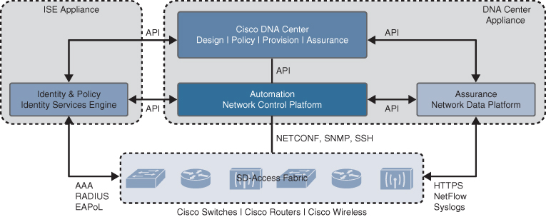
Figure 23-8 SD-Access Main Components
There are three main controller subsystems:
Cisco Network Control Platform (NCP): This is a subsystem integrated directly into Cisco DNA Center that provides all the underlay and fabric automation and orchestration services for the physical and network layers. NCP configures and manages Cisco network devices using NETCONF/YANG, Simple Network Management Protocol (SNMP), SSH/Telnet, and so on and then provides network automation status and other information to the management layer.
Cisco Network Data Platform (NDP): NDP is a data collection and analytics and assurance subsystem that is integrated directly into Cisco DNA Center. NDP analyzes and correlates various network events through multiple sources (such as NetFlow and Switched Port Analyzer [SPAN]) and identifies historical trends. It uses this information to provide contextual information to NCP and ISE, and it provides network operational status and other information to the management layer.
Cisco Identity Services Engine (ISE): The basic role of ISE is to provide all the identity and policy services for the physical layer and network layer. ISE provides network access control (NAC) and identity services for dynamic endpoint-to-group mapping and policy definition in a variety of ways, including using 802.1x, MAC Authentication Bypass (MAB), and Web Authentication (WebAuth). ISE also collects and uses the contextual information shared from NDP and NCP (and other systems, such as Active Directory and AWS). ISE then places the profiled endpoints into the correct scalable group and host pool. It uses this information to provide information to NCP and NDP, so the user (management layer) can create and manage group-based policies. ISE is also responsible for programming group-based policies on the network devices.
Cisco ISE and the DNA Center (NCP and NDP) integrate with each other to share contextual information through APIs between themselves, and this contextual information is then provided to the user management layer:
The NDP subsystem shares contextual analytics information with Cisco ISE and NCP subsystems and provides this information to the user (management layer).
The NCP subsystem integrates directly with Cisco ISE and NDP subsystems to provide contextual automation information between them.
Cisco ISE integrates directly with Cisco NCP and NDP subsystems (Cisco DNA Center) to provide contextual identity and policy information.
Management Layer
The Cisco DNA Center management layer is the user interface/user experience (UI/UX) layer, where all the information from the other layers is presented to the user in the form of a centralized management dashboard. It is the intent-based networking aspect of Cisco DNA.
A full understanding of the network layer (LISP, VXLAN, and Cisco TrustSec) or controller layer (Cisco NCP, NDP, and ISE) is not required to deploy the fabric in SD-Access. Nor is there a requirement to know how to configure each individual network device and feature to create the consistent end-to-end behavior offered by SD-Access.
The management layer abstracts all the complexities and dependencies of the other layers and provides the user with a simple set of GUI tools and workflows to easily manage and operate the entire Cisco DNA network (hence the name Cisco DNA Center).
Cisco DNA Center applications are designed for simplicity and are based on the primary workflows defined by Cisco DNA Center: design, policy, provision, and assurance.
Cisco DNA Design Workflow
The Cisco DNA design workflow provides all the tools needed to logically define the SD-Access fabric. The following are some of the Cisco DNA design tools:
Network Hierarchy: Used to set up geolocation, building, and floorplan details and associate them with a unique site ID.
Network Settings: Used to set up network servers (such as DNS, DHCP, and AAA), device credentials, IP management, and wireless settings.
Image Repository: Used to manage the software images and/or maintenance updates, set version compliance, and download and deploy images.
Network Profiles: Used to define LAN, WAN, and WLAN connection profiles (such as SSID) and apply them to one or more sites.
Figure 23-9 illustrates the DNA Center design workflow on the DNA Center dashboard.

Figure 23-9 DNA Center Design Workflow
Cisco DNA Policy Workflow
The Cisco DNA policy workflow provides all the tools to logically define Cisco DNA policies. The following are some of the Cisco DNA policy tools:
Dashboard: Used to monitor all the VNs, scalable groups, policies, and recent changes.
Group-Based Access Control: Used to create group-based access control policies, which are the same as SGACLs. Cisco DNA Center integrates with Cisco ISE to simplify the process of creating and maintaining SGACLs.
IP-Based Access Control: Used to create IP-based access control policy to control the traffic going into and coming out of a Cisco device in the same way that an ACL does.
Application: Used to configure QoS in the network through application policies.
Traffic Copy: Used to configure Encapsulated Remote Switched Port Analyzer (ERSPAN) to copy the IP traffic flow between two entities to a specified remote destination for monitoring or troubleshooting purposes.
Virtual Network: Used to set up the virtual networks (or use the default VN) and associate various scalable groups.
Figure 23-10 illustrates the DNA Center policy workflow on the DNA Center dashboard.
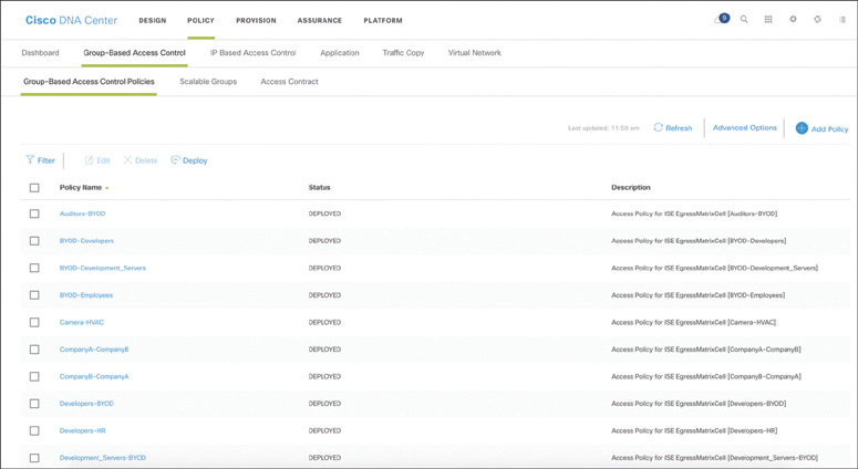
Figure 23-10 DNA Center Policy Workflow
Cisco DNA Provision Workflow
The Cisco DNA provision workflow provides all the tools to deploy the Cisco SD-Access fabric. The following are some of the Cisco DNA provision tools:
Devices: Used to assign devices to a site ID, confirm or update the software version, and provision the network underlay configurations.
Fabrics: Used to set up the fabric domains (or use the default LAN fabric).
Fabric Devices: Used to add devices to the fabric domain and specify device roles (such as control plane, border, edge, and WLC).
Host Onboarding: Used to define the host authentication type (static or dynamic) and assign host pools (wired and wireless) to various VNs.
Figure 23-11 illustrates the DNA Center provision workflow on the DNA Center dashboard.

Figure 23-11 DNA Center Provision Workflow
Cisco DNA Assurance Workflow
The Cisco DNA assurance workflow provides all the tools to manage the SD-Access fabric. The following are some of the Cisco DNA assurance tools:
Dashboard: Used to monitor the global health of all (fabric and non-fabric) devices and clients, with scores based on the status of various sites.
Client 360: Used to monitor and resolve client-specific status and issues (such as onboarding and app experience), with links to connected devices.
Devices 360: Used to monitor and resolve device-specific status and issues (such as resource usage and loss and latency), with links to connected clients.
Issues: Used to monitor and resolve open issues (reactive) and/or developing trends (proactive) with clients and devices at various sites.
Figure 23-12 illustrates the DNA Center assurance workflow on the DNA Center dashboard.
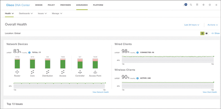
Figure 23-12 DNA Center Assurance Workflow
Software-Defined WAN (SD-WAN)
Managing enterprise networks is becoming more complex, with customers embracing a multicloud approach, applications moving to the cloud, mobile and IoT devices growing exponentially in the network, and the Internet edge moving to the branch. This digital transformation is powering the adoption of SD-WAN by customers looking to do the following:
Lower costs and reduce risks with simple WAN automation and orchestration.
Extend their enterprise networks (such as branch or on-premises) seamlessly into the public cloud.
Provide optimal user experience for SaaS applications.
Leverage a transport-independent WAN for lower cost and higher diversity. This means the underlay network can be any type of IP-based network, such as the Internet, MPLS, 3G/4G LTE, satellite, or dedicated circuits.
Enhance application visibility and use that visibility to improve performance with intelligent path control to meet SLAs for business-critical and real-time applications.
Provide end-to-end WAN traffic segmentation and encryption for protecting critical enterprise compute resources.
Cisco currently offers two SD-WAN solutions:
Cisco SD-WAN (based on Viptela): This is the preferred solution for organizations that require an SD-WAN solution with cloud-based initiatives that provides granular segmentation, advanced routing, advanced security, and complex topologies while connecting to cloud instances.
Meraki SD-WAN: This is the recommended solution for organizations that require unified threat management (UTM) solutions with SD-WAN functionality or that are existing Cisco Meraki customers looking to expand to SD-WAN. UTM is an all-in-one security solution delivered in a single appliance and typically includes the following security features: firewall, VPN, intrusion prevention, antivirus, antispam, and web content filtering.
The two SD-WAN solutions can achieve similar design goals, but this chapter covers only Cisco SD-WAN based on Viptela.
Cisco SD-WAN Architecture
Cisco SD-WAN (based on Viptela) is a cloud-delivered overlay WAN architecture that facilitates digital and cloud transformation for enterprises, and it addresses all the customer requirements mentioned earlier. Figure 23-13 illustrates Cisco’s SD-WAN solution architecture.

Figure 23-13 SD-WAN Solution Architecture
Figure 23-13 shows how SD-WAN can be used to provide secure connectivity to remote offices, branch offices, campus networks, data centers, and the cloud over any type of IP-based underlay transport network, such as the Internet, 3G/4G LTE, and MPLS. It also illustrates how some of the components to manage the SD-WAN fabric can be deployed on a data center, private cloud, or public cloud.
The Cisco SD-WAN solution has four main components and an optional analytics service:
vManage Network Management System (NMS): This is a single pane of glass (GUI) for managing the SD-WAN solution.
vSmart controller: This is the brains of the solution.
SD-WAN routers: SD-WAN involves both vEdge and cEdge routers.
vBond orchestrator: This authenticates and orchestrates connectivity between SD-WAN routers and vSmart controllers.
vAnalytics: This is an optional analytics and assurance service.
vManage NMS
The vManage NMS is a single pane of glass network management system (NMS) GUI that is used to configure and manage the full SD-WAN solution. It enables centralized provisioning and simplifies network changes.
vSmart Controller
vSmart controllers (which are the brains of the SD-WAN solution) have pre-installed credentials that allow them to authenticate every SD-WAN router that comes online. These credentials ensure that only authenticated devices are allowed access to the SD-WAN fabric. After successful authentication, each vSmart controller establishes a permanent DTLS tunnel to each SD-WAN router in the SD-WAN fabric and uses these tunnels to establish Overlay Management Protocol (OMP) neighborships with each SD-WAN router. OMP is a proprietary routing protocol similar to BGP that can advertise routes, next hops, keys, and policy information needed to establish and maintain the SD-WAN fabric.
The vSmart controller processes the OMP routes learned from the SD-WAN routers (or other vSmart controllers) to determine the network topology and calculate the best routes to network destinations. Then it advertises reachability information learned from these routes to all the SD-WAN routers in the SD-WAN fabric.
vSmart controllers also implement all the control plane policies created on vManage, such as service chaining, traffic engineering, and segmentation per VPN topology. For example, when a policy is created on vManage for an application (such as YouTube) that requires no more than 1% loss and 150 ms latency, that policy is downloaded to the vSmart controller. vSmart converts the policy into a format that all the SD-WAN routers in the fabric can understand, and it automatically implements the policy on all SD-WAN routers without the need to rely on a CLI. The vSmart controller also works in conjunction with the vBond orchestrator to authenticate the devices as they join the network and to orchestrate connectivity between the SD-WAN routers.
Cisco SD-WAN Routers (vEdge and cEdge)
Cisco SD-WAN routers deliver the essential WAN, security, and multicloud capabilities of the Cisco SD-WAN solution, and they are available as hardware, software, cloud, or virtualized routers that sit at the perimeter of a site, such as a remote office, branch office, campus, or data center.
SD-WAN routers support standard router features, such as OSPF, BGP, ACLs, QoS, and routing policies, in addition to the SD-WAN overlay control and data plane functions. Each SD-WAN router automatically establishes a secure Datagram Transport Layer Security (DTLS) connection with the vSmart controller and forms an OMP neighborship over the tunnel to exchange routing information. It also establishes standard IPsec sessions with other SD-WAN routers in the fabric. SD-WAN routers have local intelligence to make site-local decisions regarding routing, high availability (HA), interfaces, ARP management, and ACLs. The vSmart controller provides remote site routes and the reachability information necessary to build the SD-WAN fabric.
There are two different SD-WAN router options available for the Cisco SD-WAN solution:
vEdge: The original Viptela platforms running Viptela software.
cEdge: Viptela software integrated with Cisco IOS-XE. This is supported on CSR, ISR, ASR1K, ENCS, and the cloud-enabled CSRv and ISRv platforms.
The SD-WAN image based on Cisco IOS XE software is not a standard Cisco IOS XE release. Only a selected set of Cisco IOS XE features that make sense for SD-WAN were ported over into the IOS XE SD-WAN image. vManage enables provisioning, configuration, and troubleshooting of IOS XE SD-WAN routers in exactly the same way as vEdge routers.
A main differentiator between SD-WAN cEdge routers and vEdge routers is that they support advanced security features, as demonstrated in Table 23-2.
Table 23-2 SD-WAN Router Advanced Security Feature Comparison
Feature |
cEdge |
vEdge |
Cisco AMP and AMP Threat Grid |
Yes |
No |
Enterprise Firewall |
Yes |
Yes |
Cisco Umbrella DNS Security |
Yes |
Yes |
URL filtering |
Yes |
No |
The Snort intrusion prevention system (IPS) |
Yes |
No |
Embedded platform security (including the Cisco Trust Anchor module) |
Yes |
No |
vBond Orchestrator
The vBond orchestrator authenticates the vSmart controllers and the SD-WAN routers and orchestrates connectivity between them. It is the only device that must have a public IP address so that all SD-WAN devices in the network can connect to it. A vBond orchestrator is an SD-WAN router that only performs vBond orchestrator functions.
The major components of the vBond orchestrator are:
Control plane connection: Each vBond orchestrator has a permanent control plane connection over a DTLS tunnel with each vSmart controller. In addition, the vBond orchestrator uses DTLS connections to communicate with SD-WAN routers when they come online, to authenticate them and to facilitate their ability to join the network. Basic authentication of an SD-WAN router is done using certificates and RSA cryptography.
NAT traversal: The vBond orchestrator facilitates the initial orchestration between SD-WAN routers and vSmart controllers when one or both of them are behind NAT devices. Standard peer-to-peer techniques are used to facilitate this orchestration.
Load balancing: In a domain with multiple vSmart controllers, the vBond orchestrator automatically performs load balancing of SD-WAN routers across the vSmart controllers when routers come online.
vAnalytics
vAnalytics is an optional analytics and assurance service that has many advanced capabilities, including the following:
Visibility into applications and infrastructure across the WAN
Forecasting and what-if analysis
Intelligent recommendations
These capabilities can bring many benefits to SD-WAN that are not possible without vAnalytics. For example, if a branch office is experiencing latency or loss on its MPLS link, vAnalytics detects this, and it compares that loss or latency with information on other organizations in the area that it is also monitoring to see if they are also having that same loss and latency in their circuits. If they are, vAnalytics can then report the issue with confidence to the SPs. vAnalytics can also help predict how much bandwidth is truly required for any location, and this is useful in deciding whether a circuit can be downgraded to a lower bandwidth to reduce costs.
Among the SD-WAN components, the SD-WAN routers and the vBond orchestrator are available as physical appliances and VMs, whereas vManage and vSmart are only available as VMs.
All of the VMs, including the CSRv, ISRv, and vEdge cloud routers, can be hosted on-premises using ESXi or KVM, or they can be hosted in AWS and Microsoft Azure.
Cisco SD-WAN Cloud OnRamp
Traditional enterprise WAN architectures are not designed for the cloud. As organizations adopt more SaaS applications such as Office 365 and public cloud infrastructures such as AWS and Microsoft Azure, the current network infrastructure poses major problems related to the level of complexity and end-user experience.
The Cisco SD-WAN solution includes a set of functionalities addressing optimal cloud SaaS application access and IaaS connectivity, called Cloud OnRamp. Cloud OnRamp delivers the best application quality of experience (QoE) for SaaS applications by continuously monitoring SaaS performance across diverse paths and selecting the best-performing path based on performance metrics (jitter, loss, and delay). In addition, it simplifies hybrid cloud and multicloud IaaS connectivity by extending the SD-WAN fabric to the public cloud while at the same time increasing high availability and scale.
Cloud OnRamp for SaaS
SaaS applications reside mainly on the Internet, and to be able to achieve optimal SaaS application performance, the best-performing Internet exit point needs to be selected.
Figure 23-14 illustrates a remote site with dual direct Internet access (DIA) circuits from two different Internet service providers (ISP1 and ISP2). When Cloud OnRamp for SaaS is configured for an SaaS application on vManage, the SD-WAN router at the remote site starts sending small HTTP probes to the SaaS application through both DIA circuits to measure latency and loss. Based on the results, the SD-WAN router will know which circuit is performing better (in this case, ISP2) and sends the SaaS application traffic out that circuit. The process of probing continues, and if a change in performance characteristics of ISP2’s DIA circuit occurs (for example, due to loss or latency), the remote site SD-WAN router makes an appropriate forwarding decision.
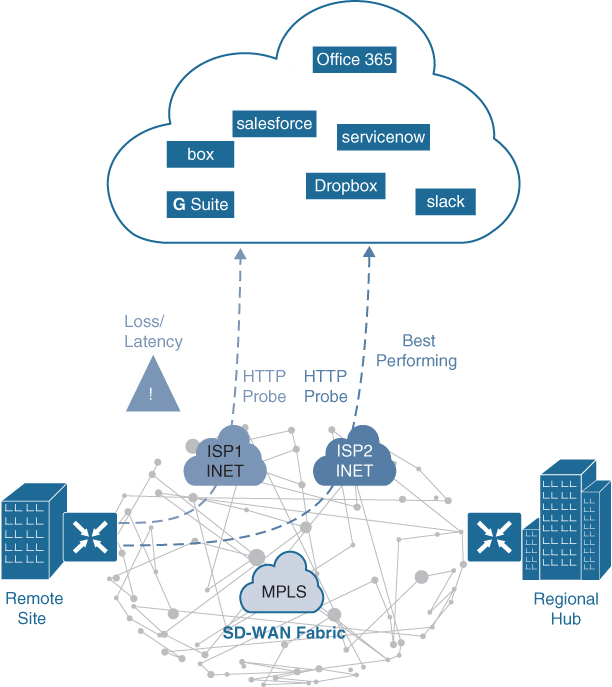
Figure 23-14 Cloud OnRamp for SaaS with Dual DIA
Figure 23-15 illustrates another example of Cloud OnRamp for SaaS. In this case, the remote site has a single DIA circuit to ISP1 and an SD-WAN fabric DTLS session to the regional hub.
Much as in the previous case, Cloud OnRamp for SaaS can be configured on the vManage NMS and can become active on the remote site SD-WAN router. However, in this case, Cloud OnRamp for SaaS also gets enabled on the regional hub SD-WAN router and is designated as the gateway node. Quality probing service via HTTP toward the cloud SaaS application of interest starts on both the remote site SD-WAN and the regional hub SD-WAN.

Figure 23-15 Cloud OnRamp for SaaS DIA and Gateway
Unlike the HTTP probe sent toward the SaaS application via the DIA link, Bidirectional Forwarding Detection (BFD) runs through the DTLS session between the remote site and the regional hub. BFD is a detection protocol originally designed to provide fast forwarding path failure detection times between two adjacent routers. For SD-WAN, it is leveraged to detect path liveliness (up/down) and measure quality (loss/latency/jitter and IPsec tunnel MTU).
For SaaS over DIA, BFD is not used because there is no SD-WAN router on the SaaS side to form a BFD session with. The regional hub SD-WAN router reports its HTTP connection loss and latency characteristics to the remote site SD-WAN router in an Overlay Management Protocol (OMP) message exchange through the vSmart controllers. At this time, the remote site SD-WAN router can evaluate the performance characteristics of its local DIA circuit compared to the performance characteristics reported by the regional hub SD-WAN. It also takes into consideration the loss and latency incurred by traversing the SD-WAN fabric between the remote site and the hub site (calculated using BFD) and then makes an appropriate forwarding decision, sending application traffic down the best-performing path toward the cloud SaaS application of choice.
The quality of cloud SaaS application connection is quantified as a Viptela Quality of Experience (vQoE) score on a scale of 0 to 10, with 0 being the worst quality and 10 being the best. vQoE can be observed in the vManage GUI.
Cloud OnRamp for IaaS
Multicloud is now the new norm for enterprises. With multicloud, certain enterprise workloads remain within the boundaries of the private data centers, while others are hosted in the public cloud environments, such as AWS and Microsoft Azure. This approach provides enterprises the greatest flexibility in consuming compute infrastructure, as required.
With the Cisco SD-WAN solution, ubiquitous connectivity, zero-trust security, end-to-end segmentation, and application-aware QoS policies can be extended into the IaaS environments by using SD-WAN cloud routers, as illustrated in Figure 23-16. The transport-independent capability of the Cisco SD-WAN solution allows the use of a variety of connectivity methods by securely extending the SD-WAN fabric into the public cloud environment across any underlay transport network. These include the Internet, MPLS, 3G/4G LTE, satellite, and dedicated circuits such as AWS’s DX and Microsoft Azure’s ER.
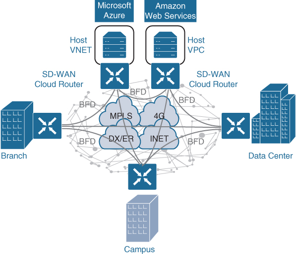
Figure 23-16 Cloud OnRamp for IaaS
Exam Preparation Tasks
As mentioned in the section “How to Use This Book” in the Introduction, you have a couple of choices for exam preparation: the exercises here, Chapter 30, “Final Preparation,” and the exam simulation questions in the Pearson Test Prep Software Online.
Review All Key Topics
Review the most important topics in the chapter, noted with the key topics icon in the outer margin of the page. Table 23-3 lists these key topics and the page number on which each is found.
Table 23-3 Key Topics for Chapter 23
Key Topic Element |
Description |
Page |
List |
SD-Access capabilities, features, and functionalities |
|
Cisco SD-Access architecture |
||
Section |
Underlay network |
|
List |
Types of underlay networks supported by SD-Access |
|
Section |
Overlay network (SD-Access fabric) |
|
List |
SD-Access basic planes of operation |
|
Section |
SD-Access control plane description |
|
Section |
SD-Access fabric data plane |
|
Paragraph |
VXLAN-GPO definition |
|
Section |
SD-Access fabric policy plane |
|
List |
SD-Access fabric roles |
|
Section |
Fabric edge nodes |
|
Section |
Fabric control plane node |
|
Section |
Fabric border nodes |
|
List |
Types of border nodes |
|
Section |
Fabric wireless controller (WLC) |
|
List |
SD-Access fabric concepts |
|
Section |
Controller layer |
|
List |
SD-Access three main controller subsystems |
|
Section |
Management layer |
|
List |
SD-WAN main components |
|
Section |
vManage NMS |
|
Section |
vSmart controller |
|
Section |
Cisco SD-WAN routers (vEdge and cEdge) |
|
SD-WAN Router Advanced Security Feature Comparison |
||
Section |
vBond orchestrator |
|
Section |
SD-WAN Cloud OnRamp |
Complete Tables and Lists from Memory
Print a copy of Appendix B, “Memory Tables” (found on the companion website), or at least the section for this chapter, and complete the tables and lists from memory. Appendix C, “Memory Tables Answer Key,” also on the companion website, includes completed tables and lists you can use to check your work.
Define Key Terms
Define the following key terms from this chapter and check your answers in the Glossary:
application programming interface (API)
Cisco Advanced Malware Protection (AMP)
Datagram Transport Layer Security (DTLS)
Location/ID Separation Protocol (LISP)
MAC Authentication Bypass (MAB)
map server/map resolver (MS/MR)
Network Configuration Protocol (NETCONF)/YANG
Security Group Access Control List (SGACL)
virtual tunnel endpoint (VTEP)
VXLAN Group Policy Option (GPO)