Appendix C. Memory Tables
Chapter 7
Table 7-2 EIGRP Terminology
Term |
Definition |
|
The route with the lowest path metric to reach a destination. |
Successor |
|
|
The metric value for the lowest-metric path to reach a destination. The feasible distance is calculated locally using the formula shown in the “Path Metric Calculation” section, later in this chapter. The FD calculated by R1 for the 10.4.4.0/24 network is 3328 (that is, 256+256+2816). |
|
The distance reported by a router to reach a prefix. The reported distance value is the feasible distance for the advertising router. R3 advertises the 10.4.4.0/24 prefix with an RD of 3072. R4 advertises the 10.4.4.0/24 to R1 and R2 with an RD of 2816. |
Feasibility condition |
|
Feasible successor |
A route that satisfies the feasibility condition and is maintained as a backup route. The feasibility condition ensures that the backup route is loop free. The route R1→R4 is the feasible successor because the RD 2816 is lower than the FD 3328 for the R1→R3→R4 path. |
Table 7-3 EIGRP Packet Types
Type |
Packet Name |
Function |
1 |
|
Used for discovery of EIGRP neighbors and for detecting when a neighbor is no longer available |
2 |
Request |
|
3 |
|
Used to transmit routing and reachability information with other EIGRP neighbors |
4 |
Query |
|
5 |
Reply |
|
Chapter 8
Table 8-2 OSPF Packet Types
Type |
Packet Name |
Functional Overview |
1 |
|
These packet are for discovering and maintaining neighbors. Packets are sent out periodically on all OSPF interfaces to discover new neighbors while ensuring that other adjacent neighbors are still online. |
2 |
|
These packet are for summarizing database contents. Packets are exchanged when an OSPF adjacency is first being formed. These packets are used to describe the contents of the LSDB. |
3 |
|
These packet are for database downloads. When a router thinks that part of its LSDB is stale, it may request a portion of a neighbor’s database by using this packet type. |
4 |
|
These packets are for database updates. This is an explicit LSA for a specific network link and normally is sent in direct response to an LSR. |
5 |
|
These packet are for flooding acknowledgment. These packets are sent in response to the flooding of LSAs, thus making flooding a reliable transport feature. |
Table 8-9 OSPF Network Types
Type |
Description |
DR/BDR Field in OSPF Hellos |
Timers |
|
Default setting on OSPF-enabled Ethernet links |
Yes |
|
|
Default setting on OSPF-enabled Frame Relay main interface or Frame Relay multipoint subinterfaces |
|
Hello: 30Wait: 120Dead: 120 |
Point-to-point |
Default setting on OSPF-enabled Frame Relay point-to-pointsubinterfaces. |
|
|
|
Not enabled by default on any interface type. Interface is advertised as a host route (/32) and sets the next-hop addressto the outbound interface. Primarily used for hub-and-spoke topologies. |
No |
Hello: 30Wait: 120Dead: 120 |
Loopback |
|
N/A |
N/A |
Chapter 13
Table 13-2 IP Multicast Addresses Assigned by IANA
Designation |
Multicast Address Range |
Local network control block |
|
Internetwork control block |
|
Ad hoc block I |
224.0.2.0 to 224.0.255.255 |
Reserved |
224.1.0.0 to 224.1.255.255 |
SDP/SAP block |
224.2.0.0 to 224.2.255.255 |
Ad hoc block II |
224.3.0.0 to 224.4.255.255 |
Reserved |
224.5.0.0 to 224.255.255.255 |
Reserved |
225.0.0.0 to 231.255.255.255 |
|
232.0.0.0 to 232.255.255.255 |
GLOP block |
233.0.0.0 to 233.251.255.255 |
Ad hoc block III |
233.252.0.0 to 233.255.255.255 |
Reserved |
234.0.0.0 to 238.255.255.255 |
Administratively scoped block |
|
Table 13-3 Well-Known Reserved Multicast Addresses
IP Multicast Address |
Description |
224.0.0.0 |
Base address (reserved) |
224.0.0.1 |
All hosts in this subnet (all-hosts group) |
224.0.0.2 |
All routers in this subnet |
224.0.0.5 |
All OSPF routers (AllSPFRouters) |
224.0.0.6 |
All OSPF DRs (AllDRouters) |
224.0.0.9 |
All RIPv2 routers |
224.0.0.10 |
All EIGRP routers |
|
All PIM routers |
224.0.0.18 |
VRRP |
|
IGMPv3 |
224.0.0.102 |
HSRPv2 and GLBP |
224.0.1.1 |
NTP |
|
Cisco-RP-Announce (Auto-RP) |
|
Cisco-RP-Discovery (Auto-RP) |
The IGMP message format fields are defined as follows:
Type: This field describes five different types of IGMP messages used by routers and receivers:
_____________________________ (type value 0x16) is a message type alsocommonly referred to as an IGMP join; it is used by receivers to join a multicast group or to respond to a local router’s membership query message.
Version 1 membership report (type value 0x12) is used by receivers for backward compatibility with IGMPv1.
Version 2 leave group (type value 0x17) is used by receivers to indicate they want to stop receiving multicast traffic for a group they joined.
_____________________________ (type value 0x11) is sent periodically sent to the all-hosts group address 224.0.0.1 to see whether there are any receivers in the attached subnet. It sets the group address field to 0.0.0.0.
Group specific query (type value 0x11) is sent in response to a leave groupmessage to the group address the receiver requested to leave. The group addressis the destination IP address of the IP packet and the group address field.
_____________________________: This field is set only in general and group-specific membership query messages (type value 0x11); it specifies the maximum allowed time before sending a responding report in units of one-tenth of a second. In all othermessages, it is set to 0x00 by the sender and ignored by receivers.
_____________________________: This field is the 16-bit 1s complement of the 1s complement sum of the IGMP message. This is the standard checksum algorithm used by TCP/IP.
_____________________________: This field is set to 0.0.0.0 in general query messages and is set to the group address in group-specific messages. Membership reportmessages carry the address of the group being reported in this field; group leavemessages carry the address of the group being left in this field.
The following list defines the common PIM terminology illustrated in Figure 13-14:
Reverse Path Forwarding (RPF) interface: _____________________________________
____________________________________________________________________
____________________________________________________________________
____________________________________________________________________
RPF neighbor: ___________________________________________________
________________________________________________________________
________________________________________________________________
_____________________________: Toward the source of the tree, which could be the actual source in source-based trees or the RP in shared trees. A PIM join travels upstream toward the source.
_____________________________: The interface toward the source of the tree. It is also known as the RPF interface or the incoming interface (IIF). An example of an upstream interface is R5’s Te0/1/2 interface, which can send PIM joins upstream to its RPF neighbor.
_____________________________: Away from the source of the tree and toward the receivers.
_____________________________: Any interface that is used to forward multicast traffic down the tree, also known as an outgoing interface (OIF). An example of a downstream interface is R1’s Te0/0/0 interface, which forwards multicast traffic to R3’s Te0/0/1 interface.
_____________________________: The only type of interface that can accept multicast traffic coming from the source, which is the same as the RPF interface. An example of this type of interface is Te0/0/1 on R3 because the shortest path to the source is known through this interface.
_____________________________: Any interface that is used to forward multicasttraffic down the tree, also known as the downstream interface.
_____________________________: A group of OIFs that are forwarding multicasttraffic to the same group. An example of this is R1’s Te0/0/0 and Te0/0/1 interfaces sending multicast traffic downstream to R3 and R4 for the same multicast group.
Last-hop router (LHR): ______________________________________________________
____________________________________________________________________
First-hop router (FHR): _____________________________________________________
____________________________________________________________________
_____________________________: A topology table that is also known as the multicast route table (mroute), which derives from the unicast routing table and PIM. MRIB contains the source S, group G, incoming interfaces (IIF), outgoing interfaces (OIFs), and RPF neighbor information for each multicast route as well as other multicast-related information.
_____________________________: A forwarding table that uses the MRIB to program multicast forwarding information in hardware for faster forwarding.
_____________________________: The multicast traffic forwarding state that is used by a router to forward multicast traffic. The multicast state is composed of the entries found in the mroute table (S, G, IIF, OIF, and so on).
There are currently five PIM operating modes:
_______________________________________________________
_______________________________________________________
_______________________________________________________
_______________________________________________________
_______________________________________________________
Table 13-4 PIM Control Message Types
Type |
Message Type |
Destination |
PIM Protocol |
0 |
|
224.0.0.13 (all PIM routers) |
PIM-SM, PIM-DM, Bidir-PIM and SSM |
1 |
Register |
RP address (unicast) |
PIM-SM |
2 |
Register stop |
First-hop router (unicast) |
PIM SM |
3 |
|
224.0.0.13 (all PIM routers) |
PIM-SM, Bidir-PIM and SSM |
4 |
Bootstrap |
224.0.0.13 (all PIM routers) |
PIM-SM and Bidir-PIM |
5 |
Assert |
224.0.0.13 (all PIM routers) |
PIM-SM, PIM-DM, and Bidir-PIM |
8 |
|
Bootstrap router (BSR) address (unicast to BSR) |
PIM-SM and Bidir-PIM |
9 |
State refresh |
224.0.0.13 (all PIM routers) |
PIM-DM |
10 |
DF election |
224.0.0.13 (all PIM routers) |
Bidir-PIM |
Chapter 14
There are three different QoS implementation models:
_________________________: QoS is not enabled for this model. It is used for traffic that does not require any special treatment.
_________________________: Applications signal the network to make a bandwidth reservation and to indicate that they require special QoS treatment.
_________________________: The network identifies classes that require special QoS treatment.
The following traffic descriptors are typically used for classification:
Internal: QoS groups (locally significant to a router)
Layer 1: Physical interface, subinterface, or port
Layer 2: ___________________________________________________________________
Layer 2.5: MPLS Experimental (EXP) bits
Layer 3: ___________________________________________________________________
Layer 4: ___________________________________________________________________
Layer 7: ___________________________________________________________________
The following traffic descriptors are used for marking traffic:
Internal: QoS groups
_______________: 802.1Q/p Class of Service (CoS) bits
Layer 2.5: MPLS Experimental (EXP) bits
_______________: Differentiated Services Code Points (DSCP) and IP Precedence (IPP)
The TCI field is a 16-bit field composed of the following three fields:
_________________________ (PCP) field (3 bits)
_________________________ (DEI) field (1 bit)
_________________________ (VLAN ID) field (12 bits)
Four PHBs have been defined and characterized for general use:
_________________________: The first 3 bits of the DSCP field are used as CS bits. The CS bits make DSCP backward compatible with IP Precedence because IP Precedence uses the same 3 bits to determine class.
_________________________: Used for best-effort service.
_________________________: Used for guaranteed bandwidth service.
Expedited Forwarding (EF) PHB: _________________________
Cisco IOS policers and shapers are based on token bucket algorithms. The following list includes definitions that are used to explain how token bucket algorithms operate:
Committed Information Rate (CIR): __________________________________________
_______________________________________________________________
_________________________: The time interval, in milliseconds (ms), over which the committed burst (Bc) is sent. Tc can be calculated with the formula Tc = (Bc [bits] / CIR [bps]) × 1000.
_________________________: The maximum size of the CIR token bucket, measured in bytes, and the maximum amount of traffic that can be sent within a Tc. Bc can be calculated with the formula Bc = CIR × (Tc / 1000).
Token: ____________________________________________________________________
Token bucket: A bucket that accumulates tokens until a maximum predefined number of tokens is reached (such as the Bc when using a single token bucket); these tokensare added into the bucket at a fixed rate (the CIR). Each packet is checked forconformance to the defined rate and takes tokens from the bucket equal to its packet size; for example, if the packet size is 1500 bytes, it takes 12,000 bits (1500 × 8) from the bucket. If there are not enough tokens in the token bucket to send the packet, the traffic conditioning mechanism can take one of the following actions:
________________________________________________________
________________________________________________________
________________________________________________________
There are different policing algorithms, including the following:
_________________________________________________________
_________________________________________________________
_________________________________________________________
There are many queuing algorithms available, but most of them are not adequate for modern rich-media networks carrying voice and high-definition video traffic because they were designed before these traffic types came to be. The legacy queuing algorithms that predate the MQC architecture include the following:
_______________________: _____________involves a single queue where the first packet to be placed on the output interface queue is the first packet to leave the interface (first come, first served). In FIFO queuing, all traffic belongs to the same class.
_______________________: With ______________, queues are serviced in sequence one after the other, and each queue processes one packet only. No queues starve with round robin because every queue gets an opportunity to send one packet every round. No queue has priority over others, and if the packet sizes from all queues are about the same, the interface bandwidth is shared equally across the round robin queues. A limitation of round robin is it does not include a mechanism to prioritize traffic.
_______________________: __________________ was developed to provide prioritization capabilities for round robin. It allows a weight to be assigned to each queue, and based on that weight, each queue effectively receives a portion of the interface bandwidth that is not necessarily equal to the other queues’ portions.
_______________________: _______________ is a Cisco implementation of WRR that involves a set of 16 queues with a round-robin scheduler and FIFO queueing within each queue. Each queue can be customized with a portion of the link bandwidth for each selected traffic type. If a particular type of traffic is not using the bandwidth reserved for it, other traffic types may use the unused bandwidth. CQ causes long delays and also suffers from all the same problems as FIFO within each of the 16 queues that it uses for traffic classification.
_______________________: _______________, a set of four queues (high, medium, normal, and low) are served in strict-priority order, with FIFO queueing within each queue. The high-priority queue is always serviced first, and lower-priority queues are serviced only when all higher-priority queues are empty. For example, the medium queue is serviced only when the high-priority queue is empty. The normal queue is serviced only when the high and medium queues are empty; finally, the low queue is serviced only when all the other queues are empty. At any point in time, if a packet arrives for a higher queue, the packet from the higher queue is processed before any packets in lower-level queues. For this reason, if the higher-priority queues are continuously being serviced, the lower-priority queues are starved.
_______________________: The __________________ algorithm automatically divides the interface bandwidth by the number of flows (weighted by IP Precedence) to allocate bandwidth fairly among all flows. This method provides better service for high-priority real-time flows but can’t provide a fixed-bandwidth guarantee for any particular flow.
The current queuing algorithms recommended for rich-media networks (and supported by MQC) combine the best features of the legacy algorithms. These algorithms provide real-time, delay-sensitive traffic bandwidth and delay guarantees while not starving other types of traffic. The recommended queuing algorithms include the following:
___________________________: ___________________ enables the creation of up to 256 queues, serving up to 256 traffic classes. Each queue is serviced based on the bandwidth assigned to that class. It extends WFQ functionality to provide support for user-defined traffic classes. With _________________, packet classification is done based on traffic descriptors such as QoS markings, protocols, ACLs, and input interfaces. After a packet is classified as belonging to a specific class, it is possible to assign bandwidth, weight, queue limit, and maximum packet limit to it. The bandwidth assigned to a class is the minimum bandwidth delivered to the class during congestion. The queue limit for that class is the maximum number of packets allowed to be buffered in the class queue. After a queue has reached the configured queue limit, excess packets are dropped. __________________ by itself does not provide a latency guarantee and is only suitable for non-real-time data traffic.
_______________________: __________ is CBWFQ combined with priority queueing (PQ) and it was developed to meet the requirements of real-time traffic, such as voice. Traffic assigned to the strict-priority queue is serviced up to its assigned bandwidth before other CBWFQ queues are serviced. All real-time traffic should be configured to be serviced by the priority queue. Multiple classes of real-time traffic can be defined, and separate bandwidth guarantees can be given to each, but a single priority queue schedules all the combined traffic. If a traffic class is not using the bandwidth assigned to it, it is shared among the other classes. This algorithm is suitable for combinations of real-time and non-real-time traffic. It provides both latency and bandwidth guarantees to high-priority real-time traffic. In the event of congestion, real-time traffic that goes beyond the assigned bandwidth guarantee is policed by a congestion-aware policer to ensure that the non-priority traffic is not starved.
Chapter 16
Table 16-3 IPsec Security Services
Security Service |
Description |
Methods Used |
|
Verifies the identity of the VPN peer through authentication. |
|
|
Protects data from eavesdropping attacks through encryption algorithms. Changes plaintext into encrypted ciphertext. |
The use of DES and 3DES is not recommended. |
|
Prevents man-in-the-middle (MitM) attacks by ensuring that data has not been tampered with during its transit across an unsecure network. |
Hash Message Authentication Code (HMAC) functions:
The use of MD5 is not recommended. |
|
Prevents MitM attacks where an attacker captures VPN traffic and replays it back to a VPN peer with the intention of building an illegitimate VPN tunnel. |
Every packet is marked with a unique sequence number. A VPN device keeps track of the sequence number and does not accept a packet with a sequence number it has already processed. |
IPsec supports the following encryption, hashing, and keying methods to provide security services:
_______________________: A 56-bit symmetric data encryption algorithm that can encrypt the data sent over a VPN. This algorithm is very weak and should be avoided.
_______________________: A data encryption algorithm that runs the DES algorithm three times with three different 56-bit keys. Using this algorithm is no longer recommended. The more advanced and more efficient AES should be used instead.
_______________________: A symmetric encryption algorithm used for dataencryption that was developed to replace DES and 3DES. AES supports key lengthsof 128 bits, 192 bits, or 256 bits and is based on the Rijndael algorithm.
_______________________: A one-way, 128-bit hash algorithm used for data authentication. Cisco devices use MD5 HMAC, which provides an additional level of protection against MitM attacks. Using this algorithm is no longer recommended, and SHA should be used instead.
_______________________: A one-way, 160-bit hash algorithm used for data authentication. Cisco devices use the SHA-1 HMAC, which provides additional protection against MitM attacks.
_______________________: An asymmetric key exchange protocol that enables two peers to establish a shared secret key used by encryption algorithms such as AES over an unsecure communications channel. A DH group refers to the length of the key (modulus size) to use for a DH key exchange. For example, group 1 uses 768 bits, group 2 uses 1024, and group 5 uses 1536, where the larger the modulus, the more secure it is. The purpose of DH is to generate shared secret symmetric keys that are used by the two VPN peers for symmetrical algorithms, such as AES. The DH exchange itself is asymmetrical and CPU intensive, and the resulting shared secret keys that are generated are symmetrical. Cisco recommends avoiding DH groups 1, 2, and 5 and instead use DH groups 14 and higher.
_______________________: A public-key (digital certificates) cryptographic system used to mutually authenticate the peers.
_______________________: A security mechanism in which a locally configured key is used as a credential to mutually authenticate the peers.
Table 16-4 Allowed Transform Set Combinations
Transform Type |
Transform |
Description |
Authentication header _____________________ |
ah-md5-hmac |
Authentication header with the MD5 authentication algorithm (not recommended) |
ah-sha-hmac |
Authentication header with the SHA authentication algorithm |
|
ah-sha256-hmac |
Authentication header with the 256-bit AES authentication algorithm |
|
ah-sha384-hmac |
Authentication header with the 384-bit AES authentication algorithm |
|
ah-sha512-hmac |
Authentication header with the 512-bit AES authentication algorithm |
|
|
esp-aes |
ESP with the 128-bit AES encryption algorithm |
esp-gcm esp-gmac |
ESP with either a 128-bit (default) or a 256-bit encryption algorithm |
|
esp-aes 192 |
ESP with the 192-bit AES encryption algorithm |
|
esp-aes 256 |
ESP with the 256-bit AES encryption algorithm |
|
esp-des esp-3des |
ESPs with 56-bit and 168-bit DES encryption (no longer recommended) |
|
esp-null |
Null encryption algorithm |
|
esp-seal |
ESP with the 160-bit SEAL encryption algorithm |
|
|
esp-md5-hmac |
ESP with the MD5 (HMAC variant) authentication algorithm (no longer recommended) |
esp-sha-hmac |
ESP with the SHA (HMAC variant) authentication algorithm |
|
|
comp-lzs |
IP compression with the Lempel-Ziv-Stac (LZS) algorithm |
Table 16-5 Major Differences Between IKEv1 and IKEv2
IKEv1 |
IKEv2 |
Exchange Modes |
|
|
|
Minimum Number of Messages Needed to Establish IPsec SAs |
|
|
Four |
Supported Authentication Methods |
|
Pre-Shared Key (PSK) Digital RSA Certificate (RSA-SIG) Public key Both peers must use the same authentication method. |
Pre-Shared Key Digital RSA Certificate (RSA-SIG)
Asymmetric authentication is supported. Authentication method can be specified during the IKE_AUTH exchange. |
Next Generation Encryption (NGE) |
|
|
AES-GCM (Galois/Counter Mode) mode SHA-256 SHA-384 SHA-512 HMAC-SHA-256 Elliptic Curve Diffie-Hellman (ECDH) ECDH-384 ECDSA-384 |
Attack Protection |
|
MitM protection Eavesdropping protection |
|
Table 16-6 Cisco IPsec VPN Solutions
Features and Benefits |
Site-to-Site IPsec VPN |
Cisco DMVPN |
Cisco GET-VPN |
FlexVPN |
Remote Access VPN |
Product interoperability |
Multivendor |
Cisco only |
Cisco only |
Cisco only |
Cisco only |
Key exchange |
IKEv1 and IKEv2 |
IKEv1 and IKEv2 (both optional) |
IKEv1 and IKEv2 |
IKEv2 only |
TLS/DTLS and IKEv2 |
Scale |
Low |
Thousands for hub-and-spoke; hundreds for partially meshed spoke- to-spoke connections |
Thousands |
Thousands |
Thousands |
Topology |
Hub-and-spoke; small-scale meshing as manageability allows |
Hub-and-spoke; on-demand spoke- to-spoke partial mesh; spoke-to-spoke connections automatically terminated when no traffic present |
Hub-and-spoke; any-to-any |
Hub-and-spoke; any-to-any and remote access |
Remote access |
Routing |
Not supported |
Supported |
Supported |
Supported |
Not supported |
QoS |
Supported |
Supported |
Supported |
Native support |
Supported |
Multicast |
Not supported |
Tunneled |
Natively supported across MPLS and private IP networks |
Tunneled |
Not supported |
Non-IP protocols |
Not supported |
Not supported |
Not supported |
Not supported |
Not supported |
Private IP addressing |
Supported |
Supported |
Requires use of GRE or DMVPN with Cisco GET-VPN to support private addresses across the Internet |
Supported |
Supported |
High availability |
Stateless failover |
Routing |
Routing |
Routing IKEv2-based dynamic route distribution and server clustering |
Not supported |
Encapsulation |
Tunneled IPsec |
Tunneled IPsec |
Tunnel-less IPsec |
Tunneled IPsec |
Tunneled IPsec/TLS |
Transport network |
Any |
Any |
Private WAN/MPLS |
Any |
Any |
There are two different ways to encrypt traffic over a GRE tunnel:
__________________________________________________________
__________________________________________________________
Following are the definitions for the LISP architecture components illustrated in Figure 16-5.
___________________________: An ____ is the IP address of an endpoint within a LISP site. EIDs are the same IP addresses in use today on endpoints (IPv4 or IPv6), and they operate in the same way.
___________________________: This is the name of a site where LISP routers and EIDs reside.
___________________________: ____ are LISP routers that LISP-encapsulate IP packets coming from EIDs that are destined outside the LISP site.
___________________________: ____ are LISP routers that de-encapsulate LISP-encapsulated IP packets coming from sites outside the LISP site and destined to EIDs within the LISP site.
___________________________: ____ refers to routers that perform ITR and ETR functions (which is most routers).
___________________________: ____ are just like ITRs but for non-LISP sites that send traffic to EID destinations.
___________________________: ____ act just like ETRs but for EIDs that send traffic to destinations at non-LISP sites.
___________________________: ____ refers to a router that performs PITR and PETR functions.
___________________________: A __________________ is a router that performs the functions of any or all of the following: ITR, ETR, PITR, and/or PETR.
___________________________: An ____ is an IPv4 or IPv6 address of an ETR that is Internet facing or network core facing.
___________________________: This is a network device (typically a router) that learns EID-to-prefix mapping entries from an ETR and stores them in a local EID-to-RLOC mapping database.
___________________________: This is a network device (typically a router) that receives LISP-encapsulated map requests from an ITR and finds the appropriate ETR to answer those requests by consulting the map server.
___________________________: When MS and the MR functions are implemented on the same device, the device is referred to as an _______.
To facilitate the discovery of VNIs over the underlay Layer 3 network, virtual tunnel endpoints (VTEPs) are used. VTEPs are entities that originate or terminate VXLAN tunnels. They map Layer 2 and Layer 3 packets to the VNI to be used in the overlay network. Each VTEP has two interfaces:
___________________________: These interfaces on the local LAN segment provide bridging between local hosts.
___________________________: This is a core-facing network interface for VXLAN. The IP interface’s IP address helps identify the VTEP in the network. It is also used for VXLAN traffic encapsulation and de-encapsulation.
The VXLAN standard defines VXLAN as a data plane protocol, but it does not define a VXLAN control plane; it was left open to be used with any control plane. Currently fourdifferent VXLAN control and data planes are supported by Cisco devices:
_________________________________________________________
_________________________________________________________
_________________________________________________________
_________________________________________________________
Chapter 17
Table 17-4 A Summary of Common 802.11 Standard Amendments
Standard |
2.4 GHz? |
5 GHz? |
Data Rates Supported |
Channel Widths Supported |
|
|
|
1, 2, 5.5, and 11 Mbps |
22 MHz |
|
|
|
6, 9, 12, 18, 24, 36, 48, and 54 Mbps |
22 MHz |
|
|
|
6, 9, 12, 18, 24, 36, 48, and 54 Mbps |
20 MHz |
|
|
|
Up to 150 Mbps* per spatial stream, up to 4 spatial streams |
20 or 40 MHz |
|
|
|
Up to 866 Mbps per spatial stream, up to 4 spatial streams |
20, 40, 80, or 160 MHz |
|
|
|
Up to 1.2 Gbps per spatial stream, up to 8 spatial streams |
20, 40, 80, or 160 MHz |
* 802.11ax is designed to work on any band from 1 to 7 GHz, provided that the band is approved for use. |
||||
Chapter 22
The hierarchical LAN design divides networks or their modular blocks into the following three layers:
Access layer: ______________________________________________________________
Distribution layer: _____________________________________ __________________________________
Core layer (also referred to as ___________________): ___________________________ _______________________________________________________
Chapter 23
With SD-Access, an evolved campus network can be built that addresses the needs of existing campus networks by leveraging the following capabilities, features, and functionalities:
_________________________: SD-Access replaces manual network device configurations with network device management through a single point of automation, orchestration, and management of network functions through the use of Cisco DNA Center. This simplifies network design and provisioning and allows for very fast, lower-risk deployment of network devices and services using best-practice configurations.
_________________________: SD-Access enables proactive prediction of network-related and security-related risks by using telemetry to improve the performance of the network, endpoints, and applications, including encrypted traffic.
_________________________: SD-Access provides host mobility for both wired and wireless clients.
_________________________: Cisco Identity Services Engine (ISE) identifies users and devices connecting to the network and provides the contextual information required for users and devices to implement security policies for network access control and network segmentation.
_________________________: Traditional access control lists (ACLs) can be difficult to deploy, maintain, and scale because they rely on IP addresses and subnets. Creating access and application policies based on group-based policies using Security Group Access Control Lists (SGACLs) provides a much simpler and more scalable form of policy enforcement based on identity instead of an IP address.
_________________________: With SD-Access it is easier to segment the network to support guest, corporate, facilities, and IoT-enabled infrastructure.
_________________________: SD-Access makes it possible to leverage a single physical infrastructure to support multiple virtual routing and forwarding (VRF) instances, referred to as virtual networks (VNs), each with a distinct set of access policies.
There are three basic planes of operation in the SD-Access fabric:
________________________________________________________
________________________________________________________
________________________________________________________
There are five basic device roles in the fabric overlay:
_________________________: This node contains the settings, protocols, and mapping tables to provide the endpoint-to-location (EID-to-RLOC) mapping system for thefabric overlay.
_________________________: This fabric device (for example, core layer device)connects external Layer 3 networks to the SDA fabric.
_________________________: This fabric device (for example, access or distribution layer device) connects wired endpoints to the SDA fabric.
_________________________: This fabric device connects APs and wireless endpoints to the SDA fabric.
_________________________: These are intermediate routers or extended switches that do not provide any sort of SD-Access fabric role other than underlay services.
There are three types of border nodes:
_________________________: Connects only to the known areas of the organization (for example, WLC, firewall, data center).
_________________________: Connects only to unknown areas outside the organization. This border node is configured with a default route to reach external unknown networks such as the Internet or the public cloud that are not known to the control plane nodes.
_________________________: Connects transit areas as well as known areas of the company. This is basically a border that combines internal and default borderfunctionality into a single node.
The Cisco SD-WAN solution has four main components and an optional analytics service:
_________________________: This is a single pane of glass (GUI) for managing the SD-WAN solution.
_________________________: This is the brains of the solution.
_________________________: SD-WAN involves both vEdge and cEdge routers.
_________________________: This authenticates and orchestrates connectivity between SD-WAN routers and vSmart controllers.
_________________________: This is an optional analytics and assurance service.
Table 23-2 SD-WAN Router Advanced Security Feature Comparison
Feature |
cEdge |
vEdge |
Cisco AMP and AMP Threat Grid |
|
|
Enterprise Firewall |
|
|
Cisco Umbrella DNS Security |
|
|
URL filtering |
|
|
The Snort intrusion prevention system (IPS) |
|
|
Embedded platform security (including the Cisco Trust Anchor module) |
|
|
Chapter 25
In addition to providing standard firewall functionality, a next-generation firewall (NGFW) can block threats such as advanced malware and application-layer attacks. According toGartner, Inc.’s definition, a NGFW firewall must include:
__________________________________________________________________
__________________________________________________________________
__________________________________________________________________
__________________________________________________________________
There are currently two offerings available for Stealthwatch:
___________________________________________________________________
___________________________________________________________________
Stealthwatch Enterprise requires the following components:
_____________________: The _____________________ is required for the collection, management, and analysis of flow telemetry data and aggregates flows at the Stealthwatch Management Console as well as to define the volume of flows that can be collected.
_____________________: The _____________________ collects and analyzes enterprise telemetry data such as NetFlow, IP Flow Information Export (IPFIX), and other types of flow data from routers, switches, firewalls, endpoints, and other network devices. The Flow Collector can also collect telemetry from proxy data sources, which can be analyzed by Global Threat Analytics (formerly Cognitive Threat Analytics). It can also pinpoint malicious patterns in encrypted traffic using Encrypted Traffic Analytics (ETA) without having to decrypt it to identify threats and accelerate response.Flow Collector is available as a hardware appliance and as a virtual machine.
_____________________: The SMC is the control center for Stealthwatch. It aggregates, organizes, and presents analysis from up to 25 Flow Collectors, Cisco ISE, and other sources. It offers a powerful yet simple-to-use web console that provides graphical representations of network traffic, identity information, customized summary reports, and integrated security and network intelligence for comprehensive analysis. The SMC is available as a hardware appliance or a virtual machine.
Cisco Stealthwatch Cloud consists of two primary offerings:
____________________________
____________________________
802.1x comprises the following components:
_____________________: This message format and framework defined by RFC 4187 provides an encapsulated transport for authentication parameters.
_____________________: Different authentication methods can be used with EAP.
_____________________: This Layer 2 encapsulation protocol is defined by 802.1x for the transport of EAP messages over IEEE 802 wired and wireless networks.
_____________________: This is the AAA protocol used by EAP.
802.1x network devices have the following roles:
_____________________: Software on the endpoint communicates and providesidentity credentials through EAPoL with the authenticator. Common 802.1x supplicants include Windows and macOS native supplicants as well as Cisco AnyConnect. All these supplicants support 802.1x machine and user authentication.
_____________________: A network access device (NAD) such as a switch or wireless LAN controller (WLC) controls access to the network based on the authentication status of the user or endpoint. The authenticator acts as the liaison, taking Layer 2 EAP-encapsulated packets from the supplicant and encapsulating them into RADIUS packets for delivery to the authentication server.
_____________________: A RADIUS server performs authentication of the client. The authentication server validates the identity of the endpoint and provides the authenticator with an authorization result, such as accept or deny.
_____________________: With _____________________, a switch inserts the SGT tag inside a frame to allow upstream devices to read and apply policy. _____________________ is completely independent of any Layer 3 protocol (IPv4 or IPv6), so the frame or packet can preserve the SGT tag throughout the network infrastructure (routers, switches, firewalls, and so on) until it reaches the egress point. The downside to _____________________ is that it is supported only by Cisco network devices with ASIC support for TrustSec. If a tagged frame is received by a device that does not support _____________________ in hardware, the frame is dropped.Figure 25-10 illustrates a Layer 2 frame with a 16-bit SGT value.
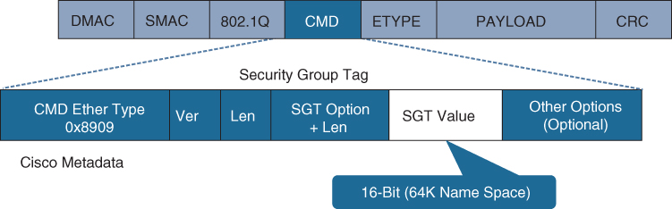
Figure 25-10 Layer 2 Ethernet Frame with an SGT Tag
_____________________: _____________________ is a _____________________ used for network devices that do not support _____________________ in hardware. Using_____________________, IP-to-SGT mappings can be communicated between _____________________switches and other network devices. _____________________ switches also have an SGT mapping database to check packets against and enforce policy. The _____________________ peer that sends IP-to-SGT bindings is called a speaker. The IP-to-SGT binding receiver is called a listener. _____________________ can be single-hop or multi-hop, as shown in Figure 25-11.
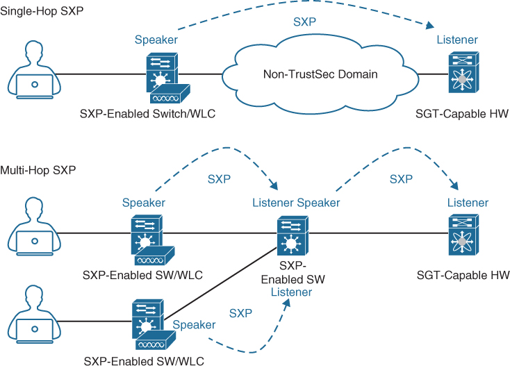
Figure 25-11 Single-Hop and Multi-Hop SXP Connections
Chapter 26
While many different kinds of ACLs can be used for packet filtering, only the following types are covered in this chapter:
Numbered standard ACLs: These ACLs define packets based solely on the source network, and they use the numbered entries ________________ and _________________.
Numbered extended ACLs: These ACLs define packets based on source, destination, protocol, port, or a combination of other packet attributes, and they use the numbered entries ________________ and ________________.
_____________________: These ACLs allow standard and extended ACLs to be given names instead of numbers and are generally preferred because they can provide more relevance to the functionality of the ACL.
_____________________: These ACLs can use standard, extended, named, and named extended MAC ACLs to filter traffic on Layer 2 switchports.
_____________________: These ACLs can use standard, extended, named, and named extended MAC ACLs to filter traffic on VLANs.
The Cisco IOS CLI by default includes three privilege levels, each of which defines what commands are available to a user:
_____________________: Includes the disable, enable, exit, help, and logoutcommands.
_____________________: Also known as _____________________ mode. The command prompt in this mode includes a greater-than sign (R1>). From this mode it is not possible to make configuration changes; in other words, the command configure terminal is not available.
_____________________: Also known as _____________________ mode. This is the highest privilege level, where all CLI commands are available. The command prompt in this mode includes a hash sign (R1#).
AAA is an architectural framework for enabling a set of three independent security functions:
_____________________: Enables a user to be identified and verified prior to being granted access to a network device and/or network services.
_____________________: Defines the access privileges and restrictions to be enforced for an authenticated user.
_____________________: Provides the ability to track and log user access, including user identities, start and stop times, executed commands (that is, CLI commands), and so on. In other words, it maintains a security log of events.
Chapter 27
There are two types of hypervisors, as illustrated in Figure 27-2:
Type 1: ________________________________________________________________
________________________________________________________________
Type 2: ________________________________________________________________
________________________________________________________________
Cisco ENFV delivers a virtualized solution for network and application services for branch offices. It consists of four main components that are based on the ETSI NFV architectural framework:
_____________________: Cisco DNA Center provides the VNF management and NFV orchestration capabilities. It allows for easy automation of the deployment of virtualized network services, consisting of multiple VNFs.
_____________________: VNFs provide the desired virtual networking functions.
_____________________: An operating system that provides virtualization capabilities and facilitates the deployment and operation of VNFs and hardware components.
_____________________: x86-based compute resources that provide the CPU, memory, and storage required to deploy and operate VNFs and run applications.
Chapter 28
Table 28-3 HTTP Functions and Use Cases
HTTP Function |
Action |
Use Case |
|
Requests data from a destination |
Viewing a website |
|
Submits data to a specific destination |
Submitting login credentials |
|
Replaces data in a specific destination |
Updating an NTP server |
|
Appends data to a specific destination |
Adding an NTP server |
|
Removes data from a specific destination |
Removing an NTP server |
Table 28-4 CRUD Functions and Use Cases
CRUD Function |
Action |
Use Case |
|
Inserts data in a database or application |
Updating a customer’s home address in a database |
|
Retrieves data from a database or application |
Pulling up a customer’s home address from a database |
|
Modifies or replaces data in a database or application |
Changing a street address stored in a database |
|
Removes data from a database or application |
Removing a customer from a database |
Table 28-5 HTTP Status Codes
HTTP Status Code |
Result |
Common Reason for Response Code |
|
OK |
Using GET or POST to exchange data with an API |
|
Created |
Creating resources by using a REST API call |
|
Bad Request |
Request failed due to client-side issue |
|
Unauthorized |
Client not authenticated to access site or API call |
|
Forbidden |
Access not granted based on supplied credentials |
|
Not Found |
Page at HTTP URL location does not exist or is hidden |