CLI and ASDM Connection
There are two ways to configure a Cisco ASA: through the CLI, or through the ASDM.
Both the CLI and ASDM offer benefits for configuration, and people disagree as to the best method. The CLI versus GUI configuration argument has been around since the days of UNIX versus Windows. The CLI is fast, after you have mastered it, but the GUI is very intuitive and easier to configure, especially with the wizard quick-configuration options now available.
CLI
The CLI is the historic way in which all Cisco devices were configured. This is a command-based interface similar to a UNIX- or DOS-based operating system. Commands are typed through a terminal connection to the ASA, and these are then written to the configuration. The CLI is powerful and fast, but learning how to use the CLI is like learning another language.
You can either connect to the CLI through the console port using a console cable or by using Telnet or Secure Shell (SSH).
NOTE
Because Telnet is sent in clear text and SSH is an encrypted session, you should always use SSH to connect to any network device.
Using a console cable is called an out-of-band connection, and using Telnet or SSH is called an in-band connection.
When you initially connect to an ASA, you are greeted with the following prompt:
ciscoasa>
This is called unprivileged mode and is represented by the > after the hostname. Entering enable at this prompt places you into privileged EXEC mode, and you will see the following prompt:
ciscoasa#
From privileged EXEC mode, you can then enter the configuration mode to enter configuration commands into the ASA. The show and debug commands to monitor and troubleshoot the ASA are also entered in privileged EXEC mode.
ASDM
You access the ASDM through a web browser. ASDM is a Java-based application, so any modern browser that supports Java will suffice (for instance, Safari, Firefox, or Internet Explorer). The connection to ASDM is over SSL, so the configuration is always encrypted between the client and the ASA through the web browser.
Because you have to connect to ASDM through a browser interface, you must configure an IP address on the inside interface to enable you to connect your browser to it. The next section covers interface configuration in more depth.
In addition to setting the IP address, you must enter some other basic configuration commands via the CLI to the ASA to configure the initial connection to the ASDM.
NOTE
You can use the quick-configuration system to configure the initial parameters of the ASA to facilitate ASDM connection, but we are providing the basic configuration commands without using the quick configuration.
We will now run through the necessary commands on an ASA that has a blank configuration. The commands shown are the bare minimum to enable a connection to the ASDM.
Because this is an ASA with a blank configuration, the only way to connect is via the CLI using a serial connection.
The first step is to assign an IP address to the inside interface of the ASA. To enter these commands, you need to be in configuration mode on the ASA. We assume from this point forward that you are in configuration mode; the prompt shows which configuration mode is required:
ciscoasa#configuration terminal
ciscoasa(config)#interface vlan 1
ciscoasa(config-if)#ip address 192.168.1.254 255.255.255.0
Because this VLAN is going to be the inside network, we now have to name the VLAN interface as the inside interface:
Ciscoasa(config-if)#nameif inside
INFO: Security level for "inside" set to 100 by default.
NOTE
For these examples, the configuration from a Cisco ASA 5505 is used. The ASA 5505 has a built-in eight-port switch with no fixed interfaces. IP addresses on the ASA 5505 are configured to VLAN interfaces, and then the VLANs are assigned to the Ethernet interfaces. For other ASA models, the IP address is added straight to the corresponding Ethernet interface.
When the nameif command is entered, because the value is inside, the default security level of 100 is attributed to the VLAN interface.
VLAN1 is now configured as the inside interface with the IP address of 192.168.254.1/24. By default, all ports are in VLAN1, so we now need to tell the ASA 5505 which physical Ethernet port is the inside connection. In this example, we are using Ethernet0/1 as the inside interface, so we enter the following commands to bring up Ethernet0/1, because by default all ports are in an administrative shutdown mode:
ciscoasa(config)#interface ethernet0/1
ciscoasa(config-if)#no shutdown
Running a show interface for Ethernet0/1 now displays the following:
ciscoasa#show interface ethernet0/1
Interface Ethernet0/1 "", is up, line protocol is up
Hardware is 88E6095, BW 100 Mbps, DLY 100 usec
Auto-Duplex(Full-duplex), Auto-Speed(100 Mbps)
Available but not configured via nameif
MAC address 001b.53a0.4e91, MTU not set
IP address unassigned
16423 packets input, 1256399 bytes, 0 no buffer
Received 896 broadcasts, 0 runts, 0 giants
0 input errors, 0 CRC, 0 frame, 0 overrun, 0 ignored, 0 abort
0 L2 decode drops
0 switch ingress policy drops
6518 packets output, 5096677 bytes, 0 underruns
0 output errors, 0 collisions, 0 interface resets
0 babbles, 0 late collisions, 0 deferred
0 lost carrier, 0 no carrier
0 rate limit drops
0 switch egress policy drops
We can see that the interface is up. We should now be able to ping the inside interface of the ASA 5505 from a workstation connected to the 192.168.1.0/24 network and be able to ping workstations on the 192.168.1.0/24 network from the ASA 5505.
The next step is to configure a secure password on the ASA. We are about to provide access to the web-based administration interface of the ASA, so we want to ensure that it is protected and locked down with authentication.
We will set an enable password on the ASA:
ciscoasa(config)#enable password securepassword
The preceding line creates the enable password securepassword. Obviously, you would replace this with a very secure, strong password.
At this point, the interface is up and has a valid IP address configured. However, we must complete a couple more steps to facilitate a connection to the ASDM. Running a browser to https://192.168.1.254 at this point will return with a “Page Not Found” message.
The ASA has a built-in web server. This is what serves the ASDM to users requesting it through their browsers. By default, this web server is not enabled.
The internal web server in the ASA is enabled with the following command:
ciscoasa(config)#http server enable
This enables the HTTP server on the ASA, but if you tried a connection to the ASDM, you still would not be able to connect. This failure to connect results because the ASA operates in a closed policy, unlike the HTTPS server on a router. On the ASA, all connections to the HTTP server are denied by default, and you must enter a configuration command to specify the IP addresses that are allowed to access the ASDM. On a router, by default all IP addresses can connect to the HTTP server, and you must create an access list to restrict this access.
In this example, we want to allow the whole inside network access to the ASDM:
ciscoasa(config)#http 192.168.1.0 255.255.255.0 inside
The preceding command allows all hosts on the 192.168.1.0/24 network, which is located on the inside interface, access to the ASDM.
Connecting now with a web browser to https://192.168.1.254 will display the initial ASDM connection screen shown in Figure 7.
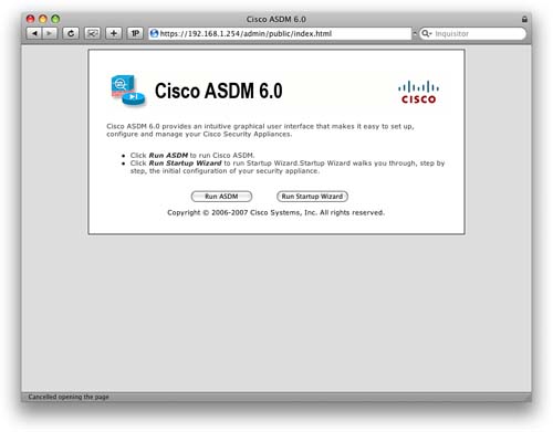
You can either run the ASDM or the Startup Wizard to take you through the initial setup of the ASA. We are going to click the Run ASDM button to launch ASDM.
The next window that appears asks for authentication (see Figure 8).
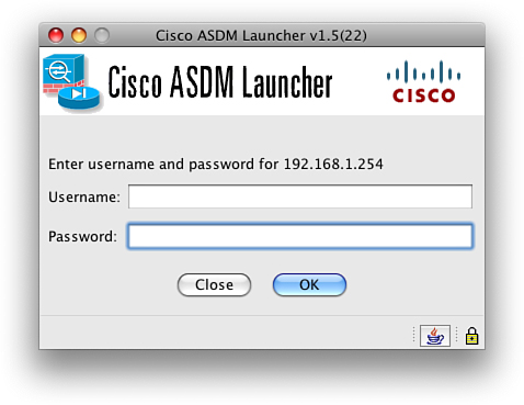
The authentication box requests a username and password. Because we have not configured any users on the system, we just need to enter the enable password into the Password field and leave the Username field blank.
NOTE
In a real-world situation, always ensure that you use a username and password combination for authentication to the ASA. Never rely on just the enable password for authentication.
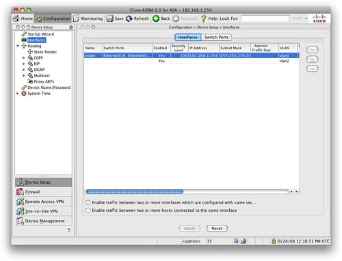
We are now presented with a connection to the ASDM (see Figure 9).
Interface Configuration Using CLI and ASDM
The ASA is a network device. Therefore, for it to function, you must configure the network interfaces. We look here at how to configure the interface parameters via both the CLI and ASDM.
The three aspects to configuring an interface on a Cisco ASA are as follows:
![]() IP address and subnet mask
IP address and subnet mask
![]() Interface name
Interface name
![]() Interface security level
Interface security level
IP Address and Subnet Mask
Each interface requires its own IP address that exists in a different subnet. The ASA can operate in two modes: routed and transparent. For these examples, we use routed mode (the default). Transparent mode is covered in Section 4 of this Quick Reference guide.
We have already applied an IP address of 192.168.1.254/24 to the inside interface of the ASA. We now configure the IP address of 10.0.0.1/24 to the outside interface. This setup follows the simple network diagram shown in Figure 10.
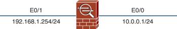
To assign an IP address to an interface, you use the ip address command from interface configuration mode. The following example sets the IP address of 10.0.0.1/24 to Ethernet0/0:
ciscoasa(config)#interface ethernet0/0
ciscoasa(config-if)#ip address 10.0.0.1 255.255.255.0
In our example, we are using an ASA 5505, and we assigned an IP address of 192.168.1.254/24 to the VLAN1 interface. The configuration command for this is as follows:
ciscoasa(config)#interface vlan1
ciscoasa(config-if)#ip address 192.168.1.254 255.255.255.0
Interface Name
All interfaces on an ASA must be given a name. These names are used in other configuration items, such as Network Address Translation (NAT) and access control lists (ACLs). Some common names include outside, inside, and DMZ. It is worthwhile to provide a meaningful name.
To give Ethernet0/1 the name of inside, we issue the following command:
ciscoasa(config)#interface ethernet0/1
ciscoasa(config-if)#nameif inside
In our example, we are using an ASA 5505, and we assigned the name of inside to the VLAN1 interface. The configuration command for this is as follows:
ciscoasa(config)#interface vlan1
ciscoasa(config-if)#nameif inside
Interface Security Level
The ASA in its default state uses interface security levels to determine traffic flow and to ascertain what action the appliance should take on traffic traversing it. Every interface must have a security level. This originated from a PIX technology called the Adaptive Security Algorithm (confusingly, also ASA).
The two important factors are as follows:
![]() Traffic from a higher-security interface to a lower-security interface is by default allowed. This is classed as outbound traffic. Configuration is required to allow the traffic, but it will flow without the use of ACLs.
Traffic from a higher-security interface to a lower-security interface is by default allowed. This is classed as outbound traffic. Configuration is required to allow the traffic, but it will flow without the use of ACLs.
![]() Traffic from a lower-security interface to a higher-security interface is by default disallowed. This is classed as inbound traffic. The use of ACLs is required to allow inbound traffic.
Traffic from a lower-security interface to a higher-security interface is by default disallowed. This is classed as inbound traffic. The use of ACLs is required to allow inbound traffic.
Some default security levels are assigned to interfaces. By default, the outside interface always has a security level of 0, and the inside interface has a security level of 100.
The minimum level is 0, and the maximum level is 100. Therefore, these two interfaces are placed at either end of the scale and thus allow additional interfaces, such as the DMZ, to be placed between these values to further enhance the security design of the network. It is common for a DMZ interface to be assigned a security level of 50.
To give Ethernet0/1 the security level of 100, we issue the following command:
ciscoasa(config)#interface ethernet0/1
ciscoasa(config-if)#security-level 100
In our example, we are using an ASA 5505, and we assigned the name of inside to the VLAN1 interface. This configuration means that this interface will have a security level of 100. The configuration command for this is as follows:
ciscoasa(config)#interface vlan1
ciscoasa(config-if)#security-level 100
ASDM Interface Configuration
You can configure an interface via ASDM from a single configuration screen.
You must select Configuration from the toolbar, and then Device Setup. You can then add, edit, or delete interfaces from the configuration.
Because we have already configured the inside interface in our example as VLAN1, we will now enhance this by only configuring VLAN1 on the Ethernet0/1 physical port.
We highlight the inside interface and then click Edit. Figure 11 shows the Edit Interface screen.
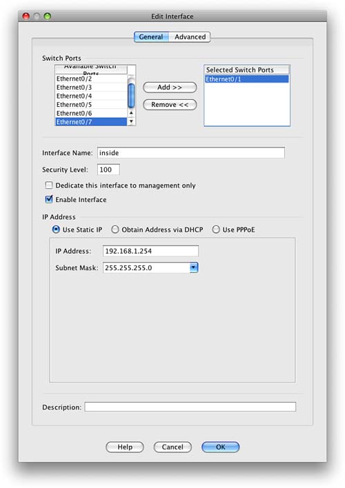
As you can see from Figure 11, the IP address, interface name, and security level can all be entered into the ASA configuration from this single screen. In this example, you can see that Ethernet0/1 has been selected and has an IP address of 192.168.1.254/24, with an interface name of inside and a security level of 100.
No firewall is complete with a single interface, so let’s go ahead and configure the outside interface of the ASA.
Figure 12 shows the configuration screen on the ASA for the outside interface.
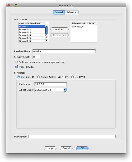
You can see in Figure 12 that we have assigned Ethernet0/0 an IP address of 10.0.0.1/24. We have named this interface outside and given it a default security level of 0.
We now have the network as shown in Figure 13.
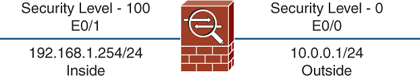
Now the interfaces are configured, let’s move on and look at the other areas of initial configuration required to get the ASA functioning.
Network Address Translation
Network Address Translation (NAT) is a key concept and technology used by the ASA. The main purpose of NAT is to translate one IP address into another. It is commonly used to translate private RFC 1918 IP addresses into publicly routable IP addresses for use over the Internet.
Figure 14 shows how NAT would be used in the simple network we have configured on the ASA.
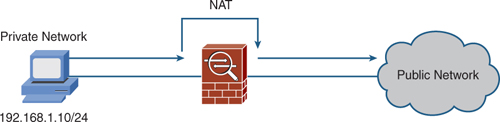
NAT, in the true sense, translates one address to another address. There is also another technology called Port Address Translation (PAT). PAT is where multiple internal addresses are translated into a single external address. Different source ports are used on the external address to differentiate between the internal addresses, and this information is held by the device performing the translation so that it can work out where to send the return packets. PAT is also called NAT-Overload.
On the ASA, NAT is required when traffic is flowing from a lower-security interface to a higher-security interface. For example, the outside interface has a security level of 0, and the inside interface has a security level of 100. Therefore, NAT is required for hosts on the outside to communicate with hosts on the inside.
NAT is not required by default for traffic flowing from a higher-security interface to a lower-security interface. This has been the case since Cisco released PIX and ASA 7.0. You can enable this setting by issuing the nat-control command, which then forces NAT on all interfaces in all directions.
Simple NAT Configuration
To configure NAT on the ASDM, choose Configuration from the toolbar and then Firewall. NAT rules are created on the ASA and perform the translations depending on the configuration. By default, no NAT rules are configured on the ASA.
You can add three main types of NAT rules: static NAT rules, dynamic NAT rules, and NAT exempt rules.
We can start by adding a static NAT rule.
Adding a Static NAT Rule with ASDM
Static NAT is where you are performing a one-to-one NAT translation; a single internal IP address is translated to a single external IP address. This is normally used for inbound access where external users are accessing resources such as a corporate web or email server.
Figure 15 shows the inclusion of a web server in our simple network topology.
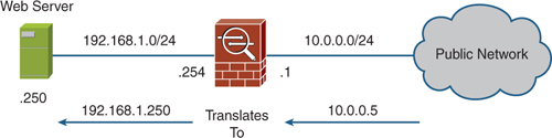
The web server has an internal IP address of 192.168.1.250/24. Hosts from the outside cannot access this server on this address, because it is not routable via the outside interface (because a NAT translation is required).
What we need to configure is a static NAT entry from 192.168.1.250 that translates to 10.0.0.5. Doing so then enables external users to access the web server on 10.0.0.5.
We have chosen to add a static NAT translation and then entered the settings as shown in Figure 16.
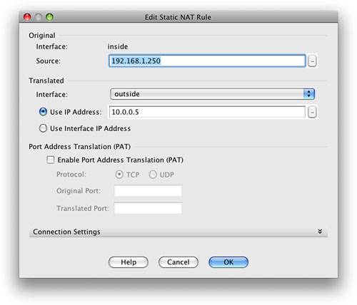
You can see in Figure 16 that we have entered the original and translated addresses into the ASDM. This setting will translate 192.168.1.250 to 10.0.0.5 on the outside interface. When we apply this setting, we are then taken back to the NAT Rules configuration screen that is shown in Figure 17.
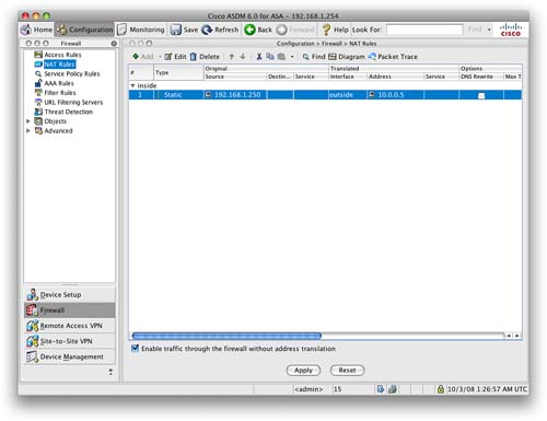
This screen lists all the configured NAT rules on the ASA, which in this case is only the single static NAT rule.
Now that we have configured a static NAT rule through the ASDM, the next rule to look at is a dynamic NAT rule.
Adding a Dynamic NAT Rule with ASDM
Static NAT translations provide a one-to-one translation of IP addresses. A dynamic NAT rule creates a one-to-many translation of IP addresses.
The most common use of dynamic NAT is when the ASA is placed at the network perimeter between the corporate network and the Internet. Users on the corporate network want Internet access, so they require a NAT translation to translate their private IP address to a publicly routable IP address. If there are 50 internal users, you require 50 public addresses for the translation.
Dynamic NAT uses a single public IP address and allows all the internal users access to the Internet. They all use the same public IP address, and they are tracked by the ASA by using different source ports for each internal client.
When we add a dynamic NAT rule, we have to link it to an address pool. You can create these address pools via Objects > Global Pool, or you can create them while adding the dynamic NAT rule.
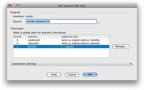
You can see from Figure 18 that we have created a dynamic NAT rule that applies to 192.168.1.0/24 and uses the address of the outside interface for the translation.
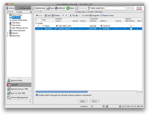
When we apply this rule, we are taken back to the NAT Rules screen. We can now see on this screen, as shown in Figure 19, that there is a configured static NAT rule and a dynamic NAT rule.
The last type of NAT rule that we are going to look at is a NAT exempt rule.
Adding a NAT Exempt Rule with ASDM
We have just configured static and dynamic NAT on the ASA via ASDM. We will now look at the third option available when adding a NAT rule, a NAT exempt rule.
NAT exemption exempts addresses from NAT translation. When NAT is configured on an interface, you sometimes might need a specific host to bypass NAT and be exempt from the NAT rules. A common use of this is when configuring VPNs and you want the local private network to be able to communicate with the remote private network without being translated.
Access Lists
We have just looked at configuring NAT on the ASA. Now that you have configured NAT, the next element to look at is ACLs.
ACLs are the restrictive lists that define a firewall. These can be also be called a firewall rule set or rule base. The ACL is one of the most important aspects of the firewall because it permits and denies traffic through the firewall. The incorrect configuration of an ACL can result in a security hole that a potential attacker may use to exploit an internal system.
Configuring ACLs with ASDM
In our example, we have shown a web server on the inside of the network. This web server has a static NAT translation. We are now going to provide an ACL that allows inbound traffic matching the web server address to access the web server.
To configure ACLs, select Configuration from the toolbar and then Firewall > Access Rules.
You will see that by default some rules are already applied to the ASA. These are the implicit rules configured by default on the ASA device. These rules cannot be removed; they are the catchall rules that are matched if no other rule is matched first.
Figure 20 shows these implicit rules.
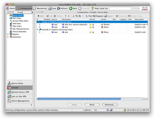
Looking at Figure 20, we can see that there are three implicit access rules. Two are applied to the inside interface and one to the outside interface.
The implicit access rules applied to the inside interface are as follows:
![]() Permit traffic from anywhere destined to a lower-security interface
Permit traffic from anywhere destined to a lower-security interface
![]() Deny any traffic from anywhere to anywhere
Deny any traffic from anywhere to anywhere
This rule implements the Adaptive Security Algorithm (ASA) mentioned earlier. Any traffic from the inside interface is permitted only to lower-security interfaces. All other traffic is denied.
The implicit access rule applied to the outside interface is as follows:
![]() Deny any traffic from anywhere to anywhere
Deny any traffic from anywhere to anywhere
Because the outside interface has the lowest available security level (0), all traffic is by default denied unless a more specific access rule permits it. This default ensures that nothing enters the firewall from the outside without previous configuration.
Clicking Add brings up the Add an Access Rule screen. We want to add a rule on the outside interface to allow access to the internal web server on TCP port 80.
Figure 21 shows the completed screen to create this access rule.
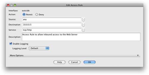
You can see from Figure 21 that we have created a rule that permits TCP port 80/HTTP traffic from anywhere to access the outside interface and the address 10.0.0.5. This is the address that we used for the static NAT translation for the web server.
Applying this access rule takes us back to the Access Rules screen of the ASDM, as shown in Figure 22.
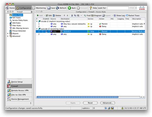
You can now see the new rule that has been configured on the outside interface and has been placed above the implicit rule that denies all other traffic.
Traffic can now access the website from anywhere on the Internet.
Using Object Groups Within ACLs
We now want to extend this further and permit HTTPS into the web server. We also want to use the name webserver-public rather than the public IP address of the web server.
We can achieve both of these goals by configuring objects on the ASA.
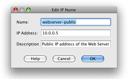
Let’s start by defining the web server as an object within the ASA. Navigate to Firewall > Objects > IP Names. Add an entry using the public IP address of the web server and the name of webserver-public. You can see this completed in Figure 23.
We have now configured a more meaningful name for the public IP address of the web server. Next we want to configure an access rule to also allow HTTPS access to the web server.
We could just add another access rule that permits HTTPS from anywhere to the web server, as we did with the initial access rule that permitted HTTP. However, we are going to achieve this is by creating a service group. Navigate to Firewall > Objects > Service Groups, and then click Add to add a new service group.
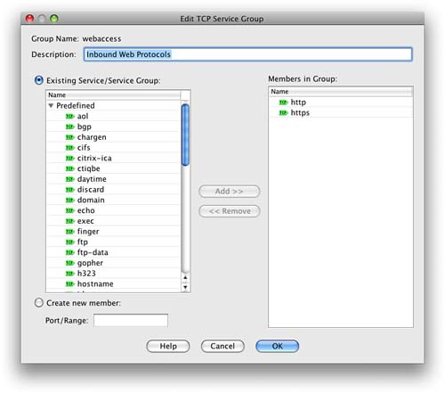
Because both HTTP and HTTPS are TCP protocols, we need to select TCP Service Group. Let’s call the group webaccess and let’s add both HTTP and HTTPS to the group.
Figure 24 shows that we have created a single TCP service group that now contains two protocols.
The next step is to go back to the Access Rules configuration screen and change the existing access rule to use the new group.
When we navigate to Firewall > Access Rules, note that the Destination field for the access rule that we created has now changed from 10.0.0.5 to webserver-public. This is because we have added the IP name object for the web server. From now on, the ASA will know 10.0.0.5 as webserver-public, making it easier to read the rule base and understand it.
Highlight the rule we created earlier and click Edit. Select the service by clicking the ellipsis (...) button next to the service. We now need to add the TCP service group that we have just created. The service group should be at the top of the list. Select it and click OK to return to the main Access Rules screen, as shown in Figure 25.
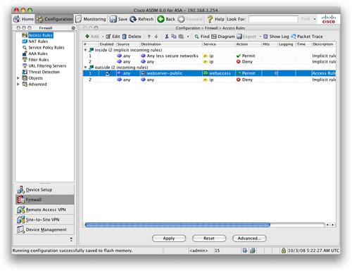
Looking at Figure 25, we can see that the destination name is now webserver-public and the service is now webaccess and not HTTP.
We have just created a single rule that allows both HTTP and HTTPS access inbound on the outside interface to the public address of the web server.
Routing
The ASA supports both static and dynamic routing. The ASA supports the Routing Information Protocol (RIP), Open Shortest Path First (OSPF) Protocol, and Enhanced Interior Gateway Routing Protocol (EIGRP).
Configure a Static Default Route on the ASA
One of the commonly used routes on the ASA will always be the static default route. This is the destination of last resort and where all packets are sent that do not match a more specific route on the ASA.
A high percentage of ASAs are deployed at the network perimeter, normally acting as the firewall between the corporate network and the public Internet. In these cases, a static default route will always be used that points out to the Internet.
To configure a static default route, select Configuration from the ASDM toolbar and then Device Setup. One of the options now presented is Routing. The first option configures static routes.
Click Add to add a static route. Figure 26 shows a default static route that we have entered that will send traffic to the next hop from the ASA out to the public Internet.

You can see from Figure 26 that we have set a route to 0.0.0.0 0.0.0.0 that points to 10.0.0.2. The notation of 0.0.0.0 0.0.0.0 is the default catchall address, which can also be represented as 0 0.
Configure Passive RIP on the ASA
RIP can be configured on the ASA. The ASA supports both RIPv1 and RIPv2. Earlier security devices such as the PIX would only operate in passive mode, in which the interfaces configured for RIP would only accept routes and not propagate routing information from the device. The ASA allows the device to participate in full RIP routing.
For this example, we configure passive RIP on the ASA, which is a requirement of the SNAF exam.
RIP configuration is performed from the RIP section of the Routing navigation which is located under Configuration>Device Setup. The first step is to enable RIP on the ASA. Figure 27 shows the configuration required for passive RIP.
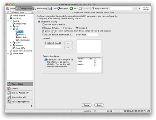
Figure 27 shows that we have enabled RIP, set it to use RIPv2, and globally set all interfaces to be passive. This setup means that the ASA will listen and accept routes learned via RIP but will not advertise any of its own routes out to adjacent RIP neighbors.
Switching
The ASA allows you to configure multiple logical interfaces that are connected to a single physical interface. Therefore, you can assign the logical interfaces to specific VLANs. The logical interfaces are called subinterfaces. You can assign only a single VLAN to a subinterface. Each subinterface must have a VLAN ID before it can pass traffic. Because VLANs allow you to keep traffic separate on a given physical interface, you can increase the number of interfaces available to your network without adding additional physical interfaces or security appliances. Therefore, you can use the ASA in areas that require more interfaces than exist on the installed ASA.
When a physical interface is split into subinterfaces, the physical interface becomes an 802.1Q trunk. This is the same concept as when a switch port on a Cisco Catalyst switch is configured as a trunk to pass VLAN traffic between switches.
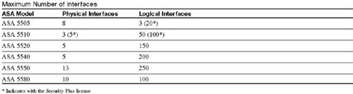
The following table shows the maximum number of physical and logical interfaces that you may configure per ASA model.
NOTE
You cannot configure subinterfaces on the ASA 5505 because it is a switch-based appliance where the eight physical interfaces are part of the switch and must be assigned to a VLAN interface.
To configure a logical interface, you must add an interface from the Add Interface screen (see Figure 28).
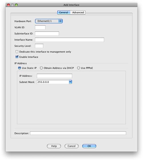
You can then select which interface this subinterface is to be bound to and set the options such as the VLAN ID and subinterface ID to configure the subinterface.