Modular Policy Framework
The Modular Policy Framework (MPF) is an advanced feature of the ASA that provides the security administrator with greater granularity and more flexibility when configuring network policies. The security administrator is able to do the following:
![]() Define flows of traffic
Define flows of traffic
![]() Associate security policies to traffic flows
Associate security policies to traffic flows
![]() Enable a set of security policies on an interface or globally
Enable a set of security policies on an interface or globally
Modular policies consist of the following components:
![]() Class maps
Class maps
![]() Policy maps
Policy maps
![]() Service policies
Service policies
Class Maps
A class map is a configuration element that is used to match something. A class map is similar in operation to an access control list (ACL), but with class maps you can match other items that ACLs cannot match.
Class maps can define a class of traffic by matching via the follow command keywords:
![]() access list:An entry in an ACL.
access list:An entry in an ACL.
![]() any:Any packet.
any:Any packet.
![]() default inspection traffic:The default TCP and UDP ports used by all applications that the security appliance can inspect. You can specify an ACL-based class along with the default inspection traffic class to narrow the matched traffic.
default inspection traffic:The default TCP and UDP ports used by all applications that the security appliance can inspect. You can specify an ACL-based class along with the default inspection traffic class to narrow the matched traffic.
![]() dscp:A differentiated services code point (DSCP) value in the IP header defined by the Internet Engineering Task Force (IETF).
dscp:A differentiated services code point (DSCP) value in the IP header defined by the Internet Engineering Task Force (IETF).
![]() flow:All traffic going to a unique IP destination address.
flow:All traffic going to a unique IP destination address.
![]() port:Traffic using the TCP or UDP destination port or a contiguous range of ports.
port:Traffic using the TCP or UDP destination port or a contiguous range of ports.
![]() precedence:The precedence value represented by the Type of Service (ToS) byte in the IP header.
precedence:The precedence value represented by the Type of Service (ToS) byte in the IP header.
![]() rtp:Real-Time Transport Protocol (RTP) destination port.
rtp:Real-Time Transport Protocol (RTP) destination port.
![]() tunnel-group:VPN tunnel traffic. If you use this criterion, you can also configure the class to match a specific destination IP address within the tunnel group.
tunnel-group:VPN tunnel traffic. If you use this criterion, you can also configure the class to match a specific destination IP address within the tunnel group.
Class maps are assigned to policy maps.
Policy Maps
Class maps are assigned to policy maps. The class map determines what is matched, and the policy map associates one or more actions with a class of traffic.
The policy actions that can be configured are as follows:
![]() Forward the traffic flow to the Security Services Module (when present) for intrusion protection or content security and control services by creating an intrusion prevention system (IPS) or a content security and control (CSC) policy.
Forward the traffic flow to the Security Services Module (when present) for intrusion protection or content security and control services by creating an intrusion prevention system (IPS) or a content security and control (CSC) policy.
![]() Perform a specified protocol inspection or inspections by creating an inspection policy.
Perform a specified protocol inspection or inspections by creating an inspection policy.
![]() Police the bandwidth used by the specified flow by creating a quality of service (QoS) police policy.
Police the bandwidth used by the specified flow by creating a quality of service (QoS) police policy.
![]() Direct the flow to the low-latency queue by creating a QoS priority policy.
Direct the flow to the low-latency queue by creating a QoS priority policy.
![]() Set connection parameters on the flows by creating a set connection policy.
Set connection parameters on the flows by creating a set connection policy.
Service Policies
The service policy activates a policy map on a targeted interface or globally on all interfaces. Service policies are represented as service policy rules in the ASDM.
To configure a service policy rule, you first need to navigate to Firewall > Service Policy Rules. You will see a screen that shows the default service policy rule (see Figure 39).
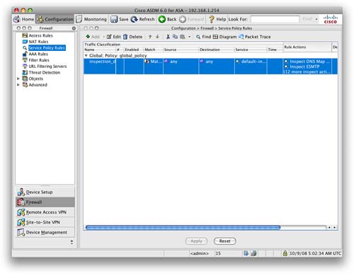
Clicking Add launches the Add Service Policy Rule Wizard. Three steps to this wizard configure a service policy rule:
Step 1: Configure a service policy.
Step 2: Configure the traffic classification criteria for the service policy rule.
Step 3: Configure actions on the traffic classified by the service policy rule.
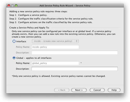
Step 1: Configure a Service Policy
In Step 1, you have to give the service policy a name and either apply it to a specific interface or apply it globally, which applies the policy on all interfaces. You can also provide a description of the service policy. You can see the screen in Figure 40.
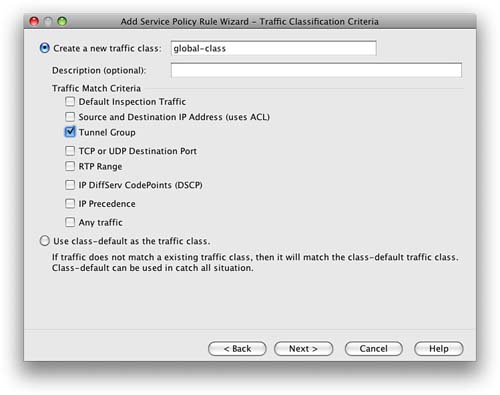
Step 2: Configure the Traffic Classification Criteria for the Service Policy Rule
You are now asked to either create a new traffic class or use an existing traffic class.
When creating a new traffic class, you must enter the name for the new traffic class and supply a description. You have the option to match traffic against the criteria we covered earlier in this section about class maps.
This is shown in Figure 41.
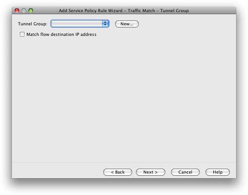
When you select one of the traffic-match criteria, the next screen you are shown is the configuration screen for that criteria. We chose Tunnel Group as the traffic-match criteria, and Figure 42 shows that you have the option now to select a tunnel group to match.
Step 3: Configure Actions on the Traffic Classified by the Service Policy Rule
The next screen is the Rule Actions screen. Three tabs display at the top of the screen:
![]() Protocol Inspection
Protocol Inspection
![]() Connection Settings
Connection Settings
![]() QoS
QoS
The Protocols Inspection tab enables you to configure protocol-specific inspections if the traffic-match criteria allow it. Figure 43 shows this screen.

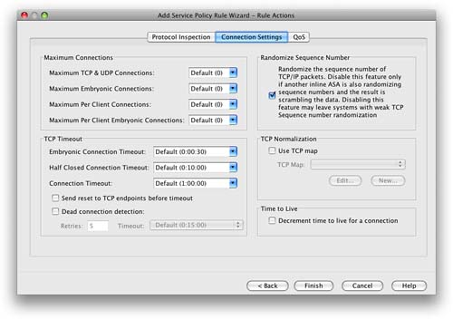
The Connection Settings tab enables you to set the maximum connections for TCP and UDP connections and the TCP timeout. You can also choose to randomize the TCP sequence number and enable TCP normalization.
Figure 44 shows this screen.
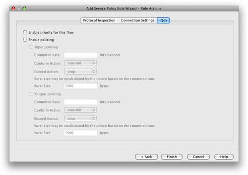
You can use the QoS tab to enable priority and policing for the traffic flow. When policing is selected, you can apply QoS settings to the flow to restrict the amount of bandwidth the flow is provided when traversing the interfaces of the firewall.
You can use this setting to reduce potential denial-of-service (DoS) attempts, because you can limit the amount of bandwidth allocated to a protocol.
Figure 45 shows this screen.
You click Finish to apply the service policy rule. It is added to the ASA when you click Apply from the main Service Policy Rules window on the ASDM.
Threat Detection
Threat detection on the ASA is similar in operation to an IPS.
Two types of threat detection are available on the ASA:
![]() Basic threat detection
Basic threat detection
![]() Scanning threat detection
Scanning threat detection
Basic threat detection is enabled by default. You can enable both basic and scanning threat detection independently of each other. One is not dependent on the other, and therefore you can have one, both, or neither configured on your ASA.
Basic Threat Detection
The security appliance basic threat detection feature provides threat-related drop statistics by monitoring the rate of dropped packets and security events per second (eps).
Note
Basic threat detection is enabled by default on the ASA. There is a minimal impact on performance when there are drops or potential threats on the ASA.
When the rate of dropped packets or security events exceeds established thresholds, basic threat detection generates a syslog message.
This enables you to detect activity that might be related to an attack, such as a DoS attack.
The ASA basic threat detection provides threat-related drop statistics by monitoring the following events:
![]() Access list denials
Access list denials
![]() Bad packet format
Bad packet format
![]() Exceeded connection limits
Exceeded connection limits
![]() Detection of DoS attacks
Detection of DoS attacks
![]() Failed basic firewall checks
Failed basic firewall checks
![]() Detection of suspicious Internet Control Message Protocol (ICMP) packets
Detection of suspicious Internet Control Message Protocol (ICMP) packets
![]() Packets failing application inspection
Packets failing application inspection
![]() Interface overload
Interface overload
![]() Detection of scanning attacks
Detection of scanning attacks
![]() Detection of incomplete sessions, such as TCP SYN attacks or no data UDP session attacks
Detection of incomplete sessions, such as TCP SYN attacks or no data UDP session attacks
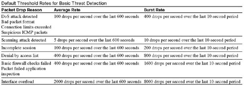
The ASA tracks two types of rates for each monitored events: the average rate and burst rate.
The average rate is the average rate over a time interval, and the burst rate is the one-tenth of the average rate or 10 seconds, whichever is the highest.
Syslog messages are generated when either of the rates for the monitored events is exceeded.
The following table shows the default threshold rates for basic threat detection.
Basic threat detection is configured from the Firewall > Threat Detection screen. This is shown in Figure 46.
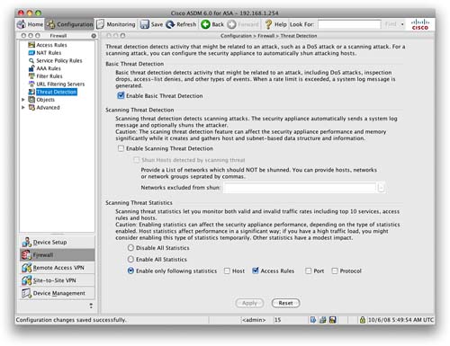
You can see from Figure 46 that basic threat detection is enabled on this ASA. To disable it, uncheck the check box.
Tuning of the basic threat detection is performed in the CLI configuration with the threat-detection command. This is beyond the scope of the SNAF exam.
Scanning Threat Detection
The scanning threat detection feature of the ASA is concerned with hosts performing network scans against networks protected by the ASA.
Network reconnaissance scans, or port scans as they are commonly known, are normally a precursor to an attacker launching a full-blown attack on a system. The first step is normally to identify which ports and services are available on a system before enumerating and fingerprinting these ports to check for known vulnerabilities. A known vulnerability is always the preferred route in for attackers because they can use simple attack scripts to gain access and then escalate privileges.
Note
The scanning threat detection feature can significantly affect the performance and memory use of the ASA while it creates and gathers the host- and subnet-based data structure and information. Performance impact varies depending on the ASA platform.
When performing scanning threat detection, the ASA utilizes an extensive database of host statistics to generate syslog messages when a host is identified as either an attacker, or a target.
As with basic threat detection, scanning threat detection is configured from the Firewall > Threat Detection screen.
We have now enabled scanning threat detection and selected to shun hosts detected by scanning threat.
Figure 47 shows the Threat Detection configuration window with both basic threat detection and scanning threat detection enabled.
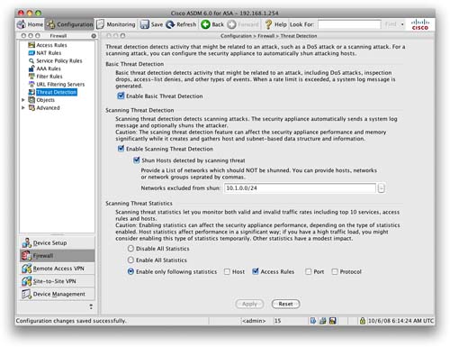
When a shun is activated, all current connections from the malicious host are dropped, and all future connections are blocked at the outside interface of the ASA. Shuns are dynamic in nature, and are not stored as a part of the configuration. If the security appliance loses power or reloads, any active shuns are lost.
You can specify a network, or network object, that will not be shunned. In the example, we have set that 10.1.0.0/24 will not be shunned. This setting is useful for entering networks that should never be blocked, such as testing partners or third-party support organizations.
Transparent Firewalling
In Section 2, we mentioned the two modes of operation for the Cisco ASA: routed and transparent.
Routed mode is the default mode, and this is where the ASA acts as a Layer 3 device, requiring an IP address on each interface that is from a different Layer 3 subnet. The ASA operates like a router.
Transparent mode is where the ASA acts like a Layer 2 bridge. The ASA is based on MAC addresses, and it will no longer sit on the perimeter between subnets; instead, it will act as a transparent bridge. An ASA running in transparent mode differs from routed mode in the following ways:
![]() Supports only two interfaces
Supports only two interfaces
![]() Requires only one IP address
Requires only one IP address
![]() Bridges packets from one interface/VLAN to the other
Bridges packets from one interface/VLAN to the other
![]() Performs MAC address lookups rather than routing table lookups
Performs MAC address lookups rather than routing table lookups
![]() Can pass traffic that cannot be passed by a security appliance in routed mode
Can pass traffic that cannot be passed by a security appliance in routed mode
The following are limitations that you must consider when implementing an ASA in transparent mode:
![]() Dynamic DNS is not supported.
Dynamic DNS is not supported.
![]() Dynamic routing protocols are not supported.
Dynamic routing protocols are not supported.
![]() IPv6 is not supported.
IPv6 is not supported.
![]() DHCP Relay is not supported.
DHCP Relay is not supported.
![]() QoS is not supported.
QoS is not supported.
![]() Multicast is not supported.
Multicast is not supported.
![]() Virtual private network (VPN) termination is not supported.
Virtual private network (VPN) termination is not supported.
One of the main advantages of using an ASA in transparent mode is that you can place the ASA in the network without re-addressing. This makes the firewall a viable solution where the infrastructure already exists and re-addressing would prove troublesome.
We will now look at how to configure the ASA as a transparent firewall using both the CLI and the ASDM.
Transparent Firewall Configuration: CLI
From the command line, you can verify what the current firewall mode is with the show firewall command:
ciscoasa#show firewall
Firewall mode: Router
This shows that the current firewall is in routed mode. We can switch the ASA to transparent mode with the following command:
ciscoasa(config)#firewall transparent
NOTE
When switching modes between routed and transparent, the ASA will clear the configuration. Therefore, it is important that you have a backup of the current configuration. The ASA provides no warning or no confirmation, so this command can be very dangerous if used incorrectly. So, you should also change the mode while connected via the console cable. A Secure Shell (SSH) or Telnet connection to the ASA will result in a loss of connection if the firewall mode is changed.
Checking the current firewall mode now shows the following:
ciscoasa#show firewall
Firewall mode: Transparent
The ASA is now in transparent mode. If you now check the running configuration, you will see that all the interfaces will be in a shutdown state, with the entire VLAN, interface, and IP configuration that we have previously entered absent.
The first configuration step with transparent mode is to assign the management IP address. Because the ASA does not now participate in IP routing, we have to give the ASA an IP address so that we can access it via SSH and the ASDM for management.
Let’s use the same IP address as before, 192.168.1.254, but this time it will be as the management IP address. We configure this with the following command.
ciscoasa(config)#ip address 192.168.1.254 255.255.255.0
This sets the management IP address to be 192.168.1.254/24. We can use the show ip address command to verify this:
ciscoasa#show ip address
Management System IP Address:
ip address 192.168.1.254 255.255.255.0
Management Current IP Address:
ip address 192.168.1.254 255.255.255.0
We now need to configure the two interfaces that we are going to use with the ASA. For ease of use, we will call these the default inside and outside interfaces, as covered in Section 2.
Note that although the inside and outside interfaces are on the same subnet, they have to be on different VLANs; otherwise, the ASA will not pass traffic. Figure 48 shows the change to the topology that we are using so that the ASA in our example will be used in transparent mode.

We now have to follow the steps outlined in Section 2 to set up the ASA so that we can access ASDM. In brief, we need to enable and configure an interface and enable the HTTP server on the ASA. When that is completed, you will be able to connect to the ASDM using the 192.168.1.254 management address that we configured.
Figure 49 shows us connected again to the ASDM. Notice that the firewall mode is shown as transparent.

We are now going to configure the transparent firewall in ADSM.
If you need to switch back to router mode, you must use the no firewall transparent command to return to the original routed mode of the ASA:
ciscoasa(config)#no firewall transparent
Checking the current firewall mode now shows the following:
ciscoasa#show firewall
Firewall mode: Router
Transparent Firewall Configuration: ASDM
Once you are connected to the ASDM, you will notice that some of the configuration options available when the ASA was in routed mode are not available any more. When the ASA is in transparent mode, there is limited functionality and new functionality such as the ability to create Ethertype rules.
Adding an access rule on a transparent firewall is the same as adding an access rule on a routed firewall. You do it from the Firewall > Access Rules screen, and the format is the same for a transparent ASA as for a routed ASA.
Figure 50 shows the default access rules for the ASA in transparent mode.
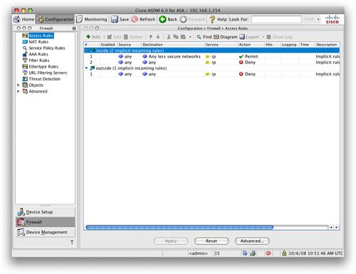
Note that these default rules are the same as with a routed ASA. Therefore, the Adaptive Security Algorithm still applies to the security level, allowing traffic only to flow in one direction by default (without the addition of access rules to permit it).
We are now going to look at two functions that you can perform with the ASA in transparent mode that you cannot do in routed mode. These are permitting multicast and broadcast traffic through the ASA and configuring an Ethertype ACL.
Permitting Multicast and Broadcast Traffic
Because the ASA is now operating as a bridge, it is possible to pass multicast and broadcast traffic through it. This is good for passing traffic such as dynamic routing protocols, DHCP, and multicast streams, all of which cannot pass through a traditional routed ASA.
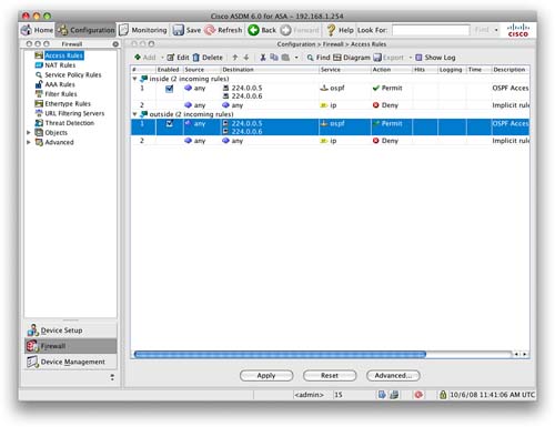
Let’s create an access rule to permit Open Shortest Path First (OSPF) Protocol traffic through the ASA in both directions. OSPF uses multicast addresses to communicate with its neighbors and to send routing updates. Figure 51 shows an access rule that will allow any traffic destined for the multicast address 224.0.0.5 or 224.0.0.6.
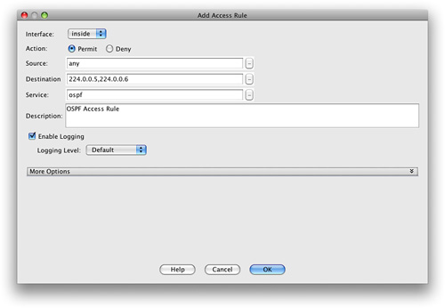
We then create a rule on the outside interface to allow OSPF to be allowed from the outside in. When this is applied, we are presented with the Access Rules screen, as shown in Figure 52.
Configuring an Ethertype ACL
When the Cisco ASA is in transparent mode, it can also allow non-IP traffic through the firewall, something that the ASA in routed mode would not be able to do. This is achieved by creating what is called an Ethertype ACL.
Layer 2 traffic has an Ethertype that can be seen in the Layer 2 headers of the frame. These Ethertypes are assigned by the Internet Assigned Numbers Authority (IANA), and the list of assigned Ethertypes can be downloaded from http://www.iana.org/assignments/ethernet-numbers.
To configure an Ethertype rule, navigate to Firewall > Ethertype Rules. From here, you can add a new rule.
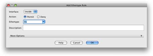
Figure 53 shows the Add Ethertype Rule window. From here, you can select the interface, action, and Ethertype to permit or deny.
The common supported Ethertypes on the ASA are as follows:
![]() BPDU
BPDU
![]() IPX
IPX
![]() MPLS-Multicast
MPLS-Multicast
![]() MPLS-Unicast
MPLS-Unicast
In addition to these built-in Ethertypes, you can enter any value for any Ethertype, as outlined in the IANA Ethertype assignments. The value has to be entered in hexadecimal format. For example, ARP would be 0x0806.
Verifying the Transparent Firewall
From the CLI, you can use a few commands to verify the transparent firewall. Some of the main ones are listed here:
![]() show firewall:Displays the mode the firewall is in.
show firewall:Displays the mode the firewall is in.
![]() show access-list:Displays the currently configured access lists.
show access-list:Displays the currently configured access lists.
![]() show mac-address-table:Displays the bridging MAC address table.
show mac-address-table:Displays the bridging MAC address table.
![]() show arp:Displays the Address Resolution Protocol (ARP) table of the ASA.
show arp:Displays the Address Resolution Protocol (ARP) table of the ASA.