Telnet and SSH Access to the ASA
We have already connected to the ASA through the console cable and through the ASDM. You can also configure Telnet and SSH access to the ASA to perform command-line configuration.
Telnet Configuration
Telnet is a protocol used for connecting to line-based applications. Telnet traffic is sent in clear text, so you never want to use Telnet outside of a private network. SSH is always a better option, and Telnet should be used only when SSH is unavailable.
You can enable Telnet to the ASA through any interface. The only caveat is that Telnet to the outside interface must be protected by IPsec.
To configure Telnet, navigate to Device Management > Management Access > Command Line (CLI) > Telnet.
From this screen, you add the Telnet configuration (see Figure 83).
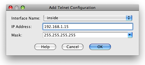
You can see in Figure 83 that we have enabled Telnet access on the inside interface for the host 192.168.1.15/32.
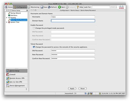
You now have to enter a Telnet password into the ASA. Navigate to Device Setup > Device Name/Password. Click the check box to change the Telnet password. By default, the old password is set to cisco. Enter a new secure password, and then apply it. Figure 84 shows the Device Name/Password screen.
SSH Configuration
SSH connection is the preferred method over Telnet. Because SSH provides strong authentication and encryption, SSH provides secure remote access to the command-line interface of the ASA.
Steps required to enable SSH are as follows:
Step 1: Configure hostname.
Step 2: Configure Domain Name.
Step 3: Generate RSA keys.
Step 4: Configure local authentication.
Step 5: Configure SSH on specific interface.
SSH configuration is similar to Telnet configuration. To configure SSH, navigate to Device Management > Management Access > Command Line (CLI) > Secure Shell (SSH).
As you did with Telnet, specify an interface, IP address, and subnet mask for the network that you want to grant SSH access to. Note that you can use SSH on the outside interface without requiring IPsec, because SSH itself supports strong authentication and encryption.
You require the Telnet password to be set so that you can use SSH to connect into an ASA. From the ASA client, you need to enter a command similar to the following:
userpc$ssh [email protected]
You are then prompted for the password; you enter the password you configured as the Telnet password. When you use SSH to connect into an ASA, the username you use is pix.
Software Image Configuration
The ASA relies on two main software images. The first is the ASA software image that runs the core operating system of the ASA. The second is the ASDM image. The ASA will work as a firewall without the ASDM image, but you will be unable to access ASDM and only able to configure the ASA with the CLI.
When you initially purchase an ASA, it comes with both an ASA software image and an ASDM software image already preinstalled on the ASA flash memory.
Command-Line Software Image Configuration
From the CLI, the command show flash displays which software images are located in the flash memory of the ASA:
ciscoasa#sh flash
--#-- --length-- -----date/time------ path
2 4096 Jun 26 2007 11:40:46 log
63 1868412 Mar 26 2007 08:33:42 securedesktop-asa-3.1.1.29-k9.pkg
64 398305 Mar 26 2007 08:33:54 sslclient-win-1.1.0.154.pkg
65 14524416 Jun 26 2007 11:39:02 asa802-k8.bin
67 4096 May 08 2007 12:13:20 sdesktop
70 50 May 08 2007 12:13:22 sdesktop/data.xml
68 6889764 Jun 26 2007 11:39:52 asdm-602.bin
6 4096 Jun 26 2007 11:41:02 crypto_archive
129073152 bytes total (105115648 bytes free)
From the preceding output, you can see there are eight files in the ASA flash. The ones we are interested in are asa802-k8.bin and asdm-602.bin.
The asa802-k8.bin file is the software image for the ASA (in this case, version 8.02).
The asdm-602.bin file is the ASDM software image (in this case, version 6.02).
The other files include the Secure Desktop, the SSL client, and the log file.
To add a file to flash from the CLI, you use the copy command. For example, to copy a file from TFTP to flash, you use the following:
ciscoasa#copy tftp flash
You are then prompted for the address of the remote TFTP server and the remote filename. In addition to TFTP, the following options are now available with the copy command:
ciscoasa#copy ?
/noconfirm Do not prompt for confirmation
/pcap Raw packet capture dump
capture: Copyout capture buffer
disk0: Copy from disk0: file system
flash: Copy from flash: file system
ftp: Copy from ftp: file system
http: Copy from http: file system
https: Copy from https: file system
running-config Copy from current system configuration
smb: Copy from smb: file system
startup-config Copy from startup configuration
system: Copy from system: file system
tftp: Copy from tftp: file system
As long as there is a single ASA software image in the flash, the ASA will always boot from this. If there are two or more ASA images in the flash, you have to use the boot system command from global configuration mode to tell the ASA which boot image to use.
If you have multiple ASDM images in flash, you have to use the ASDM image command from global configuration mode to tell the ASA which ASDM image to use.
ASDM Software Image Configuration
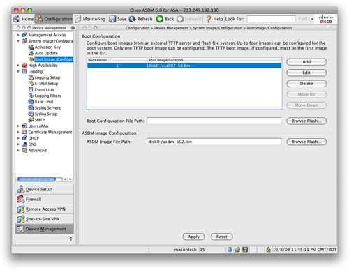
From the ASDM, navigate to the Device Management > System Image/Configuration > Boot Image/Configuration screen.
From this screen, you can add files to flash, remove files from flash, set the ASA boot image, and set the ASDM image (see Figure 85).
Licensing the ASA
The ASA is licensed with the use of activation keys. The activation key is tied to the serial number of the ASA, which is hard-coded into the operating code of the ASA.
To enable a feature, you need to purchase the required license. You then redeem this with Cisco after providing your serial number, at which time you will be provided an activation key. Because it is tied to the serial number, this activation key will work only on the ASA for which it was requested.
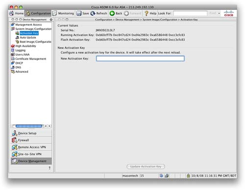
Navigate to Device Management > System Image/Configuration > Activation Key and enter the new activation key (see Figure 86).
The current license and features can be seen from the Home screen and the Device Dashboard in ASDM.
From the CLI, the show version command also provides information about the current licensing:
ciscoasa#sh ver
Cisco Adaptive Security Appliance Software Version 8.0(2)
Device Manager Version 6.0(2)
Compiled on Fri 15-Jun-07 19:29 by builders
System image file is "disk0:/asa802-k8.bin"
Config file at boot was "startup-config"
ciscoasa up 10 days 6 hours
Hardware: ASA5505, 256 MB RAM, CPU Geode 500 MHz
Internal ATA Compact Flash, 128MB
BIOS Flash LHF00L47 @ 0xffe00000, 1024KB
Encryption hardware device : Cisco ASA-5505 on-board accelerator (revision 0x0)
Boot microcode : CN1000-MC-BOOT-2.00
SSL/IKE microcode: CNLite-MC-SSLm-PLUS-2.01
IPSec microcode : CNlite-MC-IPSECm-MAIN-2.04
0: Int: Internal-Data0/0 : address is 001b.53a0.4e98, irq 11
1: Ext: Ethernet0/0 : address is 001b.53a0.4e90, irq 255
2: Ext: Ethernet0/1 : address is 001b.53a0.4e91, irq 255
3: Ext: Ethernet0/2 : address is 001b.53a0.4e92, irq 255
4: Ext: Ethernet0/3 : address is 001b.53a0.4e93, irq 255
5: Ext: Ethernet0/4 : address is 001b.53a0.4e94, irq 255
6: Ext: Ethernet0/5 : address is 001b.53a0.4e95, irq 255
7: Ext: Ethernet0/6 : address is 001b.53a0.4e96, irq 255
8: Ext: Ethernet0/7 : address is 001b.53a0.4e97, irq 255
9: Int: Internal-Data0/1 : address is 0000.0003.0002, irq 255
10: Int: Not used : irq 255
11: Int: Not used : irq 255
Licensed features for this platform:
Maximum Physical Interfaces : 8
VLANs : 3, DMZ Restricted
Inside Hosts : 10
Failover : Disabled
VPN-DES : Enabled
VPN-3DES-AES : Enabled
VPN Peers : 10
WebVPN Peers : 2
Dual ISPs : Disabled
VLAN Trunk Ports : 0
Advanced Endpoint Assessment : Disabled
This platform has a Base license.
Serial Number: JMX1113Z00E
Running Activation Key: 0xb10e4b44 0x28a8ad89 0xdc62d5c8 0xb6301430 0x870d098e
Configuration register is 0x1
Configuration last modified by enable_15 at 21:18:37.374 UTC Tue Oct 7 2008
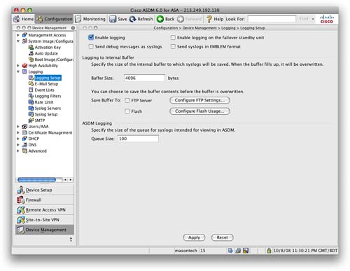
Configuring Logging on the ASA
Logging is disabled by default on the ASA. When you first connect to the ASDM, the first screen you will see is the Home screen and the Device Dashboard (see Figure 87).
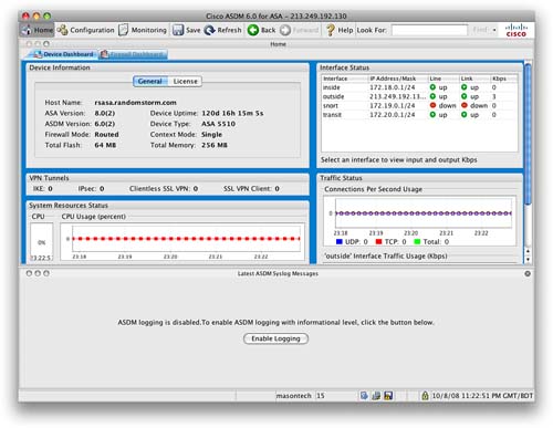
You can see from Figure 87 that ASDM logging is disabled. There is a button in the bottom half of the screen that will enable logging. Clicking this button enables logging on the ASA.
Figure 88 shows logging information on the Device Dashboard.
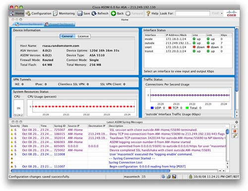
When logging is enabled, you can see the real-time log events in the Device Dashboard. You can also monitor logging events from the Monitoring toolbar.
From the Configuration toolbar, navigating to Device Management > Logging will provide you with more in-depth configuration options for configuring items such as external logging servers, log filters, and external email addresses. Figure 89 shows the Logging Setup screen.