
Chapter 2
Networking Foundations
 While it may not look like there are a lot of topics that are covered in the exam in this chapter, what is covered is foundational for much of what comes later. After all, unless you are sitting at the computer you are attacking, which would be very uncommon, you're going to be interacting with the network. In some cases, the different attacks, and certainly the defenses, will make use of networking technologies and communications protocols.
To understand how networks function, it may be helpful to have a conceptual understanding of how the protocols fit together. There is one conceptual model used to describe communication protocols and their functions. There is another way of describing these functions, sometimes called a model, but it's more of an as-built architectural design. In this chapter, I'll cover both the Open Systems Interconnection (OSI) model and the TCP/IP architecture.
You will be expected to understand network topologies. Topologies are generally conceptual and can be used as a way of logically organizing systems to see how they are connected. This will start us down the path of talking about the physical elements of networks, including how they are addressed. Ultimately, when we are networking systems, we want them to be able to communicate with one another. To do that, each system needs to have a way for others to address it. As you will see, each system will have multiple addresses. This refers back to the models mentioned earlier because the different addresses are ways of communicating with the different functions at different layers.
As we move up the network stacks from the physical components, we'll start talking about the protocols you are perhaps most familiar with: Internet Protocol (IP), Transmission Control Protocol (TCP), and User Datagram Protocol (UDP). These will be the foundational protocols you will need a solid understanding of for not only testing systems but also providing guidance as to how different vulnerabilities may be remediated by companies you are working for.
One common approach to providing information technology services in companies, especially if the services are to external users or customers, is to use service providers. Cloud computing can be used as an implementation of this type of outsourcing. Making use of these service providers and working with organizations that have placed systems and services with them introduces some specific challenges to someone performing security assessments or penetration tests. This means that understanding how these external service providers work can be essential.
Communications Models
We access systems through their addresses. The problem is that each system will have multiple addresses. These addresses are best separated into buckets related to the functionality provided by the protocol each address belongs to. The first communications model, from the standpoint of what we'll be talking about but also from the standpoint of history, meaning it essentially came first, is more conceptual than strictly practical. I will follow up with a practical model.
These communications models are broken into layers, and the layers are stacked on top of one another. Because it shows up as a stack of tiers, you will often hear them referred to as network stacks or protocol stacks. One important aspect to consider when it comes to these network stacks is that the layers are all separate and the functionality is distinct. When two systems are talking, each has these notional layers, and layer C on the first system can only talk to layer C, not layers B, A, or D, on the second system. This is because the protocols at layer C on both systems match. The same is true for the other protocols. As an example, you can see a set of network headers in Figure 2.1. The layer/function that generated this set of headers on the sending side can be read only by the same layer/function on the receiving side.
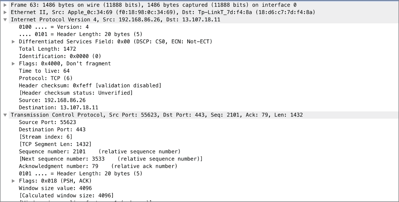
FIGURE 2.1 Network headers
As we go through the two communications models, I'll talk about not only the functions that exist at each layer, but also the protocols that exist at each layer. When we're done, you'll have two different, but not dissimilar, ways of understanding how protocols communicate across systems and how messages between systems/applications are put together.
Dissecting the functions of network communications into layers means the functions are modularized. This means that it can be easy to extract one protocol from the chain and insert another one. The same applications work over Ethernet, for example, as the ones that travel over SONET or Frame Relay. All these protocols exist at the same layer. This works because the functionality of each layer is abstracted, meaning layers can communicate with each other without needing to know the details because the functionality is known. The individual protocols don't matter, necessarily. There are many different protocols for each of the layers, no matter which model we are talking about.
Open Systems Interconnection
Prior to the late 1970s, communications systems used proprietary protocols, making it harder to conceptualize what was happening. Each protocol defined different communications in different ways. In the late 1970s, the International Organization for Standardization (ISO) began a process to define a set of standards for communication. The idea behind this was to allow for better interoperability between vendors. If all the functions are broken out conceptually, the interface points are clearer and, as such, easier to interact with.
In 1978, an initial model was announced. After refinements, it was published as the OSI model. While there were concerns about the complexity of this model and the chance that it was unlikely to be implemented, it remains a solid model to help refer to boundaries between functions within a network stack. The OSI model includes seven layers. When indicating a particular functionality, network professionals may make reference to the function by the layer number. We'll see how this works shortly.

FIGURE 2.2 The seven layers of the OSI model
Figure 2.2 shows the seven layers of the OSI model. In talking about the model, we typically start at the ground floor and work our way up to the penthouse. At the bottom of the model is where you connect to the network. At the top is where you interact with the user.
Since we build messages from the Application layer down, we're going to start discussing each of the layers and their roles there and move downward. For what it's worth, though, the various mnemonics that are often used to help people remember the different layers start at the bottom. For example, one of my students once suggested “Please Do Not Touch Steve's Pet Alligator” to help remember the order. That's bottom to top, though. Regardless, if you remember either order and then can remember what each of the layers does, you'll be in good shape.
- Application (Layer 7) The Application layer is the one closest to the end user. This does not mean that it is the application itself, however. We are talking about protocols. Application layer protocols manage the communication needs of the application. They may identify resources and manage interacting with those resources. As an example, the Hypertext Transfer Protocol (HTTP) is an Application layer protocol. It takes care of negotiating for resources (pages, etc.) between the client and the server.
- Presentation (Layer 6) The Presentation layer is responsible for preparing data for the Application layer. It makes sure that the data that is handed up to the application is in the right format so it can be consumed. When systems are communicating, there may be disconnects in formatting between the two endpoints, and the Presentation layer makes sure that data is formatted correctly. As such, character encoding formats like the American Standard Code for Information Interchange (ASCII), Unicode, and the Extended Binary Coded Decimal Interchange Code (EBCDIC) all belong at the Presentation layer. Additionally, the Joint Photographic Experts Group (JPEG) format is considered to be at the Presentation layer.
- Session (Layer 5) The Session layer manages the communication between the endpoints when it comes to maintaining the communication of the applications (the client or server). Remote procedure calls (RPCs) are an example of a function at the Session layer. There are components of file sharing that also live at the Session layer, since negotiation of communication between the endpoints needs to take place. The Application layer takes care of managing the resources while the Session layer takes care of making sure that files, as an example, are successfully transmitted and complete.
- Transport (Layer 4) The Transport layer takes care of segmenting messages for transmission. The Transport layer also takes care of multiplexing of the communication. Both the TCP and the UDP are transport protocols. These protocols use ports for addressing, so receiving systems know which application to pass the traffic to.
- Network (Layer 3) The Network layer gets messages from one endpoint to another. It does this by taking care of addressing and routing. The IP is one protocol that exists at this layer.
- Data Link (Layer 2) One other address to contend with is the media access control (MAC) address. This is a layer 2 address, identifying the network interface on the network so communications can get from one system to another on the local network. The Address Resolution Protocol (ARP), virtual local area networks (VLANs), Ethernet, and Frame Relay are Data Link layer protocols. They take care of formatting the data to be sent out on the transmission medium.
- Physical (Layer 1) This layer probably speaks for itself. This is all the protocols that manage the physical communications. 10BaseT, 10Base2, 100BaseTX, and 1000BaseT are all examples of Physical layer protocols. They dictate how the pulses on the wire are handled.
One of the problems with the OSI model is that there are not always good fits when it comes to mapping protocols to the seven layers. The problem often comes in the areas between the Session and Application layers. As an example, at which layer does the Secure Shell (SSH) protocol live? Is it the Session layer because it ultimately manages sessions, or is it the Presentation layer because it includes encryption mechanisms and negotiates them? Other protocols seem to exist between layers. ARP, for instance, is said to operate at the Data Link layer, but it needs to know about the Network layer because it provides the bridge between the addressing in those two layers.
However, there are places where having the model makes conceptualizing things much easier. For example, you probably have a device in your home that's very confusing. You may call it a router, or you may know people who call it a router. The problem is that routing is a layer 3 function, as discussed earlier, and there are other functions in the device that are strictly layer 2, meaning you have switch ports that transmit messages on your local network where there is no routing involved. Additionally, it's entirely possible your device isn't even doing any routing, but instead it may be bridging to your provider's network. It all depends on how your device is working and what your provider is expecting from your device. This is where understanding the different layers is helpful. You can better identify where you may have problems because you can isolate functionality.
TCP/IP Architecture
In the late 1960s, the ARPAnet was first developed and implemented. Over the next few years, it grew far beyond the initial two and then three nodes that were connected in 1968–69. As more systems were connected to the network, the people responsible for managing the network and developing the protocols used to exchange information learned a lot. The initial protocol was the 1822 protocol that defined communications to the Interface Message Processor (IMP), which was a large computer with specialized interfaces acting as a message gateway (think of it as a very primitive router). The 1822 protocol was later replaced by the Network Control Program (NCP).
By 1983, after many years of development, the NCP was replaced entirely by a suite of protocols now commonly called Transmission Control Protocol (TCP)/Internet Protocol (IP). The way the suite of protocols used within TCP/IP stack is described is slightly different from the way the OSI model is described. After TCP/IP was implemented, the conceptual design of the protocols was described. For this reason, the suite is sometimes referred to as a model, but it may also be referred to as an architecture, since it's a description of an as-built design rather than something conceptual. OSI is entirely conceptual since it didn't describe anything in particular.
The TCP/IP architecture is a much simpler design than the OSI model, which is an immediate difference and a reflection of the as-built nature of the design as compared with the conceptual design of the OSI. Since the OSI model had to be abstract and flexible to accommodate a wide variety of protocols and designs, it was broken out into the seven functional categories described earlier. TCP/IP, on the other hand, as an as-built definition, is only four layers.
This is not to say that there is no correlation between the OSI model and the TCP/IP architecture. As you can see in Figure 2.3, there is much that is similar between the two.

FIGURE 2.3 The TCP/IP architecture layers
You'll notice the similarities. For a start, there is an Application layer in both. There is also a Transport layer. The Internet and Network layers are named very similarly. Essentially what happens is that the Session, Presentation, and Application layers from the OSI model are collapsed into the Application layer in the TCP/IP model. Additionally, the Physical and Data Link layers from the OSI model are collapsed into the Link layer in the TCP/IP model. The same functions from the collapsed layers exist in the TCP/IP model. Conceptually, though, it's easier to understand. Anything related to the application communication, including any session management and data formatting, is in the Application layer. Similarly, in the TCP/IP model, the Physical layer and the Data Link layer are put together.
Regardless of which model you prefer to think about networking in, you'll find that protocols don't generally sprawl across multiple layers. They are designed to fill the requirements of a specific function, which will land pretty squarely into one of the layers of each model.
In the rest of the chapter, and fairly commonly in the real world in my experience, when you see a reference to layers, the reference is to the OSI model and not the TCP/IP architecture.
Topologies
The way networks are designed also uses conceptual models, as a way of taking a rat maze of physical networks and mapping them to a logical representation. This is not only about getting a logical map of the network but also helps to identify how everything is connected since it will help to isolate potential issues. Different topologies introduce different potential problems. You'll also typically find that some topologies are only found in certain situations. Some will be found in service provider networks, while others are more commonly found in local area networks.
Bus Network
A bus network, as shown in Figure 2.4, consists of a single network cable to which every device on the network connects. A bus is a communication channel. You may find a bus inside your computer to communicate between channels. In our case, it's a communication channel (a single network cable) that allows the communication between multiple computers. The way some bus networks work is by using a coaxial cable with T-connectors. The T-connector provides a way to extract the signal from the bus in order to provide connectivity to the systems on the network. This type of bus network requires something on the end of the cable to keep the signal on the wire. These electrical devices are called terminators. You can see the blocks on the end of the bus. They keep the signal from reflecting back onto the wire, causing cancellation of the signal.

FIGURE 2.4 Bus network
What you will notice with the bus network is that there is no mediating device. All of the computers are connected directly to one another by means of that single network cable.
Star Network
When you see a diagram of a star network, it will often look similar to the bus network. The difference between the bus and the star network, however, is that there is a mediating device between all the devices. This may be a hub, if you have a very old network, which is a dumb electrical repeater, or you may have a switch. You can see a traditional diagram in Figure 2.5. In the case of this diagram, the central line you see, which looks like a bus, is really a switch or a hub. These devices will then send the signals that come in back out to the other devices. In the case of a hub, every device on the network will get it. If your network uses a switch, the signal will be sent to the correct port.

FIGURE 2.5 Star network
And this is where the different layers are helpful. A switch, which is the most common device in a star network topology, acts at layer 2 of the OSI model. It uses the MAC address to make decisions about where traffic goes. In the case of a star network with a hub, there are the same issues as there would be with a bus network—lots of collisions where messages sent out on the wire run over other messages sent by someone else. A switch alleviates those issues because only traffic addressed to a system gets sent to that system.
Ring Network
A ring network is similar to a bus network in the sense that all of the nodes on the network appear to be connected on a contiguous network segment. Traffic passes around the ring from system to system. You can see a logical representation in Figure 2.6. The reason it's a logical representation is because physically, this is not how these networks are wired. One type of ring network is a token ring. In a token ring network, systems are wired as though they are in a star, using multistation access units (MAUs). While they are wired that way, they don't behave like a star. This is where you should remember that these are conceptual models. The behavior, regardless of the wiring, is how the topologies are named.

FIGURE 2.6 Ring network
Just as with a bus network, there is a problem with collisions. A token ring network avoids this problem by using a talking stick. Just as when you are sitting around a campfire in an aboriginal tribe, where only the person with the stick gets to talk, a token ring network uses a digital representation of the talking stick called a token. Only the system that has the token gets to talk. If there is no system that needs to send a message, the token gets passed from system to system. When a system needs to talk, it has to wait for the token to get passed around to it. This will theoretically avoid the problem with collisions except that sometimes the token gets lost, which means a new token has to get generated. After the new token gets generated, it's possible for the old token to suddenly get “found” again, meaning there are two tokens on the network.
In spite of a ring network behaving like a bus network, there isn't a need for terminators as there is in a bus network. The hardware necessary to have the network function as though it were in a ring configuration takes care of the problem of echoes back to the wire.
Mesh Network
In another topology, systems are wired directly to one another. Figure 2.7 shows an example. This looks a little as though they are wired in a ring, but it's more like peer to peer. To get from one system to another, if they are not wired together directly, a system has to pass through another system. Mesh networks will typically avoid another potential problem with a bus network. If a system in the middle of the bus network fails, there is a potential for the entire network to fail along with it. The system essentially acts like a terminator by not allowing the electrical signal to pass through it. If a system in a mesh network fails, there is probably another pathway to get between one system and another.

FIGURE 2.7 Mesh network
While you can connect systems together in multiple ways in a mesh network, in spite of the orderliness that the circular design of the network shows, a couple of failures can potentially isolate nodes in a mesh network. The way around that is to add connections. The more pathways to get from one system to another, the less chance failure will be catastrophic, meaning communication doesn't happen. You can keep adding connections until every system has connections to every other system on the network. You can see an example of this type of design in Figure 2.8. What you see in the diagram is what's called a full mesh network. Every system in the network has a connection to every other system.

FIGURE 2.8 Full mesh network
The problem with adding more connections is the resulting complexity. You can see a little of that. Diagramming it makes it hard to see where all the connections are. Every time you add a node to the network, you don't just add a single connection. You add the same number of connections as you have existing nodes, so your connections increase nearly exponentially. In fact, to determine the number of connections you have, you can use the formula n(n – 1)/2. Every system has a connection to every other system except itself, which is why we multiply the number of systems by one less than the number of systems. (For example, if you had 5 systems, the formula would look like 5(5 – 1)/2. That would be 5 * 4, which is 20, divided by 2, giving you 10 connections.) We divide by 2 because we aren't going in both directions from one system to another. We need only a single connection.
Hybrid
Each of the previous topologies is good, given the right circumstances. However, there are circumstances where blending multiple network topologies is the right way to go about connecting your network. One common hybrid approach is the star-bus. If you have switches capable of 64 network connections but you have 200 users that you need to connect to your local network, you would need to add a bus into your network topology. The bus would connect all of your switches together and become a backbone for your network. Then from each switch, you have the traditional star where all the connections come back to the switch they are connected to.
Similarly, it may be helpful to connect your switching infrastructure in either a mesh or a ring. This may be for redundancy purposes, to ensure multiple pathways to get to all of your network. If everything was in a bus and the bus failed, some network segments may be isolated. As a result, setting up your network with multiple pathways can make a lot of sense. A mesh network or a ring network may help with that.
Physical Networking
At some point, you need to connect to the network. There are multiple components to that interaction. You need a network interface on your end. You need a medium that is going to carry the communication. You need to have something on the other end of the communication. Because we aren't likely going to be working at service providers or telecommunications providers as we are doing security testing, at least not on the provider side of the network, we aren't going to worry about protocols like Frame Relay, Asynchronous Transfer Mode, or Fiber Distributed Data Interface. The protocol you will almost exclusively run across when we are talking about physical networking is Ethernet.
Each layer of the network stack has a different term to refer to the chunk of data encapsulated by that layer. These chunks are called protocol data units (PDUs). The PDU at layer 2, which is a part of what we are talking about here, is a frame. When you are looking at a chunk of data with the physical address in it, you are looking at a frame. We'll talk about the names of the other PDUs when we get to those layers.
Addressing
Ethernet interfaces all have addresses. These addresses are exclusive to each network interface, and they are called MAC addresses. Because the MAC address is hard-coded into the hardware of the interface, it is sometimes referred to as the hardware address. Since it's also the address that is used by a physical piece of hardware, it is sometimes referred to as a physical address.
The common format of a MAC address is 6 octets (8-bit bytes) generally separated by colons. An example of a MAC address would be BA:00:4C:78:57:00. The address is broken into two parts. The first is the organizationally unique identifier (OUI). This is also called the vendor ID because it identifies the name of the company that manufactured the interface. The second half of the MAC address is the unique address within the vendor ID of that interface. So, half is for the vendor, and half is for the card itself.
The MAC address is used exclusively on your local network. Any system that wants to send you anything will address it to your MAC address. You can also send messages to every device on the network by using the broadcast address. The broadcast MAC address is ff:ff:ff:ff:ff:ff. Your network interface knows what address it has, because it's in the hardware. What this means, though, is that traffic that is in some way addressed to the interface, either directly to its address or to the broadcast address, for example, will get forwarded up to the operating system from the network interface. Everything else will get ignored, unless the interface is told specifically not to ignore it. This would be an unusual case, though it is necessary for packet captures.
Switching
MAC addresses are the cornerstone for switching. Switching is what happens when decisions about forwarding messages are made based on the physical address. A switch is really a multiport bridge. Traffic is forwarded from one interface to another based on what the destination MAC address is. This does, though, mean that the switch needs to know what MAC address lives at which port. It does this by waiting until a message comes in on each port and notices the source address.
Because having to perform a lookup of which port to forward a message to takes time, which will slow down message transmission, it's essential that the lookup be as fast as possible. This is generally accomplished through the use of something called content-addressable memory (CAM). This means that to look up a value, you search for it based on another value. Instead of an array of data indexed with numeric values, meaning we look up a value by using something like array[5] to get the value at index 5 in the array, we use a MAC address as the index value. This means that you need to search through all the data or keep it sorted in order to find anything. This is time-consuming. It's easier to look up a port value by just indexing to the MAC address.
What a switch does, which is the value of switching, is make determinations about what traffic goes to which port based on the destination MAC address. This reduces the amount of traffic going out the switch port and down the wire. This improves performance because you can fill the network connection with traffic specific to the system connected to the switch port rather than flooding it with all the other traffic on the network. This does cause some other problems, though, when it comes to security testing. In a switched environment, you only see traffic meant for that system connected to the switch port. When performing security testing, acting like an attacker, it's more convenient to be able to see more traffic than that.
There are some ways around that challenge. One of them, if you have some control over the switch, is to tell the switch to mirror traffic on one port to another port. Then, you need to have the system you are running attacks from attached to the mirror port. Another way is to fool the switch into sending traffic to you, which involves methods of attack that we'll cover in later chapters.
IP
Moving into the Network layer, we run across IP. Certainly there are other protocols that exist at the Network layer, such as the Internet Packet Exchange (IPX), but as the Internet runs on IP and its associated protocols, we'll focus there. So far, we haven't talked much about headers. As each layer is passed through, a set of data is added to the message that is specific to the protocol processing the message. This set of data is called headers. Each protocol has its own set of headers that get attached. The message is then encapsulated by the headers, creating an entirely new PDU. For IP, the PDU is called a packet. You may hear every set of data on the network referred to as a packet, but from a technical standpoint, a message from the IP header down is a packet.
Addressing is something to consider, as well. This is an aspect that people who work with networking are often fairly familiar with, but it's useful to understand what an address comprises. Associated with the address is the subnet mask. This can be challenging to understand, but there are some mathematical tricks that can help, once you know them. There are also a couple of different ways to render the subnet mask, and you'll often run across both of them.
There are currently two versions of IP in use. The one that is most common is version 4, commonly designated as IPv4. We've been in the process of switching over to version 6 for the last couple of decades. It hasn't happened yet, but every modern device and operating system supports IPv6, so you will see the IPv6 address on most systems you will interact with. IPv6 has some differences over IPv4, not the least of which is the size of the address space.
IP is considered a best-effort protocol. It does its best to get packets from the source to the destination. It does nothing to absolutely ensure that they get there. It does facilitate the transmission, however, by providing addressing.
Headers
The Internet Engineering Task Force (IETF) is responsible for maintaining all of the documentation related to protocols. When someone, or more commonly a group of people, wants to propose a new protocol or an extension to an existing protocol, they write something called a request for comments (RFC) document. The IETF not only maintains the RFCs, but it also manages the process of getting them approved. The first RFC was written in 1969 and was related to the host software for the IMP that was used to interface a computer system to the ARPAnet. At the time, of course, the IETF didn't exist, but using RFCs was still the process for creating specifications and standards.
The RFC for IP, which was published in 1981, is 791. It defines how IP is supposed to work and also defines the header fields used by IP. Figure 2.9 shows a set of IP headers from a message captured off the network. This is the same set of headers that would be presented in the form of a table in the RFC referenced. The difference between the table form and just looking at the headers in this way is that with the table, you can clearly see the size of each header field.

FIGURE 2.9 IP headers
The following are the header fields with their descriptions and sizes:
- Version This field indicates which version of IP is in this packet. This is a 4-bit field.
- Header Length This field indicates how many words are in the IP header. Because the header is based on 32-bit words, which is 4 bytes, you can get the number of bytes by multiplying this value by 4. In the case of this example, you'll find that the headers are 20 bytes (five words), which is common for an IP header.
- Type of Service The RFC calls this the type of service (ToS) field, though you'll also see it referred to as the differentiated services field. This field helps network elements make quality of service (QoS) decisions by prioritizing some messages and deprioritizing others. This is an 8-bit (1-byte) field.
- Total Length This is the total length of the message, including the IP header and any subsequent data. This does not include any header that gets added on after the fact, like the layer 2 header. This field is 2 bytes long, which allows for a total message length of 65,535 octets (bytes).
- Identification Sometimes there is too much data being sent to fit into the maximum length allowed based on the size of the length field. This means the messages sometimes need to be fragmented. All messages sent get this field set, though it only means anything if there are fragments. All fragments will have the same identification value.
- Flags There are 3 bits allocated to a flags field. One is reserved, and the second indicates whether the message can be fragmented. This is sometimes called the DF bit. If it's set, it means don't fragment the message. The last bit is used to indicate whether there are additional fragments. If it's set, there are more fragments. If it is unset (meaning 0), it's the last fragment. A message that is self-contained, meaning it didn't require any fragmenting, would have this bit clear.
- Fragment Offset The fragment offset field, 13 bits long, indicates where the data in the packet aligns. This lets the receiving system know how to stitch all the fragments together. The value in this field is in double words, or 8 octets (bytes).
- Time to Live The time to live (TTL) field indicates how long a message can live on the network before it is considered to be expired. It is meant to be measured in seconds, though every network device that touches the message must decrement this field. Since the packet may pass through multiple network devices in a second, the initial definition of this field isn't relevant anymore, and the TTL really indicates the number of network devices (routing devices, essentially) the message can pass through. Once the field hits 0, the message is discarded, and an error message is returned to the sender. This field is 8 bits long.
- Protocol This is a numeric value indicating what the next protocol is. It is an 8-bit field and tells the receiving system what headers to look for in the transport header. In the case of the packet in Figure 2.9, the value is 17, which means it's a UDP message.
- Checksum This is a 16-bit value that is used to determine whether the header is intact. It is defined as a 1's complement sum of the 16-bit words in the header.
- Source Address This is the IP address that sent the message. It is 4 octets in length.
- Destination Address This is the IP address that the message is going to. It is also 4 octets in length.
Addressing
IP version 4 addresses are 4 octets long. They are commonly shown as being separated by a period (.). Because of this, they are sometimes referred to as dotted quads. Since each value is 8 bits, there are potential values of 0 to 255. Not all values, especially in the first two octets, are used, however. There are some addresses that are held in reserve, for various reasons. For a start, the address range 127.0.0.0–127.255.255.255 is reserved for loopback addresses. These are addresses that refer to the host they are assigned to. The loopback interface ensures there is always a network interface on the system and allows for testing over a network without sending any traffic outside the system. Commonly, the loopback address on systems is 127.0.0.1, though any address in that range could be used.
RFC 1918 also carves out ranges of IP addresses that are used for private networks. By convention, these addresses are not routable over the Internet. Most networks will do something to block source addresses from these ranges coming into their space, since they should never be originating from the outside of a network. The ranges for these private addresses, meant to be used by any network that doesn't have public IP addresses, are 10.0.0.0–10.255.255.255, 172.16.0.0–172.31.255.255, and 192.168.0.0–192.168.255.255.
Additionally, other address ranges are held in reserve. The range 224.0.0.0 through 239.255.255.255 is used for multicast messages. Anything above 240.0.0.0 is also reserved and is not currently in use.
One of the reasons for moving to IPv6 is the limitation on addresses with version 4. There are approximately 4 billion addresses available with IPv4. This includes the entire set of addresses, though. Out of that, we lop off 16 million right away just because of the 10.0.0.0 private address block. Then, we take away more than 268 million because of the addresses higher than 240.0.0.0. You can see how quickly address space in IPv4 disappears. You may also have noticed that the number of devices that are connecting to the Internet is increasing at a nearly exponential rate. The stopgap for this is to use private address ranges on the inside of networks, especially home networks.
Instead of just 4 octets that are used in IPv4, IPv6 uses 16 bytes. Because it would be awkward to write an IPv6 in dotted octet form as we do with IPv4, addresses in IPv6 are written in a different form. Because an octet can be represented with two hexadecimal digits, you will see IPv6 addresses represented in that way. It saves space and typing. Since there are 16 octets in an IPv6 address, the longest address you will run across will be 32 characters. However, the complete address is generally separated into byte pairs with a colon (:) between. As an example, one of my systems has an IPv6 address of fe80::62e3:5ec3:3e06:daa2.
In addition to the address being broken up into byte pairs, like fe80, you'll notice there is a part of the address that has a colon pair with nothing in between. This is not a mistake. This is a shorthand to indicate that what is in the middle is all 0s. The complete address would be fe80:0000:0000:0000:62e3:5ec3:3e06:daa2. It's easier to drop the extra 0s out.
IPv6 has three different address types. The first is unicast, which refers to a single system. Anycast addresses are groups of systems that share a single address. A message sent to the anycast address will be delivered to just one of the hosts in the anycast group. This will commonly be the closest address, based on routing rules. Any anycast address will have the same format as a unicast address. Multicast addresses will look like the other addresses, but they are formatted based on the fact that they are multicast addresses and on the application that is using the address. You may see a multicast address like 224.0.0.1, for example.
Subnets
Subnetting can be a challenge to understand, but it's an important concept. One of the reasons it's important is that you may need to know what addresses belong to your target based on a subnet. If you don't get the subnet boundaries correct, there is a chance that you will start testing against systems that don't belong to your target. This can get you into a lot of trouble. Because of that, we'll spend a little time here talking about what subnets are and how to determine the boundaries of subnets. This will involve some simple math, but ideally it will be easy once it's explained to you.
IP addresses are aggregated into networks using contiguous addresses. This is relevant no matter whether we're talking about IPv4 or IPv6. This makes routing to those addresses easier since routing tables don't have to keep track of every single IP address. Instead, the aggregate blocks are tracked. In part because of this, a part of the IP address belongs to the host and part belongs to the network. This segmentation of the address also helps systems to know what addresses are local, meaning the communications stay on the local network. The way systems are told what are local networks and what are not local networks is that a subnet mask is paired with the IP address.
The subnet mask is also 32 bits in length and represented as a dotted quad. To determine what portion of an IP address belongs to the network, you look at the bits that are set to 1 in the subnet mask. To better understand this concept, let's take a look at a binary representation of a subnet mask.
- 11111111.11111111.11111111.10000000
Any bit position that has a 1 in it is part of the network segment. You'll notice that the 1s are filled in from the left and there are no gaps. As a result, subnet masks can have only certain values: 0, 128, 192, 224, 240, 248, 252, 254, and 255. This is because every position is a power of two and we add on from the most significant bit on the left side. The binary 10000000 equals 128 in decimal. 11000000 is 192. Every time we set a bit to 1, we add on the next lower power of 2. Looking at the subnet mask above and applying binary to decimal translation, we can see that the subnet mask is 255.255.255.128. This means that only the last 7 bits of the last octet are used for host values. The bit representation in the last octet would be 10000000. This is where we need to start applying the IP address to the subnet mask to get the address range.
With a subnet mask of 255.255.255.128, I have the possibility of two address blocks, regardless of what the IP address is. I can only vary the last octet, and I am constrained because I can't change the value in the most significant bit position. This leaves me with the ranges of 0–127 and 128–255. Once I know what my IP address is, I know which block I am in. Let's say my IP address is 172.20.30.42, and my netmask is 255.255.255.128. I know my address block has to be 172.20.30.0–127 because that's the range that .42 lands in.
Another way of designating network blocks is using Classless Interdomain Routing (CIDR) notation. This means that rather than indicating a subnet mask, you only get the number of prefix bits. The prefix tells you which bits are being used for the network. The subnet mask used above translates to /25, and I would indicate the subnet with the IP address by indicating 172.20.30.42/25. Using this notation actually makes life a little easier if you think about it in powers of two.
Let's say you want to know how many addresses belong to a particular network block and you have the CIDR notation. One way to make that determination is to start with a known quantity. Often, you will see CIDR notations hovering around the /24 area, which is a 255.255.255.0 subnet mask and is common. If you want to know how many hosts, you just divide by 2 or multiply by 2 for every bit change in the prefix. A network that is a /24 has 256 possible values in the host portion (the last octet). If you go to a /25, that means you get 128 possible values (divide by 2 because you added a prefix bit, meaning you lost a host bit). If you go the other direction to a /23, you double because you lost a prefix bit, meaning it got added to the host portion. Instead of 256, you now have 512 possible values in the host portion.
You can also see pretty quickly how to get even smaller prefix values just by looking at the number of bits in each octet. If the first octet is used for the network designation and all others are used for the host values, you would have all the bit positions in that first byte filled up, which means you are using 8 bits, leaving you with a CIDR designation of /8. Similarly, if you use the first two octets, you are using 16 bits, so you have a /16.
One note about subnets, though, is that there are two values that can't be used for systems. The lowest possible address in any network segment is used for the network. The highest possible address in any network segment is used for the broadcast address. In a common /24 network, the .0 becomes the network address, and the .255 is used for the broadcast. Neither of these can be allocated for hosts.
IPv6 makes the whole process even easier. There are no subnet masks used any longer. Instead, CIDR designation is used exclusively to indicate which part is network and which is host. The same rules apply. The network portion always starts from the left, and we fill in bits of the mask from the left. A /50 network means that the first 50 bits of the address are the network designation. This leaves the remaining 78 bits (keep in mind that IPv6 addresses are 128 bits long) for the host. That would be an incredibly large network, of course.
TCP
Moving to the Transport layer, we first run across the TCP. Where IP is a best-effort protocol, meaning that a best effort is made to get messages from one system to another, TCP is said to have guaranteed delivery. This is less impressive, perhaps, than it sounds. Obviously, TCP by itself can't ensure delivery in the case of catastrophic failure in the network. Instead, what it means is there are mechanisms in the protocol that keep track of all of the messages that are sent, and if something doesn't get to the other end and acknowledged there, messages will be re-sent.
The layers we have looked at so far have forms of addressing. The Transport layer is no different. Where previous addresses are related to the systems to ensure messages get from one system to another, at the Transport layer, we start to become concerned about getting messages to the application. Transport layer protocols provide ports as a way of addressing applications. They also provide multiplexing. Without ports, we wouldn't be able to have multiple applications listening on the same system. With ports, we have a large capacity for conversations with other systems.
Just as we did with IP, we're going to take a look at the headers that are defined for TCP. TCP is defined in RFC 793, and it was also written in 1981, which means TCP has been around for a long time. The headers remain unchanged in all that time, and since the headers enable the functionality of the protocol, the functionality hasn't changed either. Figure 2.10 shows the TCP headers from a packet capture.

FIGURE 2.10 TCP headers
You will see the following fields in the capture:
- Source Port The source port is the port that the traffic originated from on the sending side. This is important because conversations are not one-way. For the recipient to be able to respond, it needs a port to send back to. When messages are responded to, the source and destination ports are reversed. The source port is 16 bits in length.
- Destination Port The destination port is the one that is associated with an application. Every conversation has a client side and a server side. The server side binds an application to a listening port. The client sends to this port as the destination port. If the server is sending from the server to the client, the destination port is the ephemeral port assigned to the application that is communicating with the server. The destination port, like the source port, is 16 bits in length.
- Sequence Number The sequence number is part of what contributes to the guaranteed delivery. This is a 32-bit number that is set to a random value when the conversation is initiated. It is incremented with the number of bytes that are sent. Using the sequence number, the sender tells the recipient where in the conversation this message falls. You'll see in the example that the sequence number shows as 0. The reason for this is that the packet capture software shows a 0 and then presents relative sequence numbers, which are easier to follow.
- Acknowledgment Number The acknowledgment number is the opposite side of the conversation from the sequence number. Where the sequence number is set from the sender, the acknowledgment number is set from the recipient. The acknowledgment number is set to the next byte number the recipient expects to receive. What this means in practice is that the byte count is incremented by 1 and then sent. This tells the sender where in the communication stream the recipient is, which lets the sender know whether anything has been lost in transmission.
- Data Offset The data offset is a 4-bit value indicating the number of 32-bit words in the TCP header. It lets the system know where to look for the data. This is necessary because the TCP header can be variable length. This field isn't shown in the figure, but it is a defined TCP header.
- Reserved There are 6 bits in the TCP header that are reserved for future use.
- Control Bits There are 6 flag bits that are used to indicate disposition of the message. The SYN flag is the synchronize flag, indicating that the sequence number is set and should be recorded. The ACK flag is the same for the acknowledgment number. The URG flag indicates that the urgent pointer has data that is significant. The PSH flag is an indication that the data should be pushed up rather than being buffered. The RST flag resets the connection, which may happen if a message is received that appears to be in error. The FIN flag indicates that the conversation is over and there is no more data to send.
- Window The value in the window field tells the recipient how many bytes the sender is willing to accept. This allows for speeding up and slowing down the communication. A smaller window size means more acknowledgments are necessary, which may be an indication that the communication channel isn't reliable. A larger window size means the channel is reliable so there isn't as much need to keep checking in. The window field is 16 bits.
- Checksum This is a 16-bit field used to ensure that the communication hasn't been corrupted. This is a 1's complement value calculated over the headers and the text.
- Urgent Pointer The 16-bit urgent pointer indicates the next byte value after the urgent data. This aligns with the sequence number values. Essentially, the urgent pointer says the data from the current sequence number up until the value in the urgent pointer is urgent data.
- Options These are variable length header fields. The header must align on 32-bit words. If the options leave the header length short of that alignment, padding bits are necessary to fill the remainder of the header.
TCP uses multiple mechanisms to ensure a reliable service. The first is that TCP is connection-oriented. Connections are established using what is called a three-way handshake. Figure 2.11 shows a diagram of the handshake process. The handshake ensures that both sides of the conversation are live and active because they are expected to respond. The first message in the three-way handshake is the SYN message. The SYN flag is set, as well as the initial sequence number, which is a random value. The response to the SYN message is an acknowledgment message. This sets the ACK flag and increments the initial sequence number by one, indicating the first message was received. In the same segment, the SYN flag and sequence number are also set. Keep in mind that the conversation is two-way, so both sides have to keep track of where they are in the conversation. Each side keeps track of a sequence number for their side and an acknowledgment number for the other side. The final message in the handshake is one that just has the ACK flag set, and the acknowledgment field increments the sequence number set in the SYN/ACK message.

FIGURE 2.11 Three-way handshake
Since both sides are expected to respond to messages with information provided by the other, we can be assured that the message was received by the intended party and both sides are who they claim to be. If either side were attempting to spoof a conversation, they wouldn't receive the messages and, as a result, wouldn't respond correctly.
The next mechanism that helps ensure reliability is the sequence number. Since the sequence number maintains the number of bytes that have been sent, the acknowledgment number tells the sender whether any data has gone missing in transmission. If it has, the sender knows it needs to be retransmitted. Each side of the conversation knows where it is and where its partner is. TCP retransmits as needed, up to a defined maximum.
Additionally, the sequence and acknowledgment numbers ensure the correct order of messages at the recipient. If messages arrive out of order, the sequence numbers indicate whether messages should be held for a message that got lost. This is also a part of guaranteed delivery—making sure that the messages not only arrive as expected but also are in the correct order when they get there. All of this, though, incurs overhead. Not every application needs the guaranteed delivery model that TCP provides.
UDP
The UDP offers another mode of transport that doesn't have the same overhead that TCP has. It's a much lighter-weight protocol that offers no guarantee of delivery. Messages sent using UDP are just put out on the wire with the hope that they will get to the destination because the network protocol, IP, will just take care of everything. With the lighter weight comes very little overhead from things like establishing connections and making sure that messages get where they are going. It also doesn't much matter which order messages are received in from the standpoint of the protocol. If the application is interested in those sorts of details, it can take care of the management.
The RFC for UDP is RFC 768. The entire RFC is a little over two pages long, which should make clear how simple the protocol is. You can see an example of a UDP header in Figure 2.12. There are four header fields. All of them are 16 bits in length. Unsurprisingly, half of them are the source and destination ports. What's interesting about that is the source port is considered an optional field. The reason for this is that since there is no connection, there may never be a response from the server. It's entirely up to the application in use, which is different from TCP. A source port is required with TCP because there will always be a response, even if it's just used to complete the three-way handshake.

FIGURE 2.12 UDP headers
Interestingly, perhaps, RFC 768 does not define a response to a closed UDP port. In fact, closed ports are not mentioned. The only place where responses to closed ports are mentioned that is relevant is in the RFC for the Internet Control Message Protocol (ICMP). Even then, there is just a code for port unreachable. There is no indication about protocol where it applies. For this reason, working with UDP ports is entirely unreliable. If you don't get a response, it could be a result of a lost or dropped packet. It could be the application ignored the message. It could be there was no response required. Any of those are legitimate scenarios in which you wouldn't get a response to a message to a UDP port.
UDP is good for applications that require fast setup and transmission. As an example, streaming video and audio work well with UDP. They don't work well with TCP. One significant reason for that is that with UDP, it's up to the application to do any reordering of messages, as required. If a datagram (the PDU for UDP) comes in out of order with streaming video, the application will just discard it. The same is true with streaming audio. Imagine for a second if you were talking to someone over the Internet. You said hello to the person on the other end. In reality, that word would likely be transmitted all in one message, but let's say that each letter sound was transmitted in its own message.
If you were to receive messages with the sounds l, h, l, o, and then e, what would it sound like to you? Our brains are really good at piecing missing data together and constructing something that seems whole, but it could be your brain wouldn't be able to make sense of the word as it sounded. Even if your brain could understand it, it would sound weird and your overall experience would be bad. The same is true for video, of course. If late arrivals were inserted into the video stream you were watching, it would seem very jumpy.
Why would messages come in out of order? After all, we have very reliable Internet service these days. Well, there are several reasons for messages coming out of order. Let's say that you're sending along a stream of data to someone using UDP. You are sending your data through the path A ➢ B ➢ C ➢ D, which is your destination. However, let's say C drops just as your message is about to get to it. The network corrects and routes around C, taking another path, perhaps A ➢ E ➢ F ➢ D. However, the failure occurred while at least one of your messages was in flight, and you have no way of knowing the message was just dropped due to a failure. Even if it's not a failure and messages are dropped, it could be that one message takes one route and a later message takes another route, which happens to be faster. The later message may arrive earlier than the prior message. There are many reasons messages may arrive out of order or even come up missing altogether. Lots of things happen in the network that users aren't aware of. That's why most applications rely on TCP. Most applications rely on messages that are presented in the correct order. Real-time protocols are less concerned about correct order, so they use UDP.
Internet Control Message Protocol
The ICMP is a special case when it comes to protocols, in that it doesn't carry user data. Instead, it works with other protocols to provide error and control messaging. When something unexpected happens on the network, devices will generate ICMP messages to send back to the originating device to let them know that there was a problem. It does sit on top of IP, because it needs the addressing of IP, but it is considered to be part of the Internet layer as IP is. This also makes it a bit of an unusual protocol, because it sort of sits above the Internet layer but isn't a Transport layer protocol.
ICMP is defined in RFC 792, which specifies a header of 8 bytes. This consists of the type and code fields, which convey the essential information for ICMP, a checksum field, and then 4 bytes that are labeled “rest of header.” The type and code are each a byte, and the checksum is 2 bytes. The rest of the header field contains data related to the type and code. The type and code define what goes into those 4 bytes.
The type message indicates the message being sent. It may have values that refer to echo reply, echo request, destination unreachable, source quench, or timestamp messages. Each type may have multiple subtypes. The different subtypes are specified by the code field. As an example, the destination unreachable type has codes that would indicate exactly what the destination is. This may be a network, a host, or a port. It may indicate that they are unreachable, or it may indicate that the message that triggered the ICMP message was administratively prohibited.
Anyone doing security testing or penetration testing will most commonly run across ICMP messages through the use of ICMP echo request and echo reply messages. These are used by the ping program. You may also use the traceroute program to get the network route to a destination. The traceroute program relies on two ICMP messages. The first is ICMP type 11, which is time exceeded in transit. This means that the message's TTL field got decremented to zero. When the traceroute completes, the program expects to get an ICMP type 3, destination unreachable message, probably with the code 3, meaning destination port unreachable.
Network Architectures
We've talked about topologies, and those are helpful to get conceptual, logical representations of your network. However, there is a larger context for the network as well. Pulling the topology together with data flows and other network elements will give you a network architecture. This describes the protocols that are used and where they are used, and you may also get security enclaves as part of a network architecture. You will also have to contend with the idea of multiple locations.
From a security perspective, there are other elements to consider, including isolation. This may mean categorizing systems based on usage and risk. Some systems, especially those that need to be directly facing the Internet—meaning that external users will make network connections to those systems as a normal course of operation—may be kept separate and protected from systems where users are or even where sensitive data is stored.
Network Types
For our purposes here, we're going to categorize network types into the geography of the network. Logical diagrams are nice, but it doesn't give you a sense of where everything is located. Using a logical diagram, you may get the sense that systems are very close together when, in fact, they may be miles apart. Because modern network technology can cover all manner of sins, so to speak, you can have systems that are hundreds of miles apart appearing as though they are on the same physical network segment together.
Because of that, we can talk about different types of networks based on their geography.
- Local Area Network (LAN) A LAN is just what its name implies. All of the systems are local and probably in the same room or building or on the same floor. These systems would be in the same broadcast domain or collision domain, phrases that mean the systems can communicate using layer 2 without having to route to other networks. However, they may not necessarily be communicating using layer 2. They could still be local but on a separate network segment, which would mean the traffic between those network segments would need to be routed.
- Virtual Local Area Network (VLAN) A VLAN is a LAN where the isolation at layer 2 is handled by software/firmware rather than physically. This means that some switches can be segmented into separate networks with some systems on one network segment (VLAN) and some systems on another network segment (VLAN). To get from one VLAN to another, the traffic would have to cross over a layer 3 boundary (router). This sort of segregation helps to maintain network performance. It also helps with logical organization of the network so the same set of traffic policies can be applied across the entire VLAN. Finally, there are some security considerations. With a VLAN, you can place a firewall between your network segments. While you can run host-based firewalls, it's far easier to maintain a single network firewall and restrict traffic based on the needs of each network to cross the layer 3 boundary.
- Wide Area Network (WAN) A WAN is a network whose nodes are more than 10 or so miles apart. Any Internet service provider would have a WAN. Additionally, businesses may have WANs where they have network connections that provide links between their different office locations. There are a number of ways to provide that sort of connectivity between geographically dispersed locations, including virtual private networks, private network circuits, or just tunneling traffic without encrypting it as a virtual private network would do.
- Metropolitan Area Network (MAN) A MAN sits in between a LAN and a WAN. You may find this if a company has a campus with multiple buildings. Each building would have a LAN (or maybe multiple LANs), but the connection of LANs between all the buildings would be a MAN. The same would be true if a city had connections between all of its different offices and buildings, spread around the city. Those connections would be a MAN. Essentially, anything smaller than a WAN but spread across a larger geographic area than a LAN would be a MAN.
Isolation
Network isolation is an important concept. In fact, it's a widely recognized approach to separating network elements in order to protect sensitive data. Additionally, it would be used to separate externally accessible systems from those that are strictly internal. There are several ways to achieve this isolation.
A common approach is to use a demilitarized zone (DMZ). This is a network segment where any untrusted system would be placed. Access to this network segment could be tightly controlled using a firewall or access control lists. In Figure 2.13, you can see a simple diagram demonstrating what this may look like. The DMZ may hold systems like the web server, for example. It may also hold an email gateway to filter messages coming in before sending them on to the internal email server. There are many uses for a DMZ to isolate untrusted systems from the remainder of the network. An untrusted system is one that anyone from the Internet can get access to, which means it could be compromised in some way through the service that's exposed. Firewalls and/or access control lists prevent people from the outside getting access to internal systems. It also prevents any system inside the DMZ from communicating with systems inside the enterprise.

FIGURE 2.13 DMZ network
If you are using a DMZ, that suggests network isolation along with tight access control and restrictive rules around accessing the network. Network segmentation can also isolate other systems, without necessarily introducing the firewall rules or access control lists. You can see there are also network segments for internal servers as well as desktop networks. There may also be many other network segments. Each of them would have different trust levels. For example, there may also be a guest network to allow vendors and other visitors to have network access without any ability to get access to any of the internal systems.
DMZs are not the only way to isolate networks. Protecting the rest of the network from Internet-facing services is also not the only reason to do network isolation. A common way of protecting highly sensitive information is to use enclaves. An enclave is an isolated network segment where tight controls may be placed. If you had any payment card data, such as credit card information, for instance, the systems may require not only additional protections but also additional monitoring. This may involve firewalls and intrusion detection systems, both at the network and host levels.
Organizations may have several enclaves that are created for specific types of data. Credit card data (often called PCI for the organization, Payment Card Industry, that manages the data security standards) is a common one, but you may also see an enclave for personal health information (PHI). If an organization has any PHI, there would be requirements from the Health Insurance Portability and Accountability Act (HIPAA) around data handling that could more easily be implemented in an enclave.
Remote Access
Jumping into the TARDIS for a moment to go way, way back in time, remote access used to be handled with modems and dial-up access. Those days are long past, though the need for remote workers to gain access to internal resources is perhaps even more necessary than it has been in the past. These days, though, remote access is often handled across the Internet. This wouldn't normally be handled across the open Internet but instead through the use of encryption. Virtual private networks (VPNs) are a way to gain access to the internal network from remote locations. VPNs, though, are not all created equal. There are different ways to accomplish this remote access.
In some cases, the remote access is a satellite office. In that case, it may not make sense to have a direct, private line from site to site. Instead, the network provider may offer something within their network to get from one location to the other. This may be done using Multiprotocol Label Switching (MPLS), for example. MPLS provides what is essentially a tunnel from one location to another by encapsulating traffic inside a label where the traffic gets switched from one location to the other.
More commonly, at least in terms of volume, there is a need for user-to-network connectivity. Even here, there are multiple ways to accomplish the task. One way, which has been around for decades at this point, was part of the work on IPv6. IP Security (IPSec) is a set of extensions that, in part, provide for encryption from one location to another. IPSec comes with a number of protocols that provide not only encryption but also message authentication, user authentication, and key exchange. Because IPSec isn't an inherent part of IPv4, it requires the use of some other mechanism to implement over IPv4 networks. This generally requires inserting something into the network stack to catch the traffic being sent and applying appropriate IPSec policies.
Another type of VPN connection uses a technology that most people will be familiar with. Web connections often use Transport Layer Security (TLS), which is the current implementation of encryption for web traffic, superseding Secure Sockets Layer (SSL). As this is a well-known and commonly used method of encryption, companies often have many of the infrastructure requirements, like certificate authorities, necessary to implement this type of VPN. Additionally, this type of VPN is often deployed using a web browser rather than a heavier-weight application installation.
Cloud Computing
The world of computing has long had the nature of a pendulum, particularly when it comes to where the computing power existed. Decades ago, in the 1960s and ’70s, there were service bureaus that companies went to when they had computing needs. This was because mainframes were far more expensive than most companies could afford or justify the expense. Businesses had to trust these service bureaus with their information to have their jobs performed, whether it was payroll or data merges for mailing lists or whatever the need happened to be.
When personal computers (PCs) became a thing, companies could buy one and have their own computer systems to perform the jobs they needed to have run. This meant all data processing, such as it was known at the time, could be pulled back in house. So, the pendulum swung from outsourcing to in-housing. Eventually, the cost of the PC came down, and the business could afford multiple systems, so data was stored on the individual systems, or at least on floppy disks at the users’ desks.
Later there were swings to put more terminals from the mainframe on users’ desks, centralizing data storage again. When the World Wide Web was created and businesses started realizing the value of having full-time connections to the Internet, they used hosting providers to outsource functions like websites, where there may be at least marketing materials if not other business data. When Internet access got to be really cheap and ubiquitous, businesses took their hosting back in-house.
All of this is to say that we are now back at a point where outsourcing is the way a lot of businesses go. After all, with so many users online, businesses can see a lot of traffic to their systems. Additionally, outsourcing keeps externally accessible systems off the corporate network. This means attackers can't breach an externally available system and use it as a jumping-off point to other systems on the network, including desktops where personal information may be stored, or even sensitive business data.
Today's version of outsourcing is cloud computing. This has seen an evolution over time. Initially there were hosting providers, where companies would take on the cost of the hardware and all the infrastructure, offering that hardware and infrastructure to companies that didn't want to host their own systems. This hardware was sometimes dedicated to the business that was renting it for its services, which made it hard to recoup the costs of the hardware and still have the pricing make sense to go with a hosting provider.
Then there were businesses like Amazon and Google that had large farms of systems that were sometimes idle. These companies developed services where businesses could use those idle systems for their own purposes. Because all of these services were available over the Internet, and not on premises, they were said to be available in the cloud. These cloud computing services come in different forms. The first, and one that large numbers of people use today, is storage as a service (SaaS).
Storage as a service is basic remote disk functionality that can be just as geared toward users as toward businesses. Businesses are more likely to use infrastructure as a service (IaaS) or platform as a service (PaaS). They may also use software as a service, though that can also be geared toward at-home users as well.
Storage as a Service
If you are using an Apple device, you are likely using storage as a service. Any photos you take are stored in iCloud. Your music may be stored there. Documents you create can also be stored in iCloud. If you have an Android device, you would likely also be using a cloud storage solution, depending on the vendor. Android devices don't always use cloud storage by default, though generally there is the capability to store data either to Google Drive, Google's storage as a service solution, or to the storage provided by another vendor.
Storage as a service has a large number of uses, including backups and the ability to access your data no matter where you are or what device you are using. Figure 2.14 shows a portion of the interface from Google Drive. Using Google Drive, I have been able to view documents on different computers and tablets, depending on what my need was at any given time. This was useful for performing research for class assignments, as an example. I could search for documents on my laptop, download the PDF files of research papers, and then store them in my Google Drive account, where I could open them on a tablet and read them comfortably.
Some storage as a service (StaaS) providers give you access to your storage either using a web interface or with a plug-in on your system so you can look at everything in a file explorer context. This is not always the case. For example, Apple doesn't give you direct access to everything stored in iCloud, whether through Finder or a web interface. Instead, you have to manage different sections of your storage using the applications that make use of the data.
There are, of course, downsides to using a cloud storage provider, as any of the celebrities involved in the compromise and theft of their personal photos from a cloud storage provider could tell you. To collect a large amount of data all at once, it's not necessary to compromise a lot of systems. All an attacker needs to do is compromise the storage provider. This requires the provider to make sure there are adequate controls in place to keep unauthorized users from getting access. The provider is also expected to prevent data leakage. This might mean an authorized user getting inadvertent access to files they shouldn't be authorized for.

FIGURE 2.14 Google Drive
Infrastructure as a Service
Businesses can spend a lot of money on the hardware necessary to maintain all the services they require just to stay operational and efficient. Not only are hardware systems expensive when you add all the hardware costs together, but the infrastructure necessary to support the hardware—power, floor space, networking, cooling systems, fire suppression—is very costly. Keep in mind that best practice often suggests process isolation, meaning that systems don't necessarily run multiple applications. Instead, the email server gets its own hardware, the web server gets its own hardware, and on and on. All of these costs add up.
While virtualization has been around since the 1980s, it's really only been in the last decade or so that the hardware has become beefy enough and the software has evolved to be able to really support running several virtual systems on top of a single piece of hardware. Consumer virtualization has been around for ages, but businesses haven't been able to make effective use of that software because they are trying to manage maybe hundreds of systems. Lots of smaller hypervisors are harder to manage at scale. Having the management capabilities to operate that many virtual machines (VMs) was necessary.
Cloud providers such as Amazon, Google, and Microsoft make extensive use of VMs to give their users the ability to run systems on hardware owned and maintained by the provider. This has the potential to make infrastructure far more cost effective for businesses. The business that needs the system doesn't have to pay the hardware costs or any of the other costs that come with having hardware around. Additionally, businesses, particularly small or medium-sized businesses, probably can't afford high-end power management with redundancy and fault tolerance or high-end networking or cooling or fire suppression. They may not even be able to find highly skilled people they can afford to pay to maintain all the systems. Using these providers can help share the costs across all of the people who use the services.
Certainly by comparison to acquiring a hardware system and then getting it provisioned, setting up an instance with a cloud provider takes almost no time. If you need an infrastructure system, you go to the portal for your computing provider and select the operating system you want and then the size of the hardware—memory size and disk space. Figure 2.15 shows a small sample of systems that are available with Amazon Web Services (AWS) using its Elastic Compute Cloud (EC2). There are multiple distributions of Linux as well as different versions of Windows available.

FIGURE 2.15 Amazon Web Services
Amazon is not, of course, the only company that does this. There are several other providers that offer the same sort of service, including Microsoft, Google, and Digital Ocean. Using this approach, you could spin up a set of infrastructure systems to support a complete web application in an afternoon. You could also get a complete security solution with policies preventing adversaries from gaining unauthorized access.
While the providers do their best to help keep their customers protected, it still comes down to correct provisioning on the part of the customer. Microsoft, for example, has network security groups that allow the customer to create rules to allow and disallow traffic into the virtual systems. The customer could easily create bad rules, and there really isn't anything Microsoft can do to keep that customer from shooting itself in its bottom line.
Platform as a Service
Sometimes just a piece of hardware, even virtual, with an operating system installed isn't sufficient. You may need a piece of software, like a database server or a groupware server. You'd need to acquire the software, get a license, and get it installed and configured. That is time-consuming, and it's often very costly up front to pay for the software. Then making sure it's configured correctly takes knowledge and skill. This may put it out of reach of smaller organizations. Cloud providers have a solution for this problem. In addition to just getting a system, you can get an instance of a system that is already configured with enterprise software, like database servers, application servers, or even security devices.
Figure 2.16 shows a small collection of some of the applications that are available in the Amazon Web Services marketplace. After selecting one of these applications, based on what is needed, the virtual machine with the necessary operating system is started and the application is already installed. In addition to the ones available in the marketplace, you can create your own images, stored as Amazon Machine Images (AMIs). This may be necessary if a company has its own application, developed in-house, that needs to run. Once there is an AMI, multiple instances of that image can be spun up as needed.
Microsoft also has a marketplace with its Azure service. Figure 2.17 shows a list of categories in which images are available, as well as a list of database servers that you can select to create an instance from. In addition to all the Microsoft-provided solutions, there are a large number of vendors providing their own solutions. In the list of categories, you can see Security, for example. Some of the possibilities are virtual images of solutions that may normally be thought of as hardware appliances. Firewalls, load balancers, denial-of-service protection, and other security functions are available for selection.
Using PaaS, you can quickly create an entire virtual network with all of the virtual devices needed to support the service or application. If needed, systems from inside the enterprise network can be integrated with the ones from the cloud provider.

FIGURE 2.16 AWS marketplace images
Normal access protocols are commonly used to get to the virtual devices, like SSH and Remote Desktop Protocol (RDP). This means that these services would be exposed to the outside world, though access rules can be created to narrow access down to specific source addresses. By default, though, the services may be exposed to the outside world, meaning they are available to attack. Addressing within the environment may not be static, though. This means that each time systems are brought online, they may get a different external address. There may be network address translation (NAT) in place, forwarding messages destined to the external IP address to a private address inside the solution.
Software as a Service
Native applications that run on your desktop aren't always required anymore. Again, you may not be bound to a specific system with a piece of software that's licensed just to that system. Instead, many companies are offering their applications in the cloud, meaning they have developed their applications to run inside a web browser. You may have run across these services if you have used Google Docs or Office Online, just as a couple of examples. There is a large amount of software that's available through a web interface. In some cases, as in the case of Google and Microsoft, there is already storage as a service on offer, so any documents you create are stored there. Third-party software, though, can also interface with these storage solutions.

FIGURE 2.17 Azure Marketplace images
For example, some of the network diagrams in this chapter were done using draw.io, a web application that does diagramming. Some of the other diagrams were done using Visio Online. There are also solutions like Smartsheet, which does spreadsheets and project planning online. Customer relationship management (CRM) can also be accessed entirely through a web interface. This makes delivery of the solution much faster and easier for the software company, not to mention much faster and easier for the consumer. In many cases, you can get started without any up-front costs, depending on what you are looking for and how often you are going to use it.
From a security standpoint, this sort of solution and delivery actually has the potential to vastly improve the process of fixing vulnerabilities. When a vulnerability in a web application is discovered, it can be resolved, tested, and deployed without any work on the part of the end user. This relieves the need for automatic updates on native applications deployed on users’ systems. Because applications are not always updated when they are running on an end user's system, people aren't running out-of-date software full of vulnerabilities.
It does mean, though, that potentially sensitive data is stored with a third-party service. It also means that the data is transmitted from the web browser to the service provider over the Internet. Most sites support SSL/TLS, so the communication would be encrypted, but there have been vulnerabilities in SSL, which have led to information exposure. This is not to cast doubt on SSL/TLS in any way. It's just worth keeping in mind that data being transmitted across networks has the potential to be captured and analyzed.
Internet of Things
If you don't have several of these devices in-house, you've probably seen them. The extreme examples are things such as refrigerators, toasters, and coffee machines. Beyond those, though, are home automation devices, digital video recorders, and cable/satellite set-top boxes. Any of these devices that have embedded software and also have network access are considered to be part of the Internet of Things (IoT). Essentially, anything that can be reached over the network that doesn't have a built-in screen or the ability to take direct user interaction is part of the Internet of Things. Smartphones or general-purpose computers would not be part of the Internet of Things because they have traditional input/output devices like a screen and keyboard, even if the keyboard is virtual. Many of these devices run a small, embedded implementation of Linux. Others use other embedded operating systems.
A reason to bring this up here, with cloud solutions, is that cloud providers are supporting these devices by offering communication hubs. Microsoft Azure has an IoT hub to connect these devices to. There are a couple of reasons for this. One of them is to acquire and store any data from the devices. Other applications like databases and machine learning systems can then be used with the data that's acquired for processing and analytics. Amazon has a similar offering.
In addition to acquiring data from these simple devices, the hub can be used for device management. Commands could be sent to the devices from these central hubs. Common protocols like HTTP may be used to communicate with the devices. There may also be other protocols, like Message Queuing Telemetry Transport (MQTT). This would be used for enabling messaging between devices. Messaging protocols like MQTT may use a publish/subscribe model for multiple devices to gain access to a messaging bus.
These service offerings from cloud providers give every business, including startups, the ability to create an infrastructure and an application to support devices they want to manufacture without a lot of investment up front. All of the infrastructure, with a very robust implementation, is being taken care of already.
Summary
Networking computer systems has fundamentally changed the way we do business, work, and live. It's all happened in a very short time. Computer networks have also provided easy means for people and businesses to be attacked remotely. They have changed the face of how some criminal organizations operate. They provide an easy way to perpetrate fraud and theft. It's because of all of this, and also because much of what we'll be talking about in coming chapters relies on networks, that it can be really helpful to understand the fundamentals of computer networking.
Conceptual frameworks can help with understanding how communication between systems and applications takes place. There are two frameworks, or models, that are commonly referred to. The first is the OSI model. It has seven layers—Physical, Data Link, Network, Transport, Session, Presentation, and Application. Every system that is on a network has functionality that can be mapped to each of those layers. One thing to keep in mind as you are thinking about these models is that a layer on one system communicates with the corresponding layer on the system with which it's communicating. The Network layer in the sent message is handled by the Network layer on the receiving side, for example.
The other model, perhaps thought of as an architecture, is TCP/IP. This is sometimes called the DARPA model because the ARPAnet where the protocol suite was developed was funded by DARPA. Unlike OSI, which was developed entirely conceptually, TCP/IP describes an as-built design. Rather than seven layers as in OSI, TCP/IP has four layers, though those four layers encompass the same set of functionalities. TCP/IP includes the Link, Internet, Transport, and Application layers. The Link layer of the TCP/IP architecture encompasses the Physical and Data Link layers from the OSI model, while the application layer takes in the Session, Presentation, and Application layers from the OSI model.
It's often easier to view network layouts conceptually rather than physically. There are topologies that are commonly used. A bus network has a single backbone cable to which everything connects. A star network has a central access device like a switch or hub and all devices connect back to that. A ring network is actually wired, commonly, like a star but it behaves like a ring where messages travel around the ring looking for the systems. There are also mesh networks, where there are direct connections from one device to another. In a full mesh network, every device has a connection to every other device in the network. You'll also see hybrid networks a lot. A common hybrid is the star-bus, where the central access devices, like a switch, are all wired together through a bus.
The Internet runs on the TCP/IP suite, and most businesses also use TCP/IP these days. When looking at system communications, you will run across protocols like Ethernet that take care of connecting endpoints like desktop computers to the network. Ethernet communication happens through the use of MAC addresses. Any device on a local network wanting to communicate with another device on the same local network would do it using the MAC address.
At the Network or Internet layer is the IP. IP is a best-effort delivery protocol, meaning that the protocol has mechanisms that help ensure that messages (called packets, which is the protocol data unit at this layer) can get from the source to the destination. These mechanisms are expressed in a series of header fields like the source and destination IP addresses and the IP identification field, in case packets need to be fragmented.
The TCP and UDP are at the Transport layer. They provide ports to enable multiplexing—meaning multiple applications can make use of network functionality at the same time by listening on a different port than the port on which another application listens. TCP, whose PDU is called a segment, uses a three-way handshake and also sequence numbers to guarantee delivery of messages in the correct order. TCP uses a connection-oriented model. UDP, on the other hand, whose PDU is a datagram, is an unreliable and connectionless protocol. UDP datagrams don't have to be acknowledged or replied to.
Different-sized networks are referred to in different ways. A LAN would be a network that is contained within a small geographic area like a floor, building, or campus. A MAN is larger than a LAN, covering perhaps an entire city, but smaller than a WAN. A WAN covers a large geographic area, like the United States. This may be used by a very large business that connects all of its offices together. A service provider's network would also be called a WAN.
Cloud computing is often used by both individuals and businesses. You can use cloud storage like Google Drive, Microsoft's OneDrive, or Dropbox. You can also create an entire business infrastructure network using IaaS. This is available from companies like Google, Amazon, and Microsoft, which all offer virtual machines that can be provisioned and turned up very quickly. Businesses can make use of these services to provide services outside of their internal networks. They can be used as a quick fallback to existing infrastructure. Additionally, small startups don't have to invest a lot of capital in systems. They can pay for what they use when they develop network-facing applications, like web services.
Companies can also use these cloud providers to support and manage embedded devices like thermostats, garage door openers, DVRs, and other similar devices. Amazon and Microsoft both have IoT support systems. They can be used to register, manage, and communicate with a wide variety of devices that are connected to home and business networks around the world.
Review Questions
You can find the answers in the appendix.
- Which of these devices would not be considered part of the Internet of Things?
- Smartphone
- Thermostat
- Light bulb
- Set-top cable box
- If you wanted a lightweight protocol to send real-time data over, which of these would you use?
- TCP
- HTTP
- ICMP
- UDP
- What order, from bottom to top, does the TCP/IP architecture use?
- Network Access, Network, Transport, Application
- Link, Internet, Transport, Application
- Physical, Network, Session, Application
- Data Link, Internet, Transport, Application
- Which of these services would be considered a storage as a service solution?
- Microsoft Azure
- iCloud
- Google Compute
- DropLeaf
- The UDP headers contain which of the following fields?
- Source address, destination address, checksum, length
- Destination port, source port, checksum, length
- Flags, source port, destination port, checksum
- Length, checksum, flags, address
- What are the three steps in the TCP handshake as described by the flags set?
- SYN, SYN/URG, RST
- RST, SYN, ACK
- SYN, SYN/ACK, ACK
- SYN, SYN/ACK, ACK/URG
- Which of these protocols would be used to communicate with an IoT device?
- ICMP
- SMTP
- Telnet
- HTTP
- Which network topology are you most likely to run across in a large enterprise network?
- Ring topology
- Bus topology
- Full mesh
- Star-bus hybrid
- If you were to see the subnet mask 255.255.252.0, what CIDR notation (prefix) would you use to indicate the same thing?
- /23
- /22
- /21
- /20
- Which of these addresses would be considered a private address (RFC 1918 address)?
- 172.128.10.5
- 9.10.10.7
- 172.20.128.240
- 250.28.17.10
- If you were looking for the definitive documentation on a protocol, what would you consult?
- Request for comments
- Manual pages
- Standards
- IEEE
- The PDU for TCP is called a ______________.
- Packet
- Datagram
- Frame
- Segment
- Which header field is used to reassemble fragmented IP packets?
- Source address
- IP identification
- Don't fragment bit
- Acknowledgment field
- Which protocol is necessary to enable the functionality of traceroute?
- HTTP
- SNMP
- ICMP
- IP
- What is a MAC address used for?
- Addressing systems over a VPN
- Addressing systems through a tunnel
- Addressing systems over TCP
- Addressing systems on the local network