
Chapter 12
Troubleshooting and Maintaining IEEE 802.11 Wireless Local Area Networks
The following CWTS exam objectives are covered in this chapter:
- 5.2 Recognize common problems associated with wireless networks and their symptoms, and identify steps to isolate and troubleshoot the problem. Given a problem situation, interpret the symptoms and the most likely cause.
- Throughput problems
- Connectivity problems
- RF coverage or capacity problems
- Interference from Wi-Fi or non-Wi-Fi sources
- Application performance problems
- RF performance problems, such as multipath and hidden nodes
- 5.3 Identify procedures to optimize wireless networks
- Infrastructure hardware selection and placement
- Identifying, locating, and removing sources of interference.
- Client-load-balancing and infrastructure redundancy
- Analyzing infrastructure capacity and utilization
Troubleshooting and maintenance are important parts of a successful IEEE 802.11 wireless LAN deployment. Wireless networks, like most areas of technology, do require support and maintenance. The extent of this will depend on the size and complexity of the network. Troubleshooting problems is a key component in the maintenance, reliability, and operation of an IEEE 802.11 wireless network. A wireless LAN technical support engineer will encounter all the same problems that occur with regular networking as well as additional problems because this technology uses radio frequency for communication and to exchange information.
In this chapter, you will learn about common problems associated with standards-based IEEE 802.11 wireless networking, how to identify problems based on the symptoms, and how to determine whether they are global (affecting many) or isolated (affecting an individual). These problems range in complexity and magnitude and many times are associated with the following:
- Wireless connectivity
- Radio frequency received signal strength
- Wireless LAN throughput
- Wireless infrastructure and client device upgrades
Troubleshooting is not something that can be learned overnight or from reading a book. Troubleshooting is an acquired skill that requires many hours of hard work and the “school of hard knocks.” This is true with any type of troubleshooting, not just computer networking. Becoming a good mechanic, for example, takes years of working with automobiles to learn how to diagnose and perform the necessary repairs.
The steps involved in troubleshooting a wireless networking problem will vary, and they depend on the complexity of the network and the environment. In this chapter, we will discuss causes and solutions associated with throughput, connectivity, signal strength, and upgrades. We will also explore procedures used for optimizing a wireless network. Some of these topics may sound familiar because they are also related to site surveys; however, you may have to make changes to accommodate physical environment conditions that have an impact on a wireless LAN installation. Finally, we will review multipath and the effect it has on an IEEE 802.11 wireless LAN, and look at different types of hidden node problems.
Identifying Wireless LAN Problems
A first step in troubleshooting wireless LAN problems is to identify whether an issue is global or isolated. Global issues often include wired and wireless infrastructure devices and components. A global problem usually involves many client devices or groups of devices. Some of the wireless devices that can be related to a global problem include:
- Wireless access points
- Wireless bridges
- Wireless LAN controllers
- Wired infrastructure devices
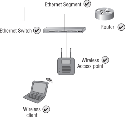
In addition to wireless infrastructure devices like access points, wired infrastructure components like Ethernet switches or Layer 3 routers can also be a potential source of global problems. Keep in mind that wireless client devices nearly always require a wired infrastructure in order to pass information between infrastructure devices or outside the wireless network. Devices and components that can contribute to wired infrastructure problems include:
- Ethernet cabling
- Ethernet switches
- Layer 3 routers
- Wide area network (WAN) connectivity
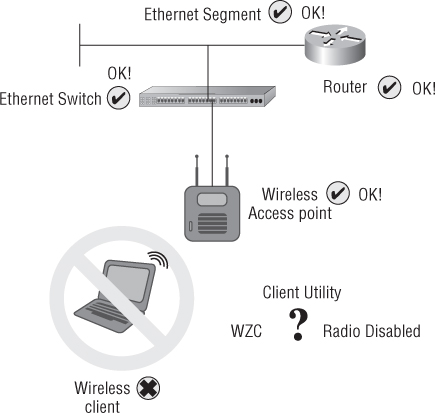
As shown in Figure 12.1, there are many components that can be the source of problems associated with wireless networking.
Figure 12.1 Many components, whether wired or wireless, can be the source of or contribute to wireless LAN problems.
Once it has been determined whether the problem is global or isolated, appropriate steps are necessary to determine the solution. But before we look at common problems associated with IEEE 802.11 wireless networking, it is important to understand a little more detail about how wireless LAN technology functions. This includes understanding the components used to send and receive radio frequency information and is accomplished by two main components:
- Radio frequency transmitter
- Radio frequency receiver
Radio Frequency Transmitters and Receivers
As discussed in previous chapters, IEEE 802.11 wireless networks use radio frequency to send and receive data. This is possible because all wireless devices have transmitter and/or receiver capability. Unlike a television or FM radio you may have in your home, both of which are only receivers, all IEEE 802.11 wireless LAN devices have the capability to act as either a transmitter or a receiver (also known as a transceiver). The following sections explain transmitter and receiver functionality in order to provide the groundwork necessary to diagnose and resolve IEEE 802.11 wireless networking problems.
Radio Transmitter
In wireless networking, a transmitter combines binary digital computer data (all of the 1s and 0s) with high-frequency alternating current (AC) signals to prepare it to be sent across the air. This is known as modulation. The connected antenna then transforms this signal into radio waves and propagates them through the air. The frequency of the signal depends on the technology in use. With IEEE 802.11 standards-based wireless networking, there are a few select frequency ranges.
Radio Receiver
A receiver collects the propagated signal from the air using an antenna and reverses the process by transforming the received signal back into an alternating current signal. Through the use of a demodulation process, the digital data is recovered. The modulation/demodulation technology used depends on the wireless standard or amendment with which the device is compliant. For example, an IEEE 802.11g wireless LAN will use 64QAM (quadrature amplitude modulation) when transmitting data at 54 Mbps. Figure 12.2 illustrates this entire process. Keep in mind that wireless LAN devices are transceivers, so they have the capability of performing either task. In this figure, the access point is the transmitter and the client device is the receiver. The details of modulation technologies are beyond the scope of the CWTS exam objectives and are not covered in this book.
Figure 12.2 sums up the entire process of IEEE 802.11 wireless LAN communications discussed throughout this book and is an introduction to understanding the process of troubleshooting.
Figure 12.2 A wireless access point (transmitter) and wireless client device (receiver) with computer data traversing the air using radio frequency

Wireless LAN Connectivity—Coverage and Capacity Problems
Many factors can cause connectivity problems in IEEE 802.11 wireless LANs. Wired computer networks use physical cabling to connect devices. This bounded medium is less likely to have connection issues unless the physical medium (cable) is damaged or broken. With wireless communications there is no bounded medium, because the air is what's used to carry the data using radio frequency.
No Wireless Connectivity
Several components of a network can cause connectivity issues with wireless networking. Keep in mind that wireless networks are not bound by a physical medium such as Ethernet cable; therefore, issues other than wiring may result in either no connectivity or intermittent connection problems.
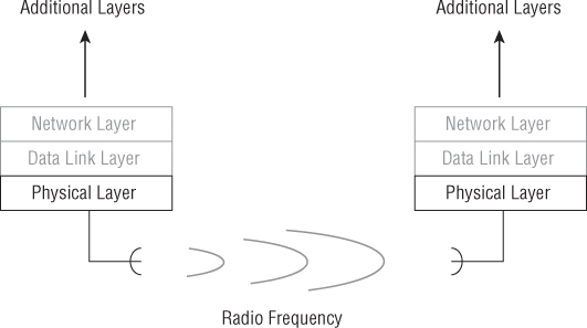
Let's review some of the OSI model information discussed in Chapter 1, “Introduction to Computer Networking.” The Physical layer provides the medium for connectivity (the air) in a wireless network and is used to carry radio frequency information that contains the computer data. This layer also includes components such as network adapter cards, which provide an interface to the wireless computer or other wireless device. Layer 1 connectivity provides the capability to transfer information that is sent between devices. Figure 12.3 illustrates the Physical layer and wireless connectivity.
Figure 12.3 The lower two layers of the OSI model are responsible for the operation of wireless networks. The Physical layer provides a connection between devices.
No Wireless Connectivity on the Client Side
IEEE 802.11 wireless networks require Physical layer connectivity in order to provide successful communications. This section describes some potential connectivity issues associated with client-side wireless devices. In many cases, no connectivity on the client side is an isolated issue that will not affect a large number of devices or users. Problems that can cause client-side lack of connectivity include:
- Disabled radio or wireless network adapter
- Misconfigured wireless client utility
- Microsoft Windows 7 AutoConfig service or the Windows XP Wireless Zero Configuration (WZC) not running or not configured
- Protective supplicants (wireless client device side) that can disable the radio in response to specific policy violations
A disabled radio or client adapter in a wireless client device can cause a lack of connectivity. Many devices, such as notebook computers, have physical switches or a combination of keys that can disable a radio. In many cases, a user does not even realize they turned off the physical switch for the wireless LAN radio. A disabled radio cannot provide RF communication between the client device and the wireless infrastructure, such as an access point. Figure 12.4 shows the icon for a disabled wireless adapter and the window explaining that the Microsoft WZC service is not started on a notebook computer with Microsoft Windows XP.
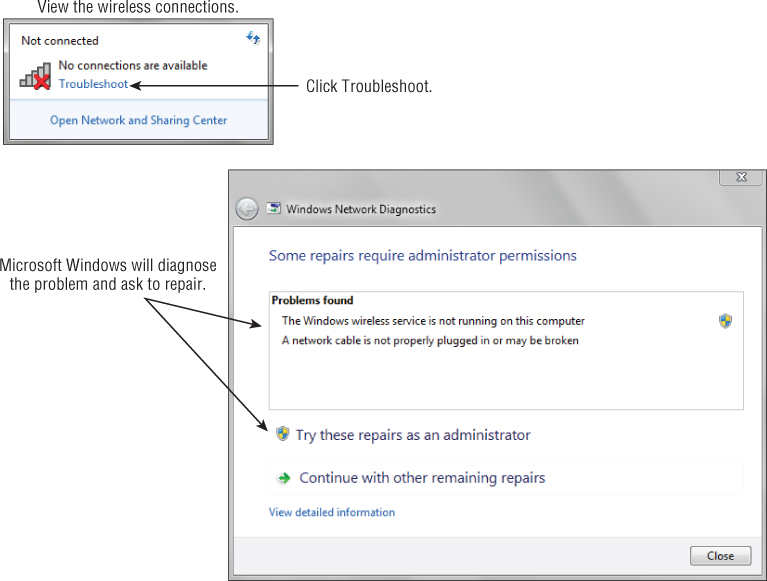
With the newer Microsoft Windows 7 operating system there are built-in diagnostics and troubleshooting that may help with some wireless LAN connectivity issues. Figure 12.5 shows the wireless connection dialog box as “Not connected.” If you click the Troubleshoot link, Windows 7 will go through a series of steps to try to resolve the issue. In this case the Windows wireless service was not running, and Microsoft was able to determine this and identified the problem.
If a client utility is misconfigured—for example, an incorrect SSID is specified—it would cause a lack of connectivity for the wireless client device. Client utilities have the capability to specify the SSID as a parameter. If the client does not see an access point with the specified SSID, it will not be able to connect to the IEEE 802.11 wireless LAN. This feature in a client device is often set by a selection to connect to a preferred SSID only by using a specific profile.
![]()
Figure 12.4 Disabled wireless LAN adapter and Microsoft Windows WZC service not running
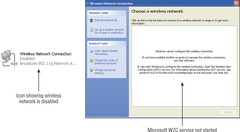
Figure 12.5 Microsoft Windows 7 wireless service not running and resolution using the built-in troubleshooting feature
The Windows built-in wireless client utility is a popular client utility for connecting to IEEE 802.11 wireless networks. The Windows wireless service (Microsoft Windows 7 AutoConfig service or Wireless Zero Configuration [WZC] for Windows XP) runs as a service or background process in the Microsoft Windows operating systems. If this service is not running or if the client device is not configured correctly to use Windows wireless services, the wireless client device will not be able to connect to the wireless network unless a third-party client utility from the adapter manufacturer is used. Figure 12.6 illustrates some of these potential issues from a wireless client device that may cause a lack of connectivity to the wireless network infrastructure.
Other Wireless Connectivity Issues
Connectivity issues can also arise if a misconfigured client utility has incorrect wireless LAN security settings or client IP address issues. Both will prevent a wireless client device from successfully completing the connection process and will prevent the transfer of computer data. Even though the Physical layer (Layer 1) and Data Link layer (Layer 2) connection may have been successful, the Layer 3 process would not be complete, and therefore data would not be transferred.
Figure 12.6 Devices and components that make up a wireless LAN showing potential wireless client-side issues
Before we discuss incorrect security settings further, it is important to have a better understanding of how an IP address (a logical address for a network interface) may have an impact on a successful connection and some of the issues associated with TCP/IP.
IP Address Connectivity Issues
Although wireless networks operate at Layer 1 and Layer 2 of the OSI model, Layer 3 and IP addressing also play a role because TCP/IP is used in most of today's computer networks. (Feel free to refer back to the discussion of the seven layers of the OSI model in Chapter 1.) Not long ago computer networks used various proprietary protocols to communicate with one another, such as Novell's IPX/SPX or Microsoft's NetBEUI. (A protocol is a set of rules that defines data communication between devices.) With the growth of local area networks, expanding to wide area networks and the World Wide Web (WWW) service, TCP/IP has become the standard protocol used in virtually all computer networks. Remember that Layer 3 and Layer 4 of the OSI model are responsible for addressing and routing both information and the session connection using the TCP/IP protocol. Figure 12.7 illustrates the two layers responsible for the TCP/IP protocol and the function of each.
Misconfigured IP address information can cause connectivity issues in an IEEE 802.11 wireless LAN. Most wireless networks, both SOHO and enterprise, have the capability to use Dynamic Host Configuration Protocol (DHCP). DHCP is a service that issues IP addresses and other TCP/IP parameters to connected computer network client devices. This service eliminates the need to manually assign logical Layer 3 IP addresses to all devices on the network. In IEEE 802.11 wireless networking, this DHCP service is provided directly from an access point, a wireless router, and a wireless LAN controller or from a server running DHCP services on the wired LAN. Many client device issues related to Layer 3 or above can cause failure to obtain a valid IP address. But this problem is often blamed on the wireless network even though a successful IEEE 802.11 authentication and association have occurred. Figure 12.8 shows an example of DHCP services using a wireless residential gateway/router.
Figure 12.7 Layers 3 and 4 of the OSI model are responsible for the addressing and routing of information as well as the session connection between devices.
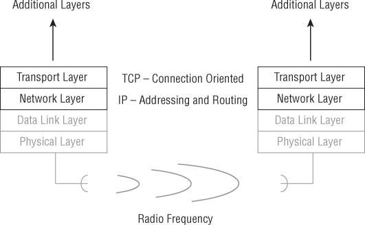
Figure 12.8 DHCP and IP address information from the ISP to the wireless client device
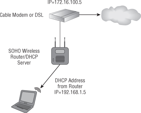
A cable or digital subscriber line (DSL) modem device connected to the ISP service will receive a DHCP address from the ISP. This modem will then issue IP addresses to wireless client devices or intermediary devices such as the IEEE 802.11 wireless router. If DHCP services are not running or are not operating correctly on the wireless router, the connected wireless client devices will not be able to obtain a valid IP address and will not be able to communicate above Layer 2.
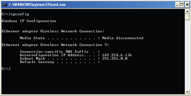
The computer operating system in use will determine what action the client device takes if an IP address cannot be obtained from a DHCP server. Windows uses a service that became available starting way back with Windows 98 and is now available in all versions of Windows, called Automatic Private IP Addressing (APIPA). APIPA is designed to provide an IP address automatically to any computer network device requesting one that is connected to a common LAN. APIPA does not require the use of a DHCP server. It also eliminates the need for users to manually set up IP addressing on all the devices. An APIPA address will be in the 169.254.X.X range. For example, a device such as a notebook computer may have an APIPA such as 169.254.100.20. If DHCP services are running on the LAN and a device cannot obtain an address from the server, or if DHCP services are not available, an APIPA will be issued. Figure 12.9 shows the ipconfig command displaying an IP address from Microsoft's APIPA.
Figure 12.9 Microsoft Windows APIPA
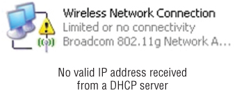
If a wireless access point or wireless router is connected to an IP subnet other than the one that uses automatic addresses, the wireless client device will require a valid IP address from the DHCP service in order to complete a network connection. If a valid IP address cannot be obtained from the DHCP service, the client will not have a valid TCP/IP connection to the access point or wireless router and instead will obtain an IP address from the 169.254.X.X range. This was much easier to identify in the Windows XP operating system. If this is the case, the wireless connection icon will show a “Limited or no connectivity” message and exclamation point, as shown in Figure 12.10.
Figure 12.10 Limited or no connectivity as the result of an IP address not being obtained from a DHCP server
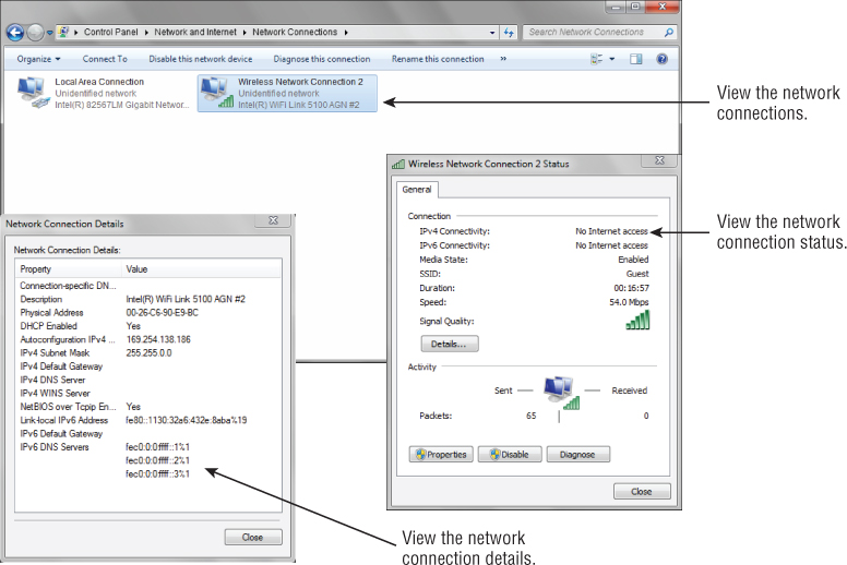
With the newer Windows 7 operating system you would need to look a little further to make the determination, as shown in Figure 12.11.
Figure 12.11 Windows 7 on a notebook computer with no IP address
![]()
Wireless Security Settings
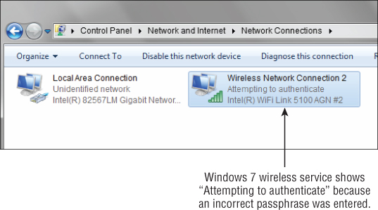
Incorrect security settings can also cause connectivity issues. Although you may get a physical Layer 2 wireless connection to the access point even with incorrect security settings on a wireless client device, you will not get a valid Layer 3 TCP/IP address from the DHCP server. For example, assume an access point is using WPA 2.0 personal mode for security. If a wireless client device has the wrong passphrase or preshared key entered, it will not complete the additional authentication that occurs after the IEEE 802.11 authentication and association process and will not have a valid Layer 3 TCP/IP address. In this case with the Windows XP operating system, the network adapter would stay in the “Acquiring network address” state; it would not be able to complete the Layer 2 connection process and would not receive a valid Layer 3 IP address. In the Windows 7 operating system the network adapter would show “Attempting to authenticate” in the network adapter status. Figure 12.12 shows an example of a wireless network adapter with the wrong passphrase set using the Windows 7 client utility.
Figure 12.12 The Windows 7 wireless adapter shows “Attempting to authenticate” when a wrong WPA passphrase is entered.
Intermittent Wireless Connectivity Problems
Intermittent problems of any type are often the most difficult to diagnose and repair. You may have had the experience of an intermittent problem with your car. For example, at a stoplight the car may start to idle roughly and stall. There is not really any rhyme or reason as to when this happens—it could be in the morning; it could be in the afternoon. You take your car to the mechanic for repair and of course the problem does not occur. Therefore the mechanic may have to keep your car for a period of time to try to duplicate the problem.
Intermittent problems with computers and networking are no different—they are difficult to diagnose if they can't be reliably reproduced. In many cases using a protocol analyzer to capture frames is invaluable. Frame traces will allow you to see what is happening between the wireless transmitter and the receiver. You learned about protocol analyzers for IEEE 802.11 wireless networks and their use in Chapter 11, “Performing an RF Wireless LAN Site Survey.”
Most intermittent connectivity issues in IEEE 802.11 wireless LANs are associated with the amount of received signal strength. If nothing else has changed (for example, a security setting or any type of device upgrade) and the wireless client device was working before, there is a good possibility the problem is associated with the amount of received signal.
Understanding the Received Signal Strength
One of the main concerns associated with IEEE 802.11 wireless networking is how much of the transmitted signal is identified as usable signal by the wireless client device. As mentioned in Chapter 11, this is known as the received signal strength indicator (RSSI) value. RSSI is an arbitrary number assigned by the device manufacturer. There is no standard for this value, and it will not be comparable between devices from different manufacturers. The calculation of the RSSI value is done in a proprietary manner, and a wireless device from one manufacturer may indicate a different received signal strength than that indicated by another, even though they both are receiving the exact same signal and at the same actual signal strength. This value is a key determinant of how well the wireless LAN device will perform. How the device is used with the network will determine the required levels of signal for optimal connectivity. Two wireless LAN client devices that are equal distance from the access point may display different RSSI values. Some client software utilities display this information in signal level bars to represent the amount of signal received. The more bars, the better the signal, whereas others may show the value in dBm. Wireless network engineers and support personnel should be able to know what the bars or numbers reveal and what they do not.
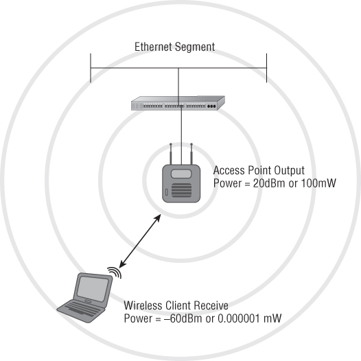
The actual recommended signal strength will vary based on the manufacturer, but some general numbers do exist. For example, in the 2.4 GHz ISM band, in order to get the maximum data rate, and depending on the application (either voice or data), some manufacturers recommend a range of –65 dBm to –67 dBm of received signal strength. Keep in mind, the closer the number is to zero, the better the received signal, and –65 dBm is closer to zero than –67 dBm. Figure 12.13 shows an example of an access point with an output power of 100 mW and the wireless client receiving a fraction of that amount, or 0.000001 mW. Although the wireless client device is receiving only a fraction of the transmitted power output, it is still able to move data at the highest data rate. Amazing!
Figure 12.13 Wireless client device receiving a fraction of the amount of power output by the access point
Testing the Received Signal Strength
So what does this mean? It means the lower the amount of radio frequency signal that is received by the receiver, the lower the data rate will be. As mentioned in Chapter 11, several tools are available that will allow a technical support specialist to see the received signal strength. These tools include:
- InSSIDer (free download)
- NetStumbler (free download)
- Wireless network adapter client utilities
- Spectrum analyzer utility
Any of these tools can be used to check the received signal strength by a wireless client device or at an end user's location to determine how much signal is being received, which will relate to the rate they should be transferring computer data.
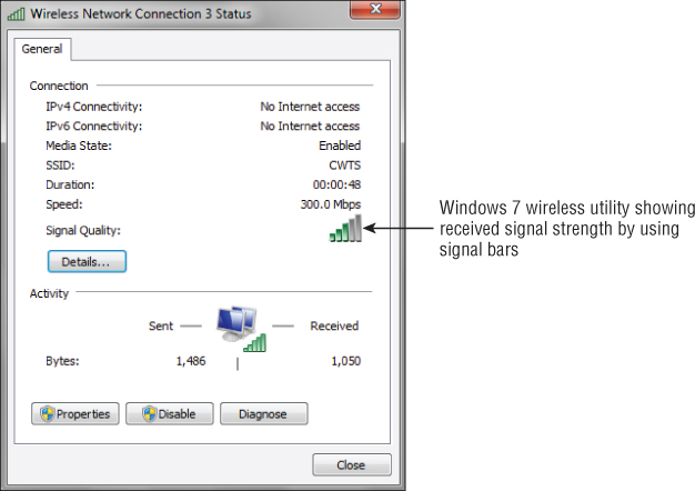
Figure 12.14 shows the Windows wireless service utility with bars representing the amount of received signal strength and the current data transfer rate.
![]()
Figure 12.14 Representation of received signal strength (signal quality) and data rate using the Microsoft Windows wireless client utility
Weak, Low, or No Radio Frequency Signal
Weak, low, or no radio frequency signal is typically an indication that the wireless LAN client device is too far away from a wireless access point or it is experiencing some level of RF interference. This could also be the result of some obstruction either blocking or severely attenuating the radio frequency signal. This is most often the result of a poor or nonexistent wireless LAN site survey or significant environmental changes. You learned about performing a wireless LAN site survey in Chapter 11. In order for a client device to operate correctly, the signal will need to be strong enough to connect to an access point and maintain the connection. A wireless client device will have a difficult time distinguishing between the RF signal and the RF noise if the signal level is too close to the noise floor.
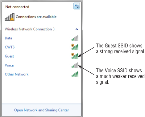
To review, the signal-to-noise ratio is the difference between the amount of received signal and the noise floor level in the area where the wireless client device is located. Chapter 11 discussed the noise floor and signal-to-noise ratio in more detail. Figure 12.15 shows the Windows 7 wireless utility and several wireless access points in the vicinity. Notice that the client device shows different received signal levels for the access points, as indicated by each one's number of bars. The Guest and CWTS SSIDs show a high received signal, but Data and Voice show only two bars, which represents lower received signal strength.
Figure 12.15 Microsoft Windows wireless client displays signal strength difference between nearby wireless access points.
Other wireless client utilities may show a more elaborate view of the signal strength and the noise level in an area. These are represented by dBm values rather than bar levels. In addition to client utilities, third-party utilities such as NetStumbler or InSSIDer will show received signal strength or noise levels, or possibly both.
Wireless LAN Throughput
Papa User says, “Someone's been taking my throughput!” Mama User says, “Someone's been taking my throughput!” Baby User says, “Someone's been taking my throughput and that someone still is!” Sound familiar? Receiving and maintaining enough throughput can be a tough chore in today's world of IEEE 802.11 wireless networking. Users just can't seem to have enough.
It is important to understand the difference between data rate and throughput. Throughput is the rate at which data is being transferred. It seems there is never enough to go around. When it comes to throughput, expectations are a key factor. It is important for users to realize that the actual throughput will always be lower than the advertised data rate. For example, in an IEEE 802.11n MIMO network the maximum data rate is theoretically 600 Mbps, but the actual throughput will be between 30 and 120 Mbps, much less than half of the advertised data rate. Keep in mind that these numbers will vary based on many factors, including the environment and the IEEE 802.11n technology features that are enabled.
Maximizing throughput is part of overall network design. A well-designed wireless LAN and site survey will yield excellent results. However, several factors may affect the throughput the users are receiving, including these:
- The wireless client device distance from an access point
- The radio frequency transmit output power of an access point
- The number of wireless devices associated to the access point
The Wireless Client Device Distance from an Access Point
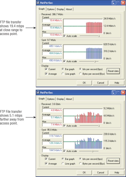
As we discussed earlier, as the wireless client's distance from an access point increases, the radio frequency received signal strength will decrease, thereby providing less average overall throughput. The type of wireless client device in use—computer, VoIP handset, handheld device, tablet, or barcode scanner—will determine the acceptable levels of data throughput. Most wireless client utilities will show that the expected data rate is based on the received signal strength. It is important to remember that the expected data rate is not actual throughput. Figure 12.16 illustrates this point by showing two different throughput sessions, both connected to the same access point. Session 1 is in close proximity, about 15 to 20 feet from the access point. Session 2 shows the throughput at a greater distance, about 45 feet from the access point.
Figure 12.16 Two FTP file transfer sessions showing the difference in throughput based on distance from an access point
The Radio Frequency Transmit Output Power of an Access Point
The amount of radio frequency transmit output power being sent from the wireless access point will also determine RF signal strength for the connected wireless client devices. This is because the higher the RF power, the farther an RF signal will travel or propagate. If a wireless client device is receiving a low RF signal and adding an additional access point is not an option, increasing the output power of the access point may do the trick. However, keep in mind that this needs to be evaluated closely.
If a physical wireless RF site survey is performed, I recommend that you have the access points set to less than the full available transmit output power. What the transmit output power level is set to during a site survey will depend on the engineer who performs the survey or the manufacturer recommendations. If an access point is not set to full power, it will be possible to make adjustments to compensate and potentially correct problems such as a wireless client device experiencing low throughput because of a low received signal strength value.
The Number of Wireless Devices Associated to the Access Point
Because wireless LANs use the air as a shared medium, the more wireless client devices that associate to the wireless access point, the less throughput each device will be able to receive. The type of hardware can also affect the throughput based on the number of associated users. For example, if 25 users are associated to an access point using wireless barcode scanners that typically transfer small amounts of information, they may have better performance than 5 users using bandwidth-intensive applications such as CAD/CAM on notebook computers. Load balancing of devices between access points can help limit the number of associated wireless client devices. Co-channel interference can cause the same issue, because wireless devices on the same or a close channel, associated or not, are part of the same contention domain.
Solutions to Low Wireless LAN Throughput
There are several possible solutions to low throughput problems clients may be experiencing. The appropriate solution will depend on the specific situation. If an RF site survey was performed correctly and thoroughly, additional access points should not be needed unless there have been environmental or capacity changes in the area since the original survey was performed. Solutions to low-throughput problems include the following:
- Adding more access points
- Increasing output power of access points
- Increasing antenna gain
- Enabling load-balancing solutions on access points
One or more of these solutions may help increase the throughput for users connected to a wireless network. Figure 12.17 shows a before-and-after scenario based on output power of an access point.
Of the solutions just discussed, none is always better than the others. Which solution you choose is going to depend on several factors, including the number of wireless client devices, the number of access points, budget constraints, and potential interference issues.
Figure 12.17 Increasing the output power of an access point will provide higher received signal strength for the client, resulting in better overall throughput.

![]()
Application Performance Problems
As you now know, IEEE 802.11 wireless networks are a major part of every computer network in all industries and homes. Many different types of applications, both software and hardware, want to take advantage of the wireless network capabilities. Therefore it is important to understand the various types of applications your IEEE 802.11 wireless LAN may use and how to prevent problems that can arise from the use of these applications. Some of the common applications that are used via wireless LANs are:
- Application servers for user software, such as word processing
- Databases
- Engineering applications, such as computer-aided design
- File servers for storing data
- Barcode scanners
- Printers
- Voice handsets
This is not a complete list, but for the most part every resource or application that is used in the wired network is also a candidate for the wireless network. Many of the problems that you experience with a wired network will be even more common on a wireless network. We have all the same potential problems as we do in a wired network, but more because it is wireless. Remember that IEEE 802.11 wireless LANs use a shared medium (the air) and are contention based, which will create both interference and capacity problems. Using the appropriate tools such as a wireless packet analyzer and radio frequency spectrum analyzer will help to identify and resolve these problems. The following sections describe how to identify and resolve these problems.
Wireless Device Software and Hardware Upgrades
Software and hardware upgrades play a role in the maintenance and support of any wireless LAN deployment. Having the latest device drivers or software client utilities will help improve performance and solve problems associated with software-related issues. Firmware also needs to be updated periodically to ensure the latest and greatest fixes, and new features are applied to the devices such as access points or wireless LAN controllers.
Client Device Software Upgrades
Upgrading the software related to wireless LAN technology has many benefits that may help resolve performance or operation issues. Technical support or network engineers should find time to stay up-to-date with the latest software versions available for the hardware in their network. This can be done by looking at the manufacturer's website or subscribing to a service that will announce changes and updates. Software upgrades for wireless networks commonly fall under three areas:
- Device drivers
- Client device adapter utilities
- Device firmware
Software upgrades on any of these components will help enhance the performance of the client devices. These upgrades can come as a fix for a problem with the software or potentially provide new features for a client device. In Chapter 4, “Wireless LAN Client Devices,” you learned about some of the software components required that will enable a client device to connect to an IEEE 802.11 wireless network. This section focuses on the process of upgrading the software associated with these devices.
Device Drivers
Device drivers are the software components that allow a hardware device to function with a computer operating system. This is accomplished by the software providing an instruction set for all devices that connect to a computer, tablet, handheld, or any other device that runs with an operating system. The following list is a sampling of the devices that will require a software device driver:
- Hard drive
- Video card
- Keyboard
- Mouse
- USB ports
- Network adapters
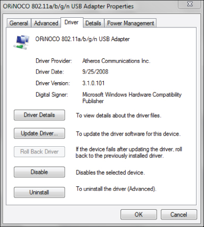
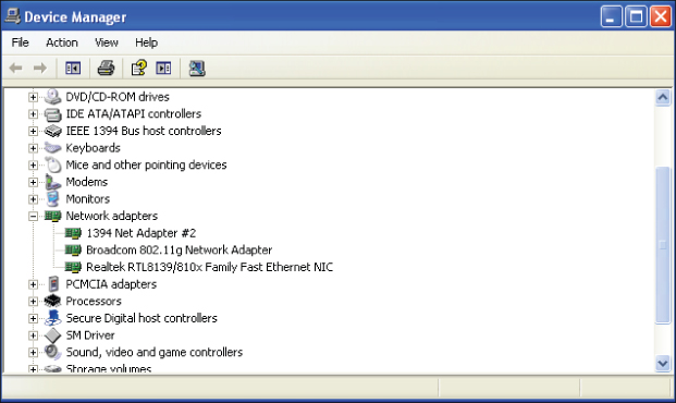
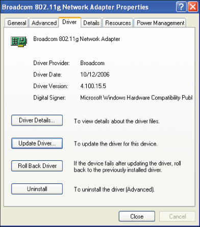
With wireless networking, the device driver that is of most concern is the one used for the wireless network adapter. This adapter is what allows a computer or other client device to connect to a wireless network in either infrastructure or ad hoc mode. Figure 12.18 shows an example of viewing the device driver properties for a wireless network adapter in the Windows 7 operating system.
Figure 12.18 Device driver information in Windows 7 for an ORiNOCO IEEE 802.11a/b/g/n USB wireless network adapter
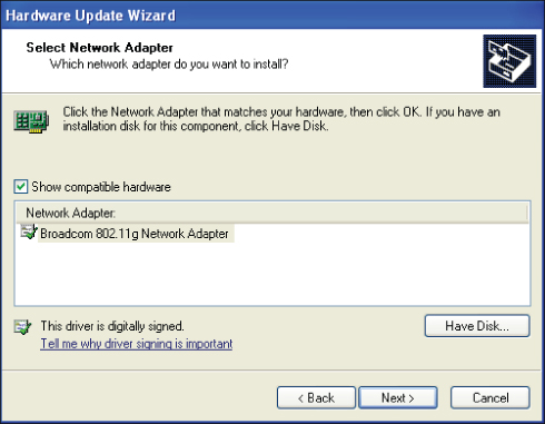
In addition to causing intermittent connectivity problems, device drivers may become corrupt and prevent the device from starting up correctly. They can even cause operating system startup problems. With today's sophisticated computer operating systems and features, such as plug-and-play, having to worry about the physical settings of a device is less common than it was a few years ago. Upgrading or replacing a device driver in Windows operating systems is a fairly straightforward process. Exercise 12.1 will step you through upgrading a device driver for your wireless network adapter.
Client Device Adapter Utilities
Client adapter utilities may need to be upgraded occasionally. By upgrading the client adapter utility, you will usually add new features or settings to enhance the performance and function of the utility.
The Windows wireless utility is usually upgraded either from a service pack or a hotfix available from the Microsoft website.
Device Firmware
Device firmware is the instruction set that allows hardware to operate based on its design. Firmware is simply software that remains in memory when the power is removed. Firmware tends to be hardware oriented, but not all firmware involves the control of hardware. Many Layer 7 user interfaces and agents are implemented as firmware burned into read-only memory devices (ROMs).
Conversely, there are many examples of software directly controlling hardware. Most drivers for hardware devices are software (loaded into volatile memory only when power is present) and not firmware (always resident in static memory regardless of power). Firmware upgrades are common support tasks that need to be done periodically, either to fix issues with the way the hardware is operating or to provide new features for the hardware.
All infrastructure devices, either SOHO-grade or enterprise-grade, allow you to upgrade the firmware. In enterprise environments, firmware upgrades can be performed either manually or automatically with the aid of a wireless LAN management system software or appliance.
![]()
Most infrastructure devices have several options for performing upgrades. These upgrade options include:
- Hypertext Transfer Protocol (HTTP)
- Trivial File Transfer Protocol (TFTP)
- File Transfer Protocol (FTP)
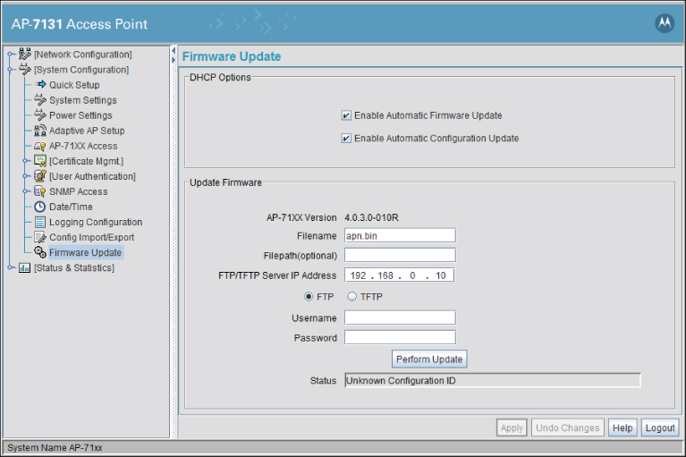
Figure 12.19 shows an example of a graphical user interface (GUI) screen where a firmware update is being processed.
![]()
- Always verify that you have the correct firmware file for the device to be upgraded prior to performing the upgrade.
- Always read the release notes that come with the firmware.
- Never upgrade firmware on a device that is running on battery power.
- Never power down the device while the firmware upgrade is in process.
Figure 12.19 Motorola AP7131 wireless access point firmware update screen
The firmware in enterprise-grade access points and wireless controllers can usually be upgraded using the command-line interface instead of the GUI if desired.
Wireless Infrastructure and Client Device Hardware Upgrades
There may be various reasons to upgrade hardware for both infrastructure and client-side devices. Hardware upgrades are a part of the ongoing maintenance process with all networking devices, including wireless LANs.
Wireless Infrastructure Devices
Upgrading wireless infrastructure devices can be an expensive and time-consuming task. Justifying these infrastructure device upgrades may require preparing reports that include performance of the wireless LAN infrastructure and client devices as well as documentation that shows how an upgrade will enhance the end-user performance and make users more productive in their job functions.
Upgrading wireless infrastructure devices such as access points can give an organization the ability to enhance the performance of the wireless network by increasing the speed or reliability of the wireless LAN. The hardware currently in use helps determine the extent of an upgrade. Some upgrades may only require the installation of a new or additional radio. Some access points are modular and provide this capability. One example of a wireless infrastructure upgrade is moving from IEEE 802.11b/g to IEEE 802.11n and MIMO technology.
Antennas
Unless the physical characteristics of the area where the wireless LAN is deployed have changed since the site survey, chances are that antennas will not need to be upgraded. If characteristics such as additional walls or types of furnishings or other physical attributes have changed, antennas with different propagation patterns or higher gain may be required. Another situation where antennas may need to be upgraded or changed is if the initial site survey was not performed thoroughly or correctly. In some cases where external antennas are used on an access point, they may have been struck and accidentally moved, changing the polarity. A physical inspection of the deployed infrastructure devices should be part of routine wireless LAN administration or support to locate and correct such issues.
Wireless Client Device Upgrades
Client device upgrades can be automatic if the technology refresh for devices has taken place. For example, if a company replaces 50 notebook computers with newer models, the new notebooks will probably have wireless LAN adapters that are capable of IEEE 802.11a/b/g/n. The capabilities of these new notebooks may be more advanced than the wireless infrastructure that is currently deployed.
Another situation where wireless client devices may need upgrading is one in which the infrastructure changes to different hardware or technology. If a company upgrades access points from IEEE 802.11b/g to IEEE 802.11n and the clients only support 802.11b/g, the client devices may need to be upgraded in order to take full advantage of the new IEEE 802.11n wireless infrastructure.
Optimizing Wireless Networks
Making changes to an IEEE 802.11 wireless LAN installation may be required in order to provide optimal performance for the devices that will be connecting. In some cases, a wireless LAN site survey is considered an ongoing process due to the dynamics of radio frequency and changes in technology. This being the case, an existing wireless LAN deployment may have to be resurveyed to provide optimal performance for the users. Here are some of the factors that you need to consider when optimizing a wireless LAN:
- Wireless infrastructure hardware selection and placement
- Radio frequency interference sources
- Client device load balancing
- Access point capacity and utilization
- Minimizing multipath
- Understanding hidden node problems
Wireless Infrastructure Hardware Selection and Placement
Wireless infrastructure hardware selection and placement are typically part of the wireless LAN site survey process. However, occasionally you may need to reevaluate after the wireless LAN has been installed. Although the objective of a site survey is to design the network, find locations and sources of interference, and decide on locations for infrastructure devices, you may have to make some adjustments to allow for optimal performance. These adjustments may include minor relocation of access points as well as radio frequency adjustments, including channel and output power settings. These adjustments would ensure that clients have maximum signal strength, throughput, and roaming capabilities. Applications—both hardware and software—and user requirements could also change, requiring an optimization or resurvey of the wireless network.
Identifying, Locating, and Removing Sources of Wi-Fi and Non-Wi-Fi Interference
In Chapter 11, we discussed how to identify areas of radio frequency coverage and Wi-Fi and non-Wi-Fi interference. This usually is part of the wireless LAN site survey process. The best way to identify sources of interference is with a spectrum analyzer. This could be in the form of an instrumentation device or a PC card–based spectrum analyzer designed specifically for wireless networking.
During this wireless site survey process, interference sources should be identified. However, changes to the environment may introduce new sources of RF interference. Also, keep in mind that a walkthrough spectrum analysis of an area will only record the RF it sees at that instant in time. If a new piece of equipment is introduced into an area, it may cause interference with the wireless network that would not have been present during the RF site survey spectrum analysis process. Businesses or organizations that use wireless LANs where this could be a factor include:
- Healthcare deployments
- Warehouse/retail deployments
- Manufacturing deployments
- Industrial deployments
Therefore, an ongoing spectrum analysis may be required to identify and if possible remove the sources of interference. If these new sources of interference are there to stay, it will be necessary to make appropriate adjustments for the network to operate as designed. The number one source of interference in a wireless network is other wireless devices.
![]()
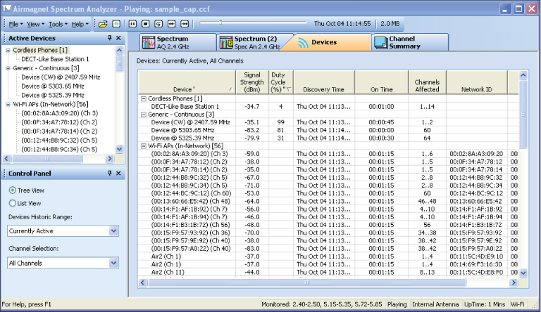
Figure 12.20 shows an example of a PC card spectrum analyzer that can be used to perform a spectrum analysis to help locate new sources of RF interference after a wireless LAN has been deployed.
Figure 12.20 AirMagnet Spectrum Analyzer showing devices that may cause RF interference
Wireless Client Device Load Balancing and Infrastructure Device Redundancy
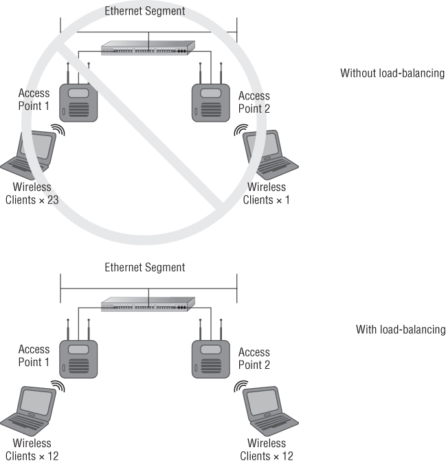
Client load balancing is a mechanism that prevents wireless client devices from associating to an access point that has already reached the maximum number of client devices for optimal performance. There are a variety of ways this can be accomplished, typically proprietary to the manufacturer. Parameters for load balancing can be set on the access points, wireless LAN management software, or wireless LAN controllers. Load balancing will allow optimal use of all access points in a specific area by preventing too many devices from connecting to a single access point and overloading the access point, which in turn would cause poor performance for all associated devices. Band steering in now implemented by many wireless equipment manufacturers. Band steering will attempt to get wireless client devices that are 5 GHz capable to use the 5 GHz band rather than the 2.4 GHz band. Figure 12.21 illustrates the load-balancing process for wireless LAN access points.
Figure 12.21 Load balancing ensures optimal performance for connected wireless client devices.
The ways in which load balancing is implemented depend on the manufacturer of the wireless LAN equipment. One solution is a settable parameter in an access point specifying a maximum number of devices allowed to connect at any one time. Once the access point has reached its capacity, a client device wanting to associate will be presented with an error message and will not be allowed to complete the process. Some manufacturers will direct the wireless client device to an access point that will be able to accept the connection rather than deny the connection.
Wireless Infrastructure Device Redundancy
Designing for wireless LAN redundancy is an important factor in most enterprise wireless LAN deployments. In both wireless LAN controller-based implementations and wireless access points implementations, it is critical to eliminate any potential single point of failure in the wireless LAN.
Analyzing Wireless Infrastructure Capacity and Utilization
It is important to have a baseline for the performance of your wireless LAN. This baseline will show the average utilization and capacity of the connected infrastructure devices at various times during the company's business hours. Continuous monitoring of the wireless network is similar to that of a wired network. Performance metrics will be needed to gauge the use of the wireless LAN and infrastructure devices and show how well the system performs. These metrics will also show areas that are lacking in performance, including bottlenecks or overutilized access points. Using these performance metrics will show which infrastructure devices need attention. This may include moving or adding access points for additional capacity or to allow for higher utilization. Changes to the environment, such as the addition of users, may justify the need for additional access points.
![]()
Radio Frequency Performance Problems: Multipath
With IEEE 802.11 a/b/g systems, poor throughput can be the result of corrupted data, which may be caused by multipath. Multipath is various radio frequency wavefronts of the same signal being received at slightly different times. Multipath is caused by RF reflections based on the physical attributes where an access point is placed. As discussed in Chapter 7, “Wireless LAN Antennas and Accessories,” antenna diversity will help minimize the problems for IEEE 802.11a/b/g systems caused by multipath.
It is important to understand that although multipath is a hindrance in most IEEE 802.11a/b/g wireless LAN implementations, it is beneficial for IEEE 802.11n systems. MIMO technology used with 802.11n is designed to take advantage of multipath and increase throughput by using the effects of multipath as an advantage. You learned in Chapter 5, “Physical Layer Access Methods and Spread-Spectrum Technology,” that unlike IEEE 802.11a/b/g SISO systems, IEEE 802.11n MIMO access points use multiple radios with multiple antennas. The multiple radio chains and some additional intelligence are what give 802.11n MIMO access points the capability to process reflected signals. Since MIMO works with both the 2.4 GHz ISM and 5 GHz UNII bands, a dual-band IEEE 802.11n MIMO access point will have up to six radio chains—three for 2.4 GHz and three for 5 GHz—and six antennas (one for each radio) for data rates of up to 450 Mbps. IEEE 802.11n MIMO technology allows for up to four radio chains, which in turn would provide up to 600 Mbps. However, very few manufacturers are providing four radio chains.
If you are experiencing performance problems where multipath may be a potential issue, you will need to evaluate your environment to determine if this is contributing to the issues. Using the proper diversity technology for IEEE 802.11a/b/g systems and upgrading to IEEE 802.11n systems are some of the options. If you are using diversity-capable access points with integrated antennas, spacing between antennas will be correct. If you are using external antennas, keep in mind that the spacing between the antennas should be in multiples of the wavelength for the frequency that is used. Check with the manufacturer of the access points you are using to determine how diversity antennas should be installed.
Radio Frequency Performance Problems: Hidden Node
More IEEE 802.11 wireless LAN installations experience hidden node problems than you would probably imagine. Hidden node is the result of wireless client devices connected to an access point and not able to “hear” each other prior to starting a transmission. This will result in collisions at the access point and the loss of data. As discussed in Chapter 5, the CSMA/CA process is designed to avoid collisions between devices sharing the same medium. This process includes the use of a mechanism called clear channel assessment (CCA). CCA detects radio frequency energy from other IEEE 802.11 wireless client devices in the same RF space and understands that the medium is busy. Therefore, that wireless client device will not attempt to transmit until it detects the medium is clear.
Three causes of the hidden node problem are:
- Hidden node obstacle (obstructions)
- Hidden node distance (signal strength)
- Hidden node technology (signaling methods)
There are both hardware solutions and software solutions to resolving hidden node problems. The following sections describe hidden node problems and solutions in more detail.
Hidden Node Obstacle or Obstruction
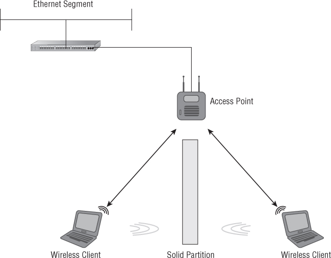
Hidden node obstacle is caused by two or more client devices connecting to an access point in which access point–to–client device RF communication is clear but client device–to–client device RF communication is blocked. Figure 12.22 illustrates an example of hidden node obstacle.
Figure 12.22 Hidden node caused by an obstacle or obstruction
There are several physical solutions to the hidden node obstacle problem. Any of these solutions should allow for the correct RF communication between access points and wireless client devices. Some of the physical solutions to hidden node obstacle include the following:
Hidden Node Distance or Signal Strength
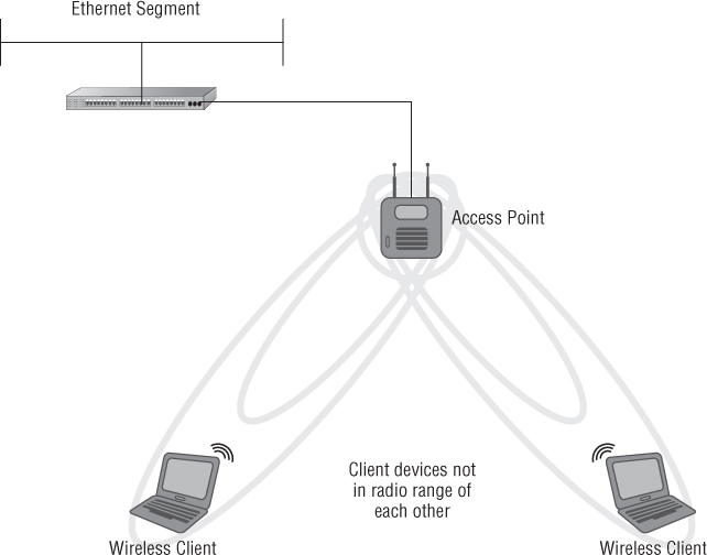
With hidden node distance or hidden node signal strength problems, client device–to–client device RF communication cannot occur because the client devices are too far apart and not in radio range of each other. However, access point–to–client device RF communication does take place, because these devices are within radio range. Figure 12.23 shows an example of hidden node distance.
Figure 12.23 Hidden node as a result of distance between wireless client devices
Just as in hidden node obstacle problems, physical solutions exist for the hidden node distance problem. These physical solutions provide adequate RF communication for access point–to–wireless client device and for client device–to–client device. The following are examples of solutions for hidden node distance:
Hidden Node Physical Layer Technology or Signaling Methods
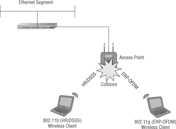
Hidden node technology problems occur when access points experience excessive collisions because of different spread spectrum or Physical layer communication technologies that are sharing the same RF medium. This can happen when, for example, an access point has to share transmissions between 802.11b (HR/DSSS) and 802.11g (ERP-OFDM) client devices. Figure 12.24 illustrates the hidden node problem due to different Physical layer technologies in use.
In this example the only physical solution to the hidden node technology problem is to allow either 802.11b or 802.11g devices to communicate with the access point but not both. In most cases, this is not a realistic solution, because allowing only one of the technologies to communicate with an access point prevents devices using the other technology from using the network. In other words, giving only 802.11g (ERP-OFDM) devices the capability to use the network would prevent 802.11b (HR/DSSS) devices from using the network resources, or vice versa.
IEEE 802.11n, the newest communication amendment and now part of the IEEE 802.11-2012 standard, consists of four protection modes. The same potential hidden node problems will exist with 802.11n devices but even more so because 802.11n is capable of operating in both the 2.4 GHz ISM and 5 GHz UNII bands. These modes are known as High Throughput (HT) protection modes and are a set of rules client devices and access points will use for backward compatibility. You learned in Chapter 8, “Wireless LAN Terminology and Technology,” that these modes are constantly changing based on the RF environment and associated wireless client devices.
Figure 12.24 Hidden node based on technology types such as HR/DSSS and ERP-OFDM
The Software Solution to Hidden Node Problems
There is a software configuration solution for all of the hidden node problems just described. This software configuration solution is known as a process called request to send (RTS), clear to send (CTS), or RTS/CTS. The RTS/CTS process allows devices to reserve the medium for a specified period of time, enabling a device to complete a frame exchange and avoid collisions. RTS/CTS frames are also used with protection mechanisms to allow different IEEE 802.11a/b/g/n technologies to interoperate. You learned about protection mechanisms and Mixed Mode in Chapter 8. The RTS/CTS process was discussed briefly in Chapter 8 but is beyond the scope of the CWTS exam objectives and therefore is not discussed in detail.
Summary
In this chapter, we looked at troubleshooting and maintenance concerns that may involve wireless networking. This included identifying wireless LAN problems as both global (many) and isolated (individual) and the process for troubleshooting these problems. Global problems may include wireless infrastructure devices, such as:
- Wireless access points
- Wireless bridges
- Wireless LAN controllers
Isolated problems usually include a single wireless LAN client device or computer that could be experiencing connectivity or data transfer issues. We also looked at basic radio frequency communications using a transmitter and receiver and how these devices operate in a wireless LAN. We examined connectivity issues, including no connectivity or weak connectivity, and the problems that can be associated with connectivity issues. No connectivity on the client side could be something as simple as a network adapter not enabled or could be related to something more in depth, including:
- Upper layer TCP/IP issues
- Security configurations
In this chapter, you learned about received signal strength and the difference between a strong signal and a weak signal, as well as some of the reasons why a wireless client device may experience weak or no signal. Throughput is another area we explored that involves client-side performance. We discussed some of the factors that could cause low throughput and how to solve these issues.
Upgrading software is another area that needs be taken into consideration with wireless LANs from the client side, upgrading device drivers or client software utilities, as well as the infrastructure side, which includes upgrading firmware. All of these areas are important parts of wireless LAN maintenance and support.
Finally, you saw how to optimize wireless networks and some of the areas that should be considered for this optimization, which may include making the necessary adjustments from the original wireless site survey. These adjustments could be a result of changes to the environment such as walls, doors, windows, or other physical attributes of the location. Other important factors include client load balancing, multipath, and hidden node issues.
Exam Essentials
Review Questions
1. In wireless networking, multipath is the result of what RF behavior?
A. Refraction
B. Diffraction
C. Absorption
D. Reflection
2. A wireless client device is showing a low receive signal strength value. What option could improve this situation?
A. Upgrade the client device
B. Add another access point
C. Upgrade firmware on devices
D. Eliminate multipath
3. You recently installed an IEEE 802.11g wireless network in a small office. One of the employees has been complaining of poor performance and mentioned her notebook computer runs very slowly because of the access point it connects to. What could cause this notebook computer to be performing poorly?
A. The new 5.8 GHz cordless telephone in her office is interfering with the IEEE 802.11g wireless LAN.
B. The access point is located at the opposite side of the building from the user's office separated by several walls.
C. A media access control (MAC) filter is enabled on the notebook computer, causing excessive retries.
D. You recently rolled out a new version of the access point's firmware to enable new features that became available.
4. The RF signal strength seen by a wireless client device from an IEEE 802.11n access point can be improved by .
A. Increasing the output power on the access point
B. Enabling load balancing
C. Upgrading the ISP service
D. Enabling WPA 2.0 on both the access point and the client
5. You are a help desk technician providing support for a wireless network. A user calls and complains he cannot access the Internet. The user tells you he has good signal strength, but the network connection states “acquiring network address” and the IP address is all zeros. What could cause this problem?
A. The client device has a static IP address.
B. The client has an 802.11a network adapter.
C. There is an incorrect WPA passphrase on the client device.
D. A computer virus has infected the client device.
6. You provide consulting services for various companies and receive a call from one of your clients that their notebook computers suddenly started experiencing slow data transfers from the wireless LAN. This company is located in a multitenant building. What could cause a sudden change in performance for the notebook computers?
A. A firmware upgrade was recently performed on the access point.
B. The access point for a new tenant in the building is set to the same RF channel.
C. The access point shows a low received signal strength.
D. Someone activated the diversity antennas on the access point.
7. What can solve a hidden node problem caused by an obstacle or obstruction on an IEEE 802.11g wireless network?
A. Adding another access point
B. Setting the access point to Mixed Mode
C. Increasing the distance between the access point and the clients
D. Adjusting the received signal strength on the client
8. Weak signal strength would have an impact on what device?
A. Infrastructure device
B. Client device
C. Multipath device
D. Transmitter device
9. An incorrect passphrase set on a client device will result in a different preshared key that is generated for a device using WPA 2.0 as a security solution. What will be the result of a mismatched passphrase between the client device and an access point?
A. Association is established and terminated and no valid IP address
B. Invalid association and valid IP address
C. A deauthentication
D. A disassociation
10. The throughput of a wireless LAN can be affected by or .
A. Distance from access point, IP address
B. Distance from access point, MAC address
C. Distance from access point, output power of access point
D. Distance from access point, output power of client device
11. The device driver of a wireless network adapter card is .
A. Required
B. Optional
C. Used with security
D. Another name for SSID
12. What is a valid solution to a hidden node problem caused by different technology types?
A. Mixed Mode technology
B. Additional access point
C. Increasing output power
D. Removing an obstacle
13. You are a network administrator and receive a call from a user stating that she cannot access the wireless LAN. The office contains 50 other users, and nobody else is complaining about the network. What could be a potential problem that would keep this user from connecting to the access point?
A. The connection to the Internet has been terminated.
B. The access point needs to be upgraded.
C. Incorrect firmware was installed on the access point.
D. The wireless client device has a corrupt device driver.
14. Lack of RF connectivity on a wireless client could be caused by which layer of the OSI model?
A. Layer 1
B. Layer 3
C. Layer 4
D. Layer 7
15. What address would be considered a Windows Automatic Private IP Address, assigned when no DHCP server is available on the LAN?
A. 192.168.0.1
B. 172.168.0.1
C. 169.254.0.1
D. 10.1.0.1
16. Weak or no signal at a wireless client device can be the result of .
A. Distance from an access point
B. Distance from other client devices
C. Distance from the wiring closet
D. Distance from Ethernet switch
17. What does the signal-to-noise ratio represent?
A. The difference between output power and noise floor
B. The difference between received signal and noise floor
C. The difference between access point output power and received client power
D. The difference between client output power and noise generated by the access point
18. What can IEEE 802.11n MIMO technology use to provide higher throughput to wireless client devices that 802.11g cannot?
A. Hidden node
B. Received signal strength
C. DHCP
D. Multipath
19. The throughput of a wireless LAN client device can be increased by performing which task?
A. Adding access points
B. Upgrading the client software to full-duplex mode
C. Increasing the RF noise
D. Hiding the SSID
20. The received signal strength of a wireless client could be increased by .
A. Upgrading the wireless client device
B. Enabling load-balancing features on the access point
C. Increasing the gain of the antenna on the access point
D. Installing the Microsoft Wireless Zero Configuration utility