
Chapter 5: Virtualizing Networks with VLANs and VTP
In This Chapter
![]() Understanding VLANs
Understanding VLANs
![]() Configuring VLANs
Configuring VLANs
![]() Easing management of VLANs with VTP
Easing management of VLANs with VTP
Once upon a time not so very long ago (cue: sparkly sounds of a fantasy, animated movie opening sequence), in order to separate users into individual network segments for security or other reasons, you had to provide them with their own network switch. If these users were in separate areas of your office, going to separate wiring closets, you also had to give them a separate cable for uplink or backhauling between wiring closets. This process created a ton of extra work and quickly became annoying.
Enter virtual LANs (VLANs): a solution to fix these ills. In this chapter, I show you how to set up VLANs, as well as how to automate the process of propagating VLAN information among your switches, which can quickly turn into work. I then show you how to implement trunk links among the switches, which is the easiest way to interconnect switches supporting the configured VLANs. Finally, I discuss VLAN configuration and implementing VLAN Trunking Protocol (VTP) to make VLAN management easier. Although you can manage VLAN deployment without VTP, using it does diminish the legwork on large networks, and by the end of this chapter, you will be able to lay out a simple network deployment with VLANs and VTP.
Implementing Virtual Local Area Networks (VLANs)
With the cost per port for switches following the same economies of scale as most other items in the world, it makes sense to purchase switches with the highest port count — so to save money, get one 48-port switch rather than two 24-port switches. But what about those four users who need to be isolated from everyone else? If you have a standardized switch model used in your organization, you may be forced to get those users another 12-port or 24-port switch in the same series and, of course, wasting the additional ports. I would if I were not using a managed switch that supports VLAN technology.
By using VLANs, you can take four ports on one switch and associate them with a VLAN, which means you treat those four ports as their own separate switch. Doing so allows you to isolate them and save money on a new hardware purchase. Even better, by being careful with VLAN and port assignments, those four ports do not need to be on the same switch or in the same wiring closet, because you can interconnect all the ports belonging to a single VLAN over inter-switch links that have been configured for Trunk mode. A port configured for Trunk mode is also called a trunk port and, by default, it will pass traffic for all VLANs. You will hear about trunk ports throughout this chapter.
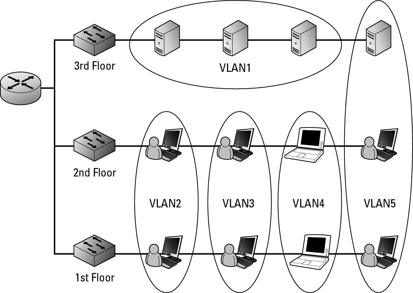
In short, VLANs allow you to break up devices on your network regardless of their location. Figure 5-1 illustrates separating users’ computers and servers into functional groups. The servers are isolated in VLAN1; VLAN5 is a department with its own departmental server; and VLAN2, VLAN3, and VLAN4 separate users into functional groups, say sales, finance, and manufacturing. Each device can operate on their own VLAN regardless of the location they are connecting on the network. In most cases, these devices are spread over the switches in some manner, but they could also reside all in one location (like the servers do).
Figure 5-1:
A typical VLAN infra-structure.
You now know that you can break up your network into smaller virtual chunks. If you want to know how this all works in the end, keep reading.
Understanding how VLANs work
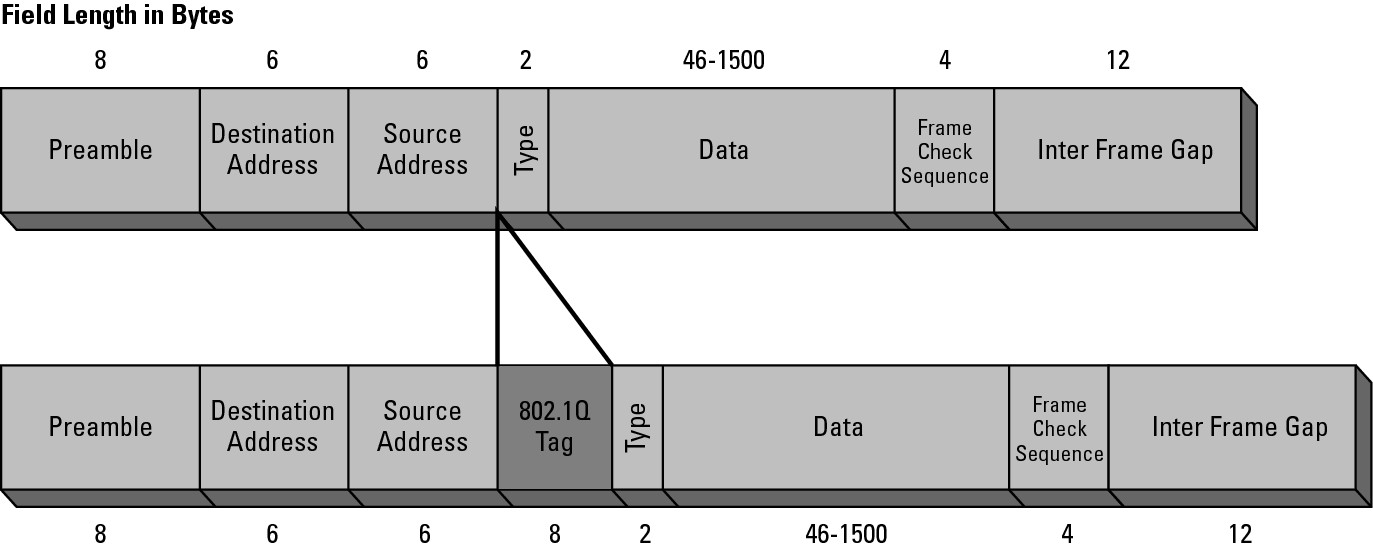
The magic of VLANs is found in the Ethernet headers. When a switch receives an Ethernet frame, the frame will either already have a VLAN tag or the switch will insert a VLAN tag into the Ethernet header. If the frame was received from another switch, that switch will have already inserted the VLAN tag; while frames come from network devices, such as computers, the frame will not have a VLAN tag. If you are using the switch defaults for VLANs, the VLAN tag that will be placed on the frame is VLAN1. Book I, Chapter 4, covers the basic structure of the frame, but not where the VLAN information is placed. When placing a VLAN tag (also known as an IEEE 802.1Q tag) on the Ethernet frame, the four bytes of data, which make up the VLAN tag, are inserted before the Type field, as shown in Figure 5-2. This 4-byte header includes several pieces of information:
• A 2-byte Tag Protocol Identifier (TPID), which will be set to a value of 0x8100 to denote that this frame carries 802.1Q or 802.1p tag information.
• A 2-byte Tag Control Information (TCI), which is made of the following:
• A 3-bit user Priority Code Point (PCP) that sets a priority value between 0 and 7, which can be used for Quality of Service (QoS) priority traffic delivery.
• A 1-bit Canonical Format Indicator (CFI) that is a compatibility bit between Ethernet and other network structures, such as Token Ring. For Ethernet networks, this value will also be set to zero.
• A 12-bit VLAN Identifier (VID) that identifies the VLAN the frame belongs to.
Figure 5-2:
VLAN tagging is supported by implementing an additional Ethernet frame header.
Haggling with gargantuan packet sizes
An unfortunate error can happen when tagging VLANs on a frame. The maximum size of an IEEE 802.3 Ethernet frame is 1518 bytes, which I discuss in Book I, Chapter 4. If the payload or data portion contains its full 1500 bytes of data and the additional 4-byte header into the frame, the frame would be 1,522 bytes in size. To deal with this situation, IEEE released a new standard for Ethernet in 1998 (IEEE 802.3ac) that increased the maximum size of an Ethernet frame to 1,522 bytes. If you have older switches that do not support the larger IEEE 802.3ac frame size, your switches might drop these unsupported frames with notification or might report them as baby giants, or overly sized frames.
Prior to the IEEE 802.1Q standard defining VLAN tagging, some vendors took matters into their own hands with proprietary solutions. Cisco’s answer to the problem was Inter-Switch Link (ISL), which now runs on switchports configured for Trunk mode. In addition to switches, Cisco has supported ISL with router connections since Cisco IOS Release 11.1. ISL implements support for VLAN information in a completely different manner than IEEE 802.1Q; instead of inserting a header into the Ethernet frame it encapsulates the entire existing Ethernet frame into an ISL frame with a new header used to transport the Ethernet frame between switches. The ISL frame adds an extra 30 bytes to the size of the Ethernet frame with a 26-byte ISL header containing the VLAN ID and a 4-byte checksum at the end of the frame. This overhead exists only if the frame goes out over an ISL link.
When the ISL frame leaves the switch, the switch examines the port type of the exiting port. If the port is not part of an ISL link, the ISL encapsulation is stripped from the frame, and the standard 802.1Q tag is inserted into the Ethernet frame.
VLAN frames
Now you know how to move VLAN traffic from one switch to another by using IEEE 802.1Q tags or ISL frames across ISL links, but how does VLAN information get onto the frames in the first place? There are both manual and automatic methods for doing this, but the most common method is the manual method of configuring a port-based VLAN. With a port-based VLAN, your switch examines data that comes in on a port, and if the data is not already tagged with a VLAN, the switch then places a VLAN tag on the data.
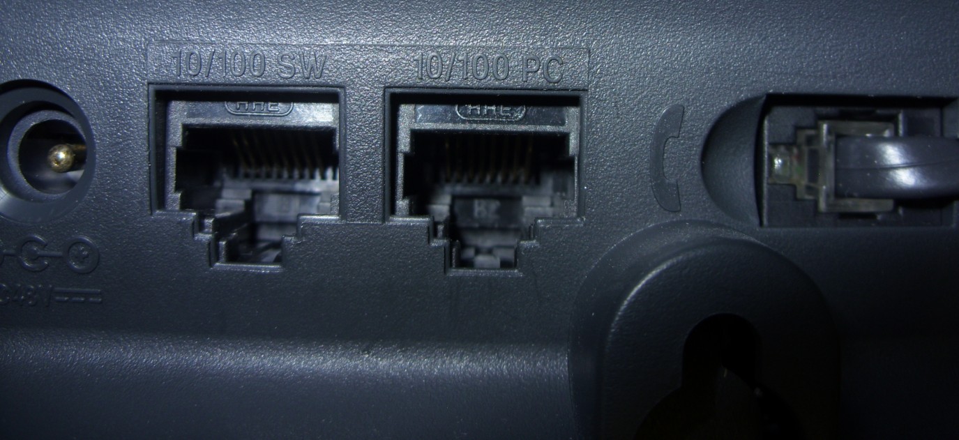
When implementing VLANs on your network, you use trunk ports for your inter-switch links, but for your client access ports, you use Access mode instead of Trunk mode. When you unbox your new switch, all ports are in Access mode by default; that means that they expect to have computing devices connected to them, and they will automatically insert IEEE 802.1Q tags into any Ethernet frames that do not already have tags. Typically, ports in Access mode expect to see untagged traffic because computers and other devices do not know how to pre-tag Ethernet frames. If you have implemented IP telephony, IP phones are capable of tagging their own traffic through an integrated two-port switch, as shown in Figure 5-3.
Figure 5-3: The two-port switch integrated into Cisco IP phones.
A switch does not expect to see traffic with VLAN tags on ports in Access mode because most devices on those ports do not tag their own traffic; traffic on Trunk mode ports automatically allow traffic tagged for any VLANs to be sent to connected switches. Because Trunk mode ports send traffic tagged for any VLAN, they expect to see traffic arriving from connected switches tagged for any VLAN.
Passing traffic from VLAN to VLAN
If you read about VLAN information in Book III, you likely expect all of this VLAN information to be Layer 2 or at the data link layer; it is. VLANs allow you to isolate users from each other by placing them in different VLANs, but now how do you pass traffic from one VLAN to another VLAN? Doing so involves the use of a Layer 3 device to route the traffic from one VLAN to another; yes, that would be router. Therefore, if your router does not support VLANs or VLAN tagging, this process will require an interface configured on each VLAN, which can be an expensive proposition. For example, in my case, I would have to purchase a router to support an interface for each VLAN running on my network. The better solution is to purchase a router that supports VLANs, which means you can connect a single interface on your router to a Trunk mode port on your switch, which allows the router to internally route between virtual VLAN interfaces. The other option you have available to you is to purchase a Layer 3 switch, which is a switch with routing functions built into it. That is, they are capable of providing all the inter-VLAN routing functionality, without leaving the switching device.
![]() A managed Layer 2 switch will see tagged or untagged data, and the switch may be configured to allow traffic on specified VLANs to be forwarded or blocked. If there is untagged traffic, this switch can place a VLAN tag into the existing header or encapsulate the frame if sending it over an ISL link. Finally, trunk ports will pass traffic for all VLANs by default, unless told otherwise.
A managed Layer 2 switch will see tagged or untagged data, and the switch may be configured to allow traffic on specified VLANs to be forwarded or blocked. If there is untagged traffic, this switch can place a VLAN tag into the existing header or encapsulate the frame if sending it over an ISL link. Finally, trunk ports will pass traffic for all VLANs by default, unless told otherwise.
Several default VLANs are created on your switch that cannot be removed. These include VLANs 1 and 1002–1005. The latter VLANs are used for Token Ring and FDDI networks; VLAN 1 is the default VLAN and is used for Ethernet.
![]() Although supporting 4096 Per VLAN Spanning Tree (PVST) would be nice, one for each VLAN, there is an IOS limit of 64 instances of spanning tree instances. So if you are using PVST, as you do in the next chapter, only the first 64 VLANs will have spanning tree enabled, and it will be disabled for the remaining VLANs.
Although supporting 4096 Per VLAN Spanning Tree (PVST) would be nice, one for each VLAN, there is an IOS limit of 64 instances of spanning tree instances. So if you are using PVST, as you do in the next chapter, only the first 64 VLANs will have spanning tree enabled, and it will be disabled for the remaining VLANs.
Setting up VLANs
To create a VLAN on your switch, you can type only one command in Global Configuration mode: set vlan VID, which puts the switch into VLAN Configuration mode. However, typically you type a second command, the name command, for clarity while in VLAN Configuration mode. That is all you need to do to create a new VLAN. The bigger part of the job includes ensuring that it is available on all the other switches and assigning ports on the switches to VLAN. The following code creates a test VLAN with an ID of 20:
Switch1>enable
Switch1#configure terminal
Switch1(config)#set vlan 20
Switch1(config-vlan)#name Test_VLAN
Switch1(config-vlan)#end
Now that you have created this VLAN, you can use it as a management interface for this switch. To use it as a management interface, you assign an IP address to the network interface, as opposed to the VLAN interface. You do so with the interface command, which you will use to configure a router interface with an IP address. (You can refer to Book III, Chapter 3, which includes how to set the default gateway.)
Switch1>enable
Switch1#configure terminal
Switch1(config)#interface vlan 20
Switch1(config-if)#description Test VLAN
Switch1(config-if)#ip address 192.168.20.1 255.255.255.0
Switch1(config-if)#end
Using a computer connected to a port on the switch and configured for the same VLAN, you can attempt to ping this address (192.168.20.1). You should find that you could not access the address because the VLAN interface is not enabled. Showing the running configuration sheds light on the issue. Here is the issue and the corrective action:
Switch1>enable
Switch1#show running-config interface vlan 6
Building configuration...
Current configuration : 113 bytes
!
interface Vlan20
description Test VLAN
ip address 192.168.20.1 255.255.255.0
no ip route-cache
shutdown
end
Switch1#configure terminal
Switch1(config)#int vlan 20
Switch1(config-if)#no shutdown
Switch1(config-if)#
1w4d: %LINK-3-UPDOWN: Interface Vlan20, changed state to up
1w4d: %LINK-5-CHANGED: Interface Vlan1, changed state to administratively down
1w4d: %LINEPROTO-5-UPDOWN: Line protocol on Interface Vlan20, changed state to up
1w4d: %LINEPROTO-5-UPDOWN: Line protocol on Interface Vlan1, changed state to down
This code brings up VLAN 20 as the management VLAN, but look what happened to VLAN 1, which was the previous management VLAN — it is now disabled. Unlike routing interfaces, which allow multiple interfaces to be up and running, in this case, you are looking at just the management VLAN, and there can only be one. So as you enable another VLAN as the management VLAN, the existing management interface and VLAN are disabled. If you really want to, or need to, use VLAN 1 for your management VLAN, you must issue the no shutdown command for interface vlan 1. I cover the shutdown and no shutdown commands in Chapter 3 of this minibook.
The last step in this exercise is to assign other ports to the VLAN. Here are two common ways:
• Dynamic Assignment with RADIUS Server: A complicated process of storing MAC addresses in a RADIUS server and passing VLAN assignments back to a switch with a computer attached.
• Port-based assignments: The most common method for VLAN assignments are port-based assignments. If you connect a device to a specific port on a switch, it will be associated with a specific VLAN. If you plug it into the incorrect port, it will be associated with an incorrect VLAN.
Configuring a range of interfaces
Configuring a range of interfaces or ports on your switch prevents you from having to configure each of these interfaces individually.
Putting your switch into Interface Range Configuration mode allows you to configure multiple ports at the same time, reducing your work when making major configuration changes on your switch. You denote a range for interfaces by specifying the starting interface and the last interface in the range. The following code example uses this technique to configure interfaces 8 through 12. Once the proper Configuration mode is specified, you use the switchport access command to place these ports in vlan 5. Trunk ports are ports used for inter-switch connections, while access ports are used to connect devices to your switch. The switchport command is used to change between Trunk mode and Access mode. The following example lists the other directives available to the switchport command:
Switch1>enable
Switch1#configure terminal
Switch1(config)#interface range fastEthernet 0/8 , fastEthernet 0/12
Switch1(config-if-range)#switchport ?
access Set access mode characteristics of the interface
host Set port host
mode Set trunking mode of the interface
nonegotiate Device will not engage in negotiation protocol on this
interface
port-security Security related command
priority Set appliance 802.1p priority
protected Configure an interface to be a protected port
trunk Set trunking characteristics of the interface
voice Voice appliance attributes
Switch1(config-if-range)#switchport access vlan 5
Switch1(config-if-range)#end
With ports 8 through 12 now associated with VLAN 5, you can verify this configuration using the trusty show command. In this case, the most appropriate command is show vlan brief, whose output appears in the next command example. Be sure to notice the difference in the VLAN names that appear in this listing. VLAN 2 is assigned a descriptive name; VLAN 15 is assigned a name that is not very descriptive; VLAN 10 is not assigned a name at all, making it even less descriptive. If you want to ensure the proper devices and ports are assigned to the proper VLANs, use descriptive names on your VLANs.
Switch1>enable
Switch1#show vlan brief
VLAN Name Status Ports
---- -------------------------------- --------- -------------------------------
1 default active Fa0/1, Fa0/2, Fa0/3, Fa0/4
Fa0/5, Fa0/6, Fa0/7
2 Executives active
5 VLAN0005 active Fa0/8, Fa0/9, Fa0/10, Fa0/11
Fa0/12
10 VLAN0010 active
15 VLAN_15 active
20 Test_VLAN active
1002 fddi-default act/unsup
1003 trcrf-default act/unsup
1004 fddinet-default act/unsup
1005 trbrf-default act/unsup
VLAN database
All of the VLAN information is stored in the VLAN database. This database is on your flash memory and is shown in this directory listing:
Switch1>enable
Switch1#dir flash:/vlan.dat
Directory of flash:/vlan.dat
3 -rwx 780 Mar 13 1993 22:52:09 +00:00 vlan.dat
7741440 bytes total (1058816 bytes free)
If you want to enter the VLAN database and make changes to that data directly, you can enter the Configuration mode by typing vlan database, but this is a depreciated method of making changes to the data, so you want to limit your changes to one of the standard modes.
Switch1>enable
Switch1#vlan database
% Warning: It is recommended to configure VLAN from config mode,
as VLAN database mode is being deprecated. Please consult user
documentation for configuring VTP/VLAN in config mode.
If you delete the VLAN database, you will remove all VLAN information on your switch. This is not recommended. If you remove all your VLANs, systems that were configured for specific VLANs will no longer be able to communicate properly.
Getting Started with VLAN Trunking Protocol (VTP)
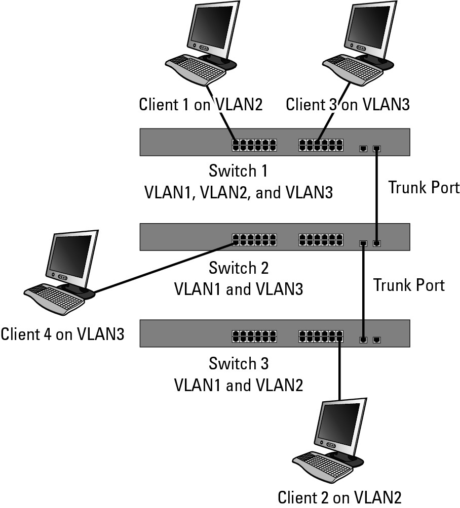
While working with VLANs, you have probably found that it is not difficult to add a VLAN to a switch. It is also not very difficult to configure trunk links between switches, which by default, carry all VLAN traffic; however, the problem you may run into is adding the VLANs to all of your switches. I have worked with switches from other manufacturers that do not include a facility like VTP. Ensuring that all VLANs are configured on all switches is important because if you are not careful with the configuration, you can find that systems on the same VLAN are not able to communicate with each other. Figure 5-4 illustrates how this problem can happen. Notice that Switch 1 and Switch 3 are configured for VLAN2 and both have users; but these devices cannot communicate with each other because Switch 2 is not configured to support VLAN2. Because Switch2 is not configured for VLAN2, it will not pass traffic for VLAN2. The users on Switch 1 and Switch 2 on VLAN3 are able to communicate with each other without an issue because there is a direct link on the correct VLAN between the systems.
Figure 5-4:
VLANs must be configured on all switches to support communication among devices.
VTP alleviates this issue by automatically replicating information about your VLANs from one switch to another so that all switches on your network are aware of all VLANs on your network.
Learning how VTP works
As I mentioned when discussing Figure 5-4, a lack of consistency in how you apply the VLAN configuration across your network can lead to communication errors or security issues on your network. One security issue that can arise is having two groups in different parts of the network using the same VLAN ID. Initially, this is not an issue, but if a link is established between the VLANs, users you want to keep separate will be combined. To resolve this issue, Cisco created a protocol to be used on their switching devices. Because switching operates at Layer 2, this new solution operates at Layer 2 as well.
By making use of trunk links between switches, Cisco added some new network frames to be sent over those links. These additional frames were designed to pass VLAN information over the trunk links — thereby being a VLAN Trunking Protocol. So the information that is sent over these links allows modification of VLAN information between switches on either side of the trunk link, including adding, removing, and renaming VLANs, assuming they all belong to a common VTP domain.
A VTP domain is a grouping mechanism used to amalgamate a group of switches into a single management unit. Depending on the roles assigned to each switch, you can create and manage the VLAN configuration on any switch, and those changes will be relayed to all other switches on your network. This also eliminates the chance of having duplicate names or VLAN IDs intended for different types of users or roles.
Without using VTP, I have had to document VLAN configurations for clients or deploy a new VLAN out to their corporate network consisting of numerous switches. Both of these jobs can be daunting. Similarly, when adding a new switch to a network, ensuring that it has your entire current network VLANs added to its configuration is very important. VTP makes this last task as easy as plug-and-play.
Implementing VTP
The first step in implementing VTP is to configure or create a VTP domain. All switches within the same VTP domain will share VLAN information. If you have groups of switches that you do not want to share information, just be sure to use two different VTP domains. Remember though, if you have a switch that has never been configured and you connect it via a trunk port, it will automatically take the VTP domain of the switch on the other end of the trunk port. In this case, you need to configure the VTP domain prior to configuring the trunk port.
The information shared through VTP includes the following:
• Management Domain
• Known VLANs and VLAN configuration
• VTP configuration revision number
Being leery of the VTP configuration revision number
The VTP revision number is important because it determines which updates are to be used. When you set a VTP Domain Name, the revision number is set to zero, after which each change to the VLAN database increases the revision number by one. When a switch receives VTP information from a neighboring switch, the first switch processes data only for the same domain when the revision number is higher than its own.
![]() Always check your VTP revision numbers before adding a switch to your network or when adding a switch back to your network. If you remove a switch and place it in your lab, you may create additional VLANs or delete all configured VLANs — either of which will increase the revision number. When you add that switch back into your production network, the switch will have the highest revision number of any device on the network. This forces the deletion of all existing VLANs to all other switches because they will have a lower revision number. Having all of your VLAN information deleted could be ruinous for your data network. Always use
Always check your VTP revision numbers before adding a switch to your network or when adding a switch back to your network. If you remove a switch and place it in your lab, you may create additional VLANs or delete all configured VLANs — either of which will increase the revision number. When you add that switch back into your production network, the switch will have the highest revision number of any device on the network. This forces the deletion of all existing VLANs to all other switches because they will have a lower revision number. Having all of your VLAN information deleted could be ruinous for your data network. Always use show vtp status to check revision numbers. You can reset your revision number on the switch you are adding to the network by changing the VTP domain to something else and then changing it back.
Pruning in the VTP tree
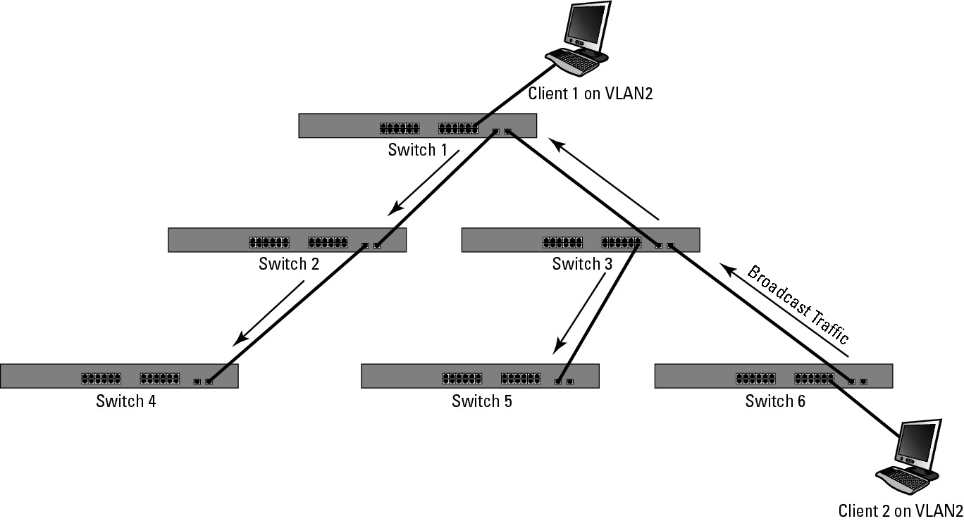
VTP solves one problem for you — and immediately creates a new one. Without VTP, you would need to manually create VLANs on all your switches or at least on switches that support devices or pass traffic for that VLAN. This allows traffic, especially broadcast traffic, for that VLAN to pass only through switches that are required in the communication process. The issue you encounter when using VTP is that the VLAN is propagated over trunk links to all of your network switches. The result is that broadcast traffic, as shown in Figure 5-5, will be sent to all switches on your network. This would not be a concern if you had network devices in that VLAN existing on all switches, but you do not; therefore, you have created extra network traffic for no reason. In this case, there is a VLAN2 user on only two switches, interconnected by a third; you need to have the VLAN visible only on switches 1, 3, and 6.
Figure 5-5: VTP allows all VLAN traffic to be dispersed to all switches.
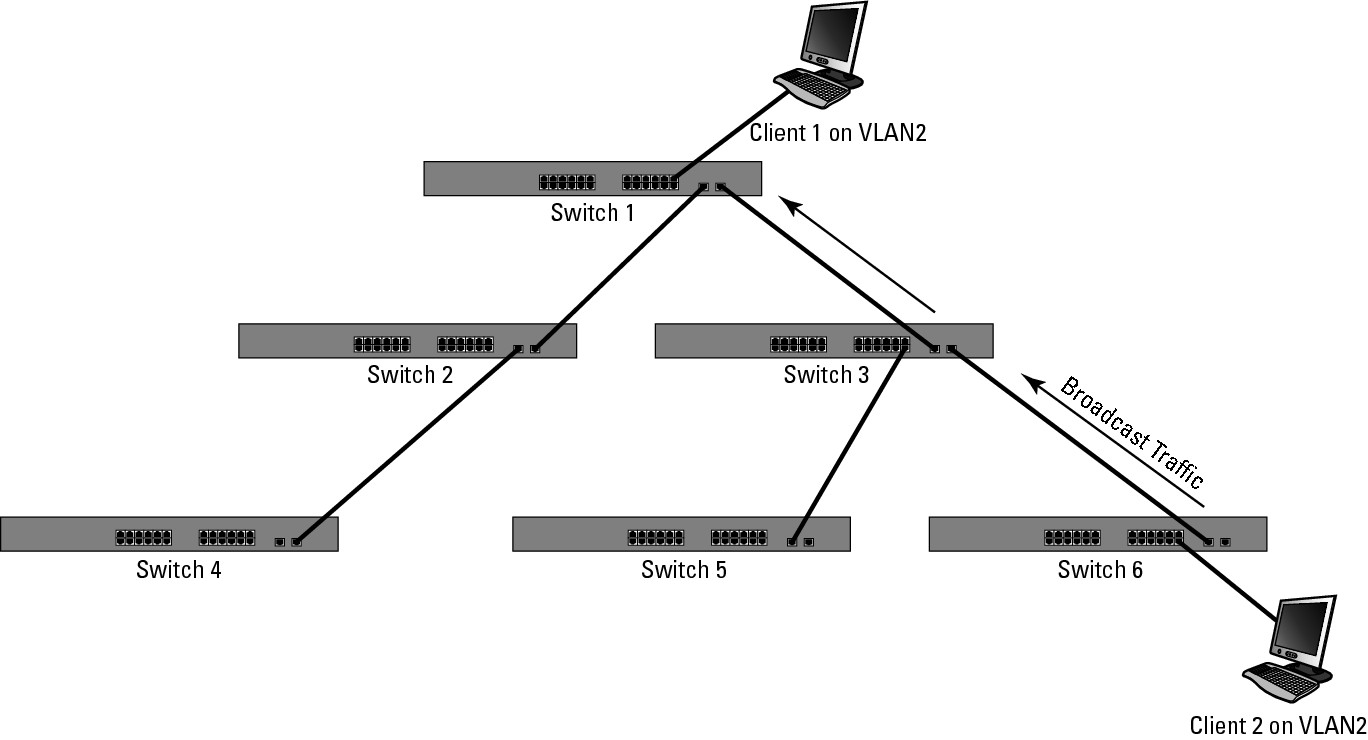
Enter VTP pruning, a solution that eliminates the need to manually maintain the VLAN information on switches. The pruning feature prevents VLAN data from traversing needless links by monitoring traffic. You enable VLAN pruning on your switch in Global Configuration mode. After you enable VTP pruning, VLAN traffic will be evaluated for a very short time. After VTP determines what switches require what VLAN traffic to send to the switches, it will filter the traffic. After the filtering process starts, much of the background traffic (such as broadcasts) on your network will be reduced, as shown in Figure 5-6. This filtering is not a permanent state because when ports on the other switches are put in the VLAN, the required VLANs for those switches will be unpruned.
Figure 5-6:
VTP Pruning automatically filters traffic to where it is needed.
![]() Only VLANs 2 to 1001 are pruned by default. VLAN1 is used for system tasks, such as carrying management data, so it will never be pruned. VTP pruning is not compatible with switches that are running in Transparent mode (because it is not able to manage them).
Only VLANs 2 to 1001 are pruned by default. VLAN1 is used for system tasks, such as carrying management data, so it will never be pruned. VTP pruning is not compatible with switches that are running in Transparent mode (because it is not able to manage them).
Configuring VTP
You must do a few things to configure VTP. You need to configure a port on your switch as a trunk (refer to Book III, Chapter 3, for the steps to complete this process); then you need to enable VTP. You use three operating modes with VTP that you designate in Global Configuration mode:
• VTP Client mode: When running in Client mode, your switch will only receive configurations from other devices and will not allow changes to VLANs to be made on that specific switch.
• VTP Server mode: This mode allows you to make changes and propagate those changes out to all other switches in the domain. This is the default mode on your switches when you unpack them. How many servers can you have on your network? Well, as many as you want. Your VTP server will send VTP advertisements through 802.1Q trunk links to other switches, keeping them aware of any changes that occur on the switch. VTP Server mode switches will also accept VTP advertisements from other switches and apply revisions that are more recent.
• VTP Transparent mode: When a switch is running in this mode, you can create and modify VLANs on that switch, but those changes are not sent to other switches on the network. You can pass VTP through the switch, but the switch will not participate with VTP; rather it will have its VLAN configuration set and stored locally.
The default settings for VTP are as follows:
• VTP Domain Name: Null
• VTP Mode: Server
• VTP Version 2 State: Disabled.
VTP version 2 supports Token Ring: This represents the only difference between version 1 and version 2. If you are not using Token Ring, then you should use version 1.
• VTP Password: None
• VTP Pruning: Disabled
The other commands you will want to use in Global Configuration mode are listed here. In order to configure VTP, you only need to specify a domain name and a password. The rest of the options do not need to be changed. These two commands will modify the default options.
Switch1(config)#vtp domain MyVtpDomain
Switch1(config)#vtp password MyVtpPassword
Now, walk through a brief configuration. Note that a switch currently does not have any special VLANs configured, as shown here:
Switch2>enable
Switch2#show vlan brief
VLAN Name Status Ports
---- -------------------------------- --------- -------------------------------
1 default active Fa0/2, Fa0/3, Fa0/4, Fa0/5
Fa0/6, Fa0/7, Fa0/8, Fa0/9
Fa0/10, Fa0/11, Fa0/12
1002 fddi-default act/unsup
1003 token-ring-default act/unsup
1004 fddinet-default act/unsup
1005 trnet-default act/unsup
Because you want the entire VLAN configuration copied to this switch, you will want to use VTP. However, you have determined that you will not need to be able to make changes to the overall network VLAN configuration from this switch, which is ideal for VTP Client mode. You also configure it for the network VTP domain that you are working with here, which includes a password. Notice the status messages you get as you make the configuration changes:
Switch2>enable
Switch2#configure terminal
Enter configuration commands, one per line. End with CNTL/Z.
Switch2(config)#vtp mode client
Setting device to VTP CLIENT mode.
Switch2(config)#vtp domain edtetz.net
Changing VTP domain name from NULL to edtetz.net
Switch2(config)#vtp password MyVtpPass
Setting device VLAN database password to MyVtpPass
Switch2(config)#end
Even though you made these changes, if you check the VLAN configuration on the switch, you will not see any changes. That is because VTP information passes only through trunk ports, which have not been configured on this switch. You have already made the necessary changes on your other network switches, like Switch 1, so you just need to make the change here. Now, make sure that all ports that interconnect switches are configured as trunks and are actually trunking:
Switch2>enable
Switch2#configure terminal
Enter configuration commands, one per line. End with CNTL/Z.
Switch2(config)#interface fastEthernet 0/1
Switch2(config-if)#switchport mode trunk
Switch2(config-if)#end
Wait just a few seconds, and the VTP traffic will start flowing through to this switch. Once that happens, you are able to check the status of the VLANs and see the change based on the VLAN data that comes through from Switch 1. Here is how show vlan brief looks now.
Switch2>enable
Switch2#show vlan brief
VLAN Name Status Ports
---- -------------------------------- --------- -------------------------------
1 default active Fa0/2, Fa0/3, Fa0/4, Fa0/5
Fa0/6, Fa0/7, Fa0/8, Fa0/9
Fa0/10, Fa0/11, Fa0/12
2 Executives active
5 VLAN0005 active
10 VLAN0010 active
15 VLAN_15 active
20 Test_VLAN active
1002 fddi-default act/unsup
1003 token-ring-default act/unsup
1004 fddinet-default act/unsup
1005 trnet-default act/unsup
Viewing your VTP settings
VTP changes the VLAN database of your switch; therefore, you will not see VTP information in your running configuration. This is sometimes confusing because whenever you make changes in Global Configuration mode, the changes show up in your running configuration — except your VTP settings. To see the VTP settings, use the show command. Passwords are listed with the password command.
Switch1>enable
Switch1#show vtp ?
counters VTP statistics
password VTP password
status VTP domain status
The most useful option probably is status, which shows you the VTP configuration — minus the password — for your switch. Note that you see the revision number here, as well as the mode and domain name:
Switch1>enable
Switch1#show vtp status
VTP Version : 2
Configuration Revision : 1
Maximum VLANs supported locally : 128
Number of existing VLANs : 11
VTP Operating Mode : Server
VTP Domain Name : edtetz.net
VTP Pruning Mode : Disabled
VTP V2 Mode : Disabled
VTP Traps Generation : Disabled
MD5 digest : 0xBC 0x8C 0xD6 0xE4 0x2F 0xA4 0x5D 0x28
Configuration last modified by 192.168.1.243 at 3-20-11 22:27:26
Local updater ID is 192.168.1.243 on interface Vl1 (lowest numbered VLAN interface found)
counters is a little less useful — unless you are not seeing any of the VLAN updates from neighboring switches. In that case, counters is very useful because it shows you the advertisements that you sent and received. If you are not receiving these, check the Trunk settings. The last thing you see in counters is the pruning information, which again will be useful if you have VTP pruning enabled because it shows where the pruning occurs on the network.
Switch1>enable
Switch1#configure terminal
Switch1#show vtp counters
VTP statistics:
Summary advertisements received : 6
Subset advertisements received : 1
Request advertisements received : 0
Summary advertisements transmitted : 7
Subset advertisements transmitted : 2
Request advertisements transmitted : 0
Number of config revision errors : 5
Number of config digest errors : 0
Number of V1 summary errors : 0
VTP pruning statistics:
Trunk Join Transmitted Join Received Summary advts received from
non-pruning-capable device
---------------- ---------------- ---------------- ---------------------------
Fa0/1 0 0 0