Chapter 10: Performing Intrusion Analysis
Within the cybersecurity industry, many organizations' systems and networks are being compromised by threat actors who will implant some type of malicious application that allows the victim's system to establish a connection back to a Command and Control (C2) server. Systems that are infected with malware should be isolated as soon as possible as the malware will attempt to spread across the network to infect other systems, and even attempt to connect to the C2 server for updates and instructions from the threat actor. These are just some examples of how threat actors and malware use your organization's network to do their bidding. As an up-and-coming cybersecurity professional, it's essential to understand the importance of performing intrusion analysis on a network and observe network traffic patterns for suspicious activities.
Throughout this chapter, you will learn about the types of data that are gathered by various source technologies and devices on a network, various firewall operations, techniques on capturing network traffic for analysis, the importance of detecting an intrusion as quickly as possible, and how to identify protocol headers in an intrusion.
In this chapter, we will cover the following topics:
- Identifying intrusion events based on source technologies
- Stateful and deep packet firewall operations
- Comparing inline traffic interrogation techniques
- Understanding impact and no impact on intrusion
- Protocol headers in intrusion analysis
- Packet analysis using a Packet Capture (PCAP) file and Wireshark
Technical requirements
To follow along with the exercises in this chapter, please ensure that you have downloaded the following:
- Wireshark: https://www.wireshark.org/
- 7-Zip: https://www.7-zip.org/
Link for Code in Action video: https://bit.ly/3nltjNE
Identifying intrusion events based on source technologies
As a cybersecurity professional, you will most likely be working within a type of security operation center (SOC), whether it's an in-house team or within a managed security service provider (MSSP). Regardless of the environment, you'll be exposed to many networking and security technologies and devices that are used to gather data about the network traffic. Such data is usually fed into Security Information and Event Management (SIEM) software and other threat management tools such as Security Orchestration, Automation, and Response (SOAR) tools.
The SIEM application is responsible for correlating all the events gathered from all networking and security devices within an organization and provides visibility of all potential security incidents that are occurring in real time. This allows security professionals to quickly see attacks as they are happening and gather details using a single pane of glass rather than manually checking the security logs on each individual device. The SIEM application assists with collecting and analyzing security events from various sources of alerts on the network. The SOAR platform has similar functionality to the SIEM application; however, it takes things a step further to provide automation or handling security incidents and investigations within a SOC.
Additionally, from time to time, you will be required to retrieve various security data to perform further analysis on a security incident on the network. It's important to understand which types of tools and security solutions are involved in providing certain types of data, simply because not all security devices or applications provide the same type of data for a security professional, and this can be a bit overwhelming when it's a time-sensitive situation to retrieve important data related to an event.
The following list outlines various sources of data during a network-based intrusion event:
- Intrusion detection system (IDS)
- Intrusion prevention system (IPS)
- Firewall
- Network application control
- Proxy logs
- Antivirus
- Transaction data (NetFlow)
Let's look at each of them in detail.
IDS/IPS
An IPS is a security appliance that is placed in line to inspect both inbound and outbound network traffic, while an IDS is not placed in line to block malicious traffic but is able to monitor for intrusions. An IDS/IPS inspects inbound traffic from the internet to ensure there are no malicious scripts or applications that are hidden within packets before they enter the enterprise network. If a packet contains malicious code, an IPS will block the traffic and send an alert. Many may not see the benefit of inspecting outbound traffic. Imagine if your corporate network contains an outbreak of a threat; if your security appliances can prevent this threat from leaving your network, you simply prevent other systems from being infected on the internet. However, on next-generation firewall (NGFW) appliances, the IPS is a built-in module within the firewall itself and simply requires a license to activate it.
The following diagram shows the placement of an IPS on a network:
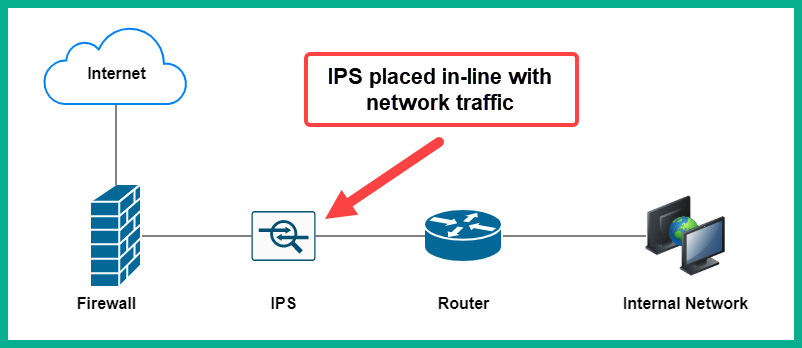
Figure 10.1 – IPS placement on a network
Therefore, as a security professional who wants to get a listing of the most frequent attacks that have occurred within your network, the IDS/IPS security appliance is able to provide such security logs for auditing. Additionally, the data obtained from the IDS/IPS will provide the origin of the attack, as well as the target or destination of the attack. To put it simply, an IDS can alarm, identify, and log an attack but not prevent it, while an IPS can block an attack and prevent it from entering the network.
Putting together all the data from the IDS/IPS, you will be able to determine any type of attack trend that may be occurring, such as whether a Denial of Service (DoS) attack is occasionally originating from a certain country or whether malware is connecting to a common C2 server somewhere on the internet.
Firewall
A firewall is able to filter either inbound or outbound network traffic by leveraging five tuples. These five tuples are simply five values that are used to identify a flow of traffic on a network, and are listed as follows:
- Source Internet Protocol (IP) address
- Destination IP address
- Source service port number
- Destination service port number
- Protocol
Therefore, all packets that contain the same source and destination IP address, source and destination service port number, protocol, and Class of Service (CoS) values are determined to be a flow of traffic between a source and destination host. Usually, the first five values are used to identify a single flow of traffic on a network.
The following screenshot shows a sample capture using Wireshark:
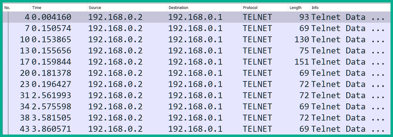
Figure 10.2 – Observing the five tuples
As shown in the preceding screenshot, we can identify a flow of traffic between a source IP address of 192.168.0.2 and a destination host with an address of 192.168.0.1. Additionally, the source port is 1550 and destination port is 23, and the protocol is the Transmission Control Protocol (TCP), as illustrated in the following screenshot:

Figure 10.3 – Packet details
The preceding screenshot shows the packet details, which contain the five tuples of the flow traffic between the source and destination. The firewall security appliance is able to permit or deny traffic flows between networks simply by leveraging the five tuples to identify the traffic flows. Furthermore, the firewall can filter incoming and outgoing traffic.
Network application control
Using network application control, a security solution such as Cisco Firepower Management Center (FMC) gathers intelligence regarding all the Cisco security solutions and appliances on a network to provide visibility for everything that is happening on the network. Imagine you're a security professional within your organization and you want to determine which are the most frequently used applications on the network, the most used network protocols, and users who generate the most traffic based on data types and even threats. Using a solution that provides a full view of application visibility and control on your network will help you gather these types of data.
A simple example of how gaining network application control can help a cybersecurity professional is to imagine that a few systems on your network have been infected with malware. The compromised systems have established a connection to the C2 server on the internet using the Internet Control Message Protocol (ICMP). For many people, if you see ICMP as the network application protocol, you may think someone is performing a network connectivity test using the Ping utility between two devices and that it's harmless. However, threat actors can use common network and application-layer protocols to conceal their malicious payload, simply to avoid detection and evade security systems. Therefore, as a cybersecurity professional, you will notice traffic patterns that are suspicious based on the source and destination of the network traffic.
The following screenshot shows the most common malware threats and connections on Cisco FMC:

Figure 10.4 – Malware threats and connections on Cisco FMC
As shown in the preceding screenshot, Cisco FMC provides network visibility on the most common malware threats that occur within an organization. Furthermore, we are able to determine the types of potential threats that use various connection types. These are just some of the many visibility features that Cisco FMC provides.
Tip
To learn more about Cisco FMC, take a look at the following link:
Knowing the type of data that is collected within a security appliance (such as by providing network application control) can help you quickly get visibility on applications that are running on your enterprise network and determine applications that are not permitted on your network as well.
Proxy logs
Proxy logs help a cybersecurity professional to determine whether users are attempting to visit prohibited websites. A proxy server sits between the users on a corporate network and the internet. Rather than each user device sending its web requests directly to the destination, the web request messages are sent to a proxy server. The proxy server inspects the messages and determines whether they are permitted or denied. If the traffic is permitted, the proxy server forwards the request to the destination web server on behalf of the original sender. When the proxy server retrieves the content, it is cached and a copy is sent to the internal user on the network.
Many organizations use proxy servers to filter traffic based on the user, application, and services that are being requested. Additionally, with each request or transaction that is carried out, a log message is generated by the proxy server as a record of the event.
The following diagram shows a simple deployment of a proxy server on an internal network:
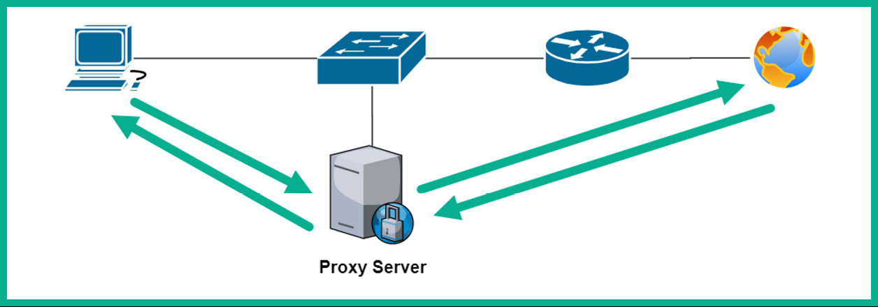
Figure 10.5 – Proxy server deployment on a network
The proxy logs will usually contain details about transactions, such as the user who made the request, the application that was used, the types of services, data about the five tuples, and the date and timestamps of the events. This information can be very useful for determining how a user was able to download a malicious file from the internet, or even access an infected website.
Antivirus
Regardless of whether the client system has an antivirus or anti-malware protection solution, these host-based security solutions are able to provide log messages based on the detection of a threat and can generate event alerts if something suspicious happens on the system (and if a threat is blocked as well).
The following screenshot shows an example of the protection history of Windows Security on a client:

Figure 10.6 – Protection history
As shown in the preceding screenshot, this is the Window Security center on a Windows 10 computer. The protection history provides a simple history of threats that were blocked recently on the client's computer. As shown, the AcroRd32.exe application attempted to access %userprofile%Documents, which happens to be a location protected by Windows Security. As a cybersecurity professional, it's important to use the details found within these types of log messages and history data to determine whether an application or file was truly malicious and how the actions performed by the antivirus or anti-malware solution prevent an outbreak.
Since the event was captured using Windows Security on a Windows 10 system, we can drill down even further to view the actual logs for Windows Defender by opening the Event Viewer application on Windows 10 and navigating to Applications and Services Logs | Microsoft | Windows | Windows Defender | Operational.
The following screenshot shows the actual log file that is related to the previous event:

Figure 10.7 – Windows Defender log
As shown in the previous screenshot, since Windows Defender is built into the Windows 10 operating system, all logs for the security application are found within the Windows Event Viewer application. As shown, we are able to get in-depth details about the actions performed by Windows Defender and related details such as the user, date and timestamps, processes, and so on.
Similar to installing a third-party antivirus or anti-malware solution, there will be logs that are generated for every event that has occurred on the application. Using this data with the antivirus logs helps a security professional to determine what really happened on the system and whether the threat was contained or not.
Elements of NetFlow and transactional data
In Chapter 4, Understanding Security Principles, we discussed the benefits of using NetFlow. To recap, NetFlow is a Cisco proprietary tool that is used for analyzing network traffic for reporting and monitoring purposes. It can monitor the flow of IP-based traffic between network devices such as switches, routers, and even firewalls. NetFlow is also used in the billing and accounting of network traffic to determine how much bandwidth was used by a user and applications on a network.
NetFlow is able to monitor and detect any anomalies on a network by observing the five tuples, listed here:
- Source IP address
- Destination IP address
- Source service port number
- Destination service port number
- Protocol
This is unlike a full packet capture, which provides you with all the data but can be overwhelming to analyze. Using NetFlow, you filter the traffic using the five tuples, which makes it easier for you to analyze large amounts of network traffic.
To put it simply, NetFlow provides transactional data from gathering statistics about all the flows it is monitoring between a source and a destination. This allows you to gather and store network data about your end devices, network applications and protocols, and users on the network. Therefore, you will be able to identify any malicious threats, attacks, and suspicious users on the network.
The following are some key elements that NetFlow helps us to resolve:
- It can detect whether data is being exfiltrated by a threat actor.
- It can detect whether a network scan is occurring.
- It can detect a DoS attack.
- It can detect whether there are misconfigurations on networking devices.
- It can detect whether systems are sending multicast or broadcast traffic.
NetFlow allows both a network and a security professional to gather transactional data about the traffic and data types on an enterprise network. NetFlow allows the security professional to determine whether any restricted network applications and protocols are being used. While you are not able to get details, as you would with a full packet capture, the transactional data provides really good visibility into the most used protocols and services on the network. Therefore, it's easy to detect whether malware is sending data back to a C2 server.
Additionally, transactional data helps a security professional to determine the traffic flows within an organization, such as between a source and a destination. It allows you to discover whether your security appliances, such as your firewall, are filtering traffic as they are configured too. If the firewall is permitting unwanted traffic, then the security professional can simply fine-tune the rules on the firewall.
Having completed this section, you have gained knowledge about how to identify intrusion events from various source technologies. Furthermore, you have learned about the benefits of using NetFlow to help you easily analyze large amounts of network traffic to detect cyber threats and anomalies on a network. In the next section, you will discover the characteristics of packet-filtering and stateful firewalls.
Stateful and deep packet firewall operations
Throughout the course of this book thus far, NGFW has been mentioned many times; however, the NGFW security appliance is usually deployed within very large enterprise networks that contain hundreds to thousands of clients and devices. However, within a smaller organization, you will commonly find a small-to-medium-sized network and, as expected, a small budget allocated for IT resources. This leads to less costly firewall solutions to safeguard the small business network from potential threats.
As a soon-to-be cybersecurity professional, it's important to be aware that there are other types of firewalls within the industry. Two common types of firewalls are outlined here:
- Deep Packet Inspection (DPI) firewall
- Stateful firewall
This leads on to say that not all types of firewalls operate the same. To put it simply, the DPI firewall and stateful firewall do not share equal capabilities with each other, and the same can be said of an NGFW as compared to either a DPI or a stateful firewall.
DPI firewall
A DPI firewall is able to inspect traffic at all layers of the Open System Interconnection (OSI) reference model and the TCP/IP protocol suite. You are probably thinking: Don't all firewalls have these capabilities? To put it simply, not all firewall security appliances are able to inspect traffic at all layers of the TCP/IP protocol suite. A DPI firewall is able to inspect the header of network packets to determine the source and destination details as with all types of firewalls, but it goes a step further to inspect the application layer.
Important note
The header within a packet contains source and destination addressing details such as Media Access Control (MAC) addresses, IP addresses, and service port numbers.
If a firewall is unable to inspect beyond the transport layer (layer 4), the firewall appliance will not be able to determine various traffic types. For example, since more internet servers use Hypertext Transfer Protocol Secure (HTTPS), a traditional firewall will not be able to identify traffic that is going to YouTube versus traffic that is going to a social media platform such as Facebook. Both the YouTube and Facebook servers use HTTPS to ensure encryption is provided between the client's web browser and the server, which creates a challenge in identifying the actual traffic type between destinations. The application-layer firewall can go further to inspect the application layer to determine whether the traffic is going to YouTube or Facebook, even if it's using HTTPS.
At the application layer, threat actors are able to encapsulate (hide) their malicious payload as common network protocol traffic. Therefore, an unaware network professional may see a lot of HTTP messages that are originating from an internal client machine on the corporate network with a destination to a public server on the internet. The HTTP packets can contain non-HTTP data at the application layer. Imagine placing a hidden message (malicious payload) into a red box. The objective is that you don't want anyone to see the red box or read its contents. Therefore, you place the red box into a regular green box (HTTP protocol) with a label to be delivered to a user. Everyone will see only the outer box (green) and no-one will detect the hidden contents of the red box.
The following diagram shows a visual representation of malware hidden within an HTTPS packet:
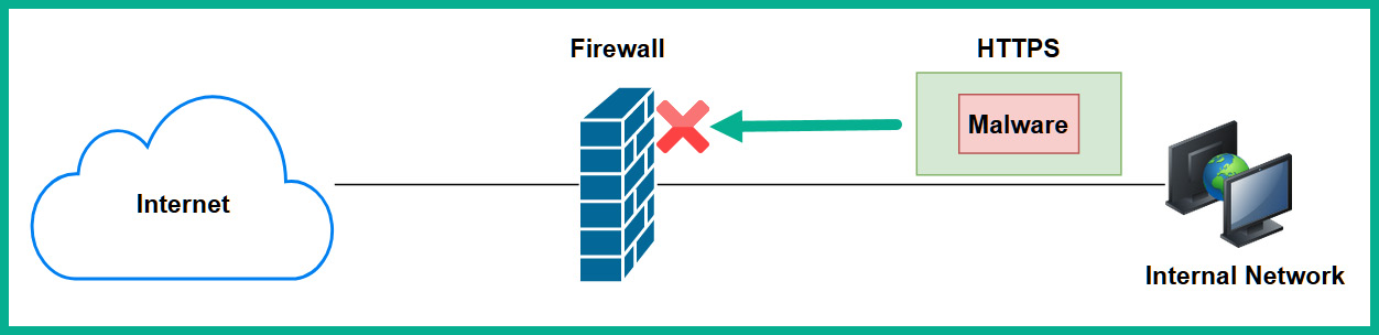
Figure 10.8 – Hidden malware within an HTTPS packet
Hence, DPI firewalls have the capability to inspect data at all layers of the TCP/IP protocol suite, especially at the application layer, to detect any suspicious data or malicious payloads. DPI firewalls can catch malware that is hidden within common network protocols, and even those that are hidden using HTTPS.
Stateful firewall
Another type of firewall is known as a stateful firewall, which has the capability to monitor traffic flows between networks. One key point to remember is that stateful firewalls always block all inbound traffic by default. Inbound traffic is any traffic that is originating from the internet to your internal corporate network.
The following diagram shows a stateful firewall blocking all inbound traffic:

Figure 10.9 – Stateful firewall blocking inbound traffic
This firewall maintains a state of connections that are originating from the inside zone (internal) to the outside zone (the internet). A firewall uses the concept of security zones to determine how to filter traffic using default configurations. The three different security zones on a firewall are listed here:
- Inside zone: The inside zone is the most trusted zone. This zone is assigned to your internal network and uses a security level of 100 on a Cisco firewall. Level 100 simply means the zone is fully trusted, therefore the firewall will trust all traffic originating from the inside zone by default and will allow the traffic to go to any other zone.
- Outside zone: The outside zone has a security level of 0. This a no-trust zone and it is usually assigned to a foreign network that does not belong to your organization, such as the internet. Traffic originating from an outside zone is not trusted and is blocked by default.
- Demilitarized Zone (DMZ): The DMZ is a semi-trusted zone that usually contains publicly accessible servers with very strict rules to permit specific traffic types. Organizations with servers that require access from regions of the internet are placed within the DMZ. If publicly accessible servers are placed within the corporate internal network, allowing users access to your internal network is not a good idea from a security perspective. Therefore, the DMZ is used for this purpose. The DMZ usually has a security level that is between 0 and 100. In a Cisco environment, a security level of 50 is commonly assigned.
The following diagram shows a visual representation of the security zones on a firewall:

Figure 10.10 – Security zones on a firewall
Important note
Traffic originating from the inside zone is allowed access to both the outside zone and the DMZ. However, traffic originating from the outside zone and the DMZ is not allowed access to the inside zone. Specific traffic is allowed from the outside zone to the DMZ only if permitted with rules on the firewall.
Let's imagine there's a client machine on the inside zone that wants to access a public web server on the internet. The stateful firewall will allow the traffic from the inside zone to the outside zone and keep track of the state of the outbound connection.
The following diagram shows the client attempting to establish a connection to a public server:

Figure 10.11 – Outbound connection
As shown in the preceding diagram, the client is attempting to send messages to Server A. The firewall inspects the header of the messages for the source and the destination addressing details. Since the connection is originating from a zone with a higher security level and going to a zone with a lower security level, the connection is allowed by default.
The following diagram shows an example of returning traffic from Server A:

Figure 10.12 – Returning traffic
As shown in the preceding diagram, Server A is sending returning traffic back to the client on the corporate network. Since the firewall is monitoring the state of the initial connection, the traffic is allowed to pass. However, notice that Server B is attempting to send traffic to the corporate network, and it's blocked by the firewall simply because the firewall does not have a state for this new connection from the inside zone.
Packet filtering
There are packet-filtering firewalls that only inspect the header of each packet. If you recall, the header within a packet contains the source and destination IP addresses and service port numbers. This type of firewall strictly depends on access control lists (ACLs) to permit or deny traffic. An ACL is a rule created by a network or security professional on a router or firewall to filter traffic between a source and a destination.
Important note
Since a packet-filtering firewall does not monitor the state of connections between a source and a destination, this type of firewall is also known as a stateless firewall.
This type of firewall operates between the network (layer 3) and transport (layer 4) layers of the TCP/IP protocol suite. Keep in mind that this type of firewall does not have the capability to inspect data at the application layer on a packet. If malware is hidden within a common network protocol such as HTTP, a packet-filtering firewall will not be able to block it.
Having completed this section, you have gained the skills to describe and identify various types of firewalls and their operations. In the next section, we will be taking a dive into comparing inline traffic interrogation techniques.
Comparing inline traffic interrogation techniques
As you will have realized, the Cisco Certified CyberOps Associate (200-201) certification is entirely based on detecting, analyzing, and preventing threats within an enterprise network. Additionally, throughout the course of this book, you have gained knowledge and skills on various types of security solutions and how to perform various tasks as a cybersecurity professional. However, regardless of whether you are working in a SOC or are part of the Information Technology (IT) team within an organization, you definitely need to monitor network traffic in real time to detect any potential threats that may be moving across the network.
While there are security appliances such as an NGFW and next-generation IPS on your network, sometimes these devices may miss a new emerging threat that hasn't been seen before in the wild (the internet). Implementing inline traffic interrogation techniques will allow you, as a cybersecurity professional, to capture network packets in real time as devices are sending and receiving messages.
The following are two common inline traffic interrogation techniques:
- Physical taps
- Switch Port Analyzer (SPAN)
Using an inline tap requires the cybersecurity professional to install a physical network inline tap between two devices. The tap can be installed anywhere on the network that you want to capture network packets. However, since the intention of capturing network traffic is to monitor for any suspicious traffic, always consider a location that is central to all devices.
The following diagram shows an example of how a physical inline tap can be implemented on a network:

Figure 10.13 – Implementing a physical tap
As shown in the preceding diagram, you can see a copy of the traffic between the switch and router, and a copy is being sent to a dedicated security monitoring device, which is running a network protocol analyzer.
The following are some key benefits of using a physical inline tap:
- It will create a full copy of the network traffic and send it to the security monitoring device.
- It does not drop any traffic.
- A physical inline tap does not require any sort of configuration.
- It is simple to implement on a network.
- Most inline taps do not require power for the device to operate.
- It does not create any contention on the network.
Keep in mind that an inline physical tap does not store the packets on the device itself, but rather forwards a copy to the network security monitoring device, which will store and analyze the packets.
Another technique both networking and security professionals use to capture network traffic is to configure a feature known as SPAN on Cisco switches. Using this feature eliminates the need for a physical inline tap on the network. Technically, SPAN allows you to create mirror interfaces (ports) on a switch to function as a physical inline tap.
The following code snippet shows configurations that allow a Cisco switch to monitor both interfaces, FastEthernet 0/1 and FastEthernet 0/2, and send a copy of the traffic out of FastEthernet 0/3:
Switch(config)# no monitor session 1
Switch(config)# monitor session 1 source interface FastEthernet 0/1
Switch(config)# monitor session 1 source interface FastEthernet 0/2
Switch(config)# monitor session 1 destination interface FastEthernet 0/3
The following diagram shows a visual representation of these configurations using SPAN:
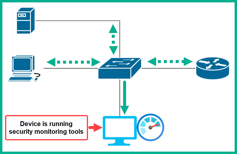
Figure 10.14 – SPAN on a Cisco environment
As shown in the preceding diagram, the switch is creating a copy of the network traffic that is passing between the switch and the router and sending the copy to the network security monitoring device for packet analysis.
The following are some key points every cybersecurity professional needs to know when using SPAN:
- SPAN is a feature that is built into the switch.
- Since the switch has to create a copy of the traffic, the layer 1 and layer 2 pieces of data are dropped from each packet before it is sent out to the network security monitoring device.
- Configuration is required on the switch to create the mirror interfaces.
- Since the switch has to create a copy of the traffic, there can be contention on the link.
- Remote SPAN (RSPAN) allows a security engineer to capture traffic between switches on the network that share a virtual local area network (VLAN).
Important note
To learn more about SPAN and RSPAN on Cisco devices, please see the following link:
Since using both an inline physical tap and SPAN generates a lot of data, it becomes challenging to go through all the packets to find a potential threat. Next, we will take a dive into understanding how NetFlow can be used to help us identify malicious activities.
Understanding impact and no impact on intrusion
Each day, new cyber threats are making their way onto the internet, and organizations are experiencing many challenges in detecting such attacks. One of the key objectives of a SOC is to detect a potential threat and cyber-attack as it happens on a network in real time. This allows security engineers to respond quickly, to prevent a huge outbreak from occurring. However, one of the main issues many security professionals face is the time it takes to detect a threat or a compromised system on their network.
Having the right security solutions—such as a firewall, IDS/IPS, Email Security Appliance (ESA), Web Security Appliance (WSA), Network Access Control (NAC), and so on—does not always ensure a perfectly secured environment. Imagine an organization invests in all the security solutions to fight against cyber-attacks but the security appliances and applications are not properly configured or fine-tuned. This can lead to various attacks and threats being undetected. Not being able to detect an attack or malware is a very bad thing for any organization.
There are many organizations that will not be aware that their network has been compromised by a threat actor. Some organizations take weeks to detect that their systems and network have been compromised, while some take months. One of the main objectives within security operations is to reduce the time it takes to detect an intrusion on a system and a network. According to Cisco Talos Intelligence Group, Cisco Advanced Malware Protection (AMP) provides an average time of 3.5 hours to detect a threat.
Reducing the time of detection is always a continuous process, whereby a security engineer has to tweak the settings and configurations of various security solutions. For a really good example to further understand the impact of detecting or not detecting an intrusion, let's take a look at the types of alerts provided by an IDS and IPS security appliance. As mentioned in Chapter 2, Exploring Network Components and Security Systems, an IPS is a proactive security appliance that sits in line with monitoring inbound and outbound network traffic. If the IPS detects malicious traffic, it will block the threat and send an alert to notify the security engineer.
The following diagram shows the typical deployment of an IPS on a network:
Figure 10.15 – IPS deployment
As shown in the preceding diagram, the IPS is placed behind the firewall. However, on an NGFW, the IPS module is usually integrated into the firewall and requires a software license for activation and to receive updates from the global threat intelligence team from the device's manufacturer.
Additionally, an IDS is a reactive security appliance, rather similar to an IPS. An IDS does not sit in line with the network, but is simply connected to a network switch and analyzes network packets. The following diagram shows a typical IDS deployment on a network:

Figure 10.16 – IDS deployment
As shown in the preceding diagram, the switch is configured with the SPAN feature, which enables the switch to send a copy of all traffic to a designated port. In this situation, the IDS is connected to the designated port. Since the IDS is not in line, it can only detect and alert if a threat is found.
Whether you are using an IPS or an IDS, these security solutions provide the following alert types:
- False positive: A false-positive alert occurs when the security solution, such as an IDS/IPS, sends an alert but an actual threat does not exist on the system or network. Imagine a user downloads a file from a trusted website, then performs a malware scan on the file. After the scan is completed, the results show the file is malicious.
As a typical user you will not trust the file, simply because the security solution says it's malicious. However, what if you decide to get a second opinion by performing a scan using a few other anti-malware programs and their results show the file is clean? Then, this is a case of the first anti-malware program providing a false-positive alert on the file. As a security professional, it's important to always pay close attention to alerts generated by your security solutions and fine-tune those appliances if needed to reduce the number of false-positive alerts being created. The fewer false-positive alerts, the less time is wasted by security analysts and engineers, therefore they can allocate their time to real threats.
- False negative: This alert type indicates that a threat exists on the system but no alarm is triggered. Implementing a security solution does not mean it will detect and stop every threat that exists, or all newly created threats. Sometimes, a security solution such as an IDS/IPS can miss threats, which can lead to your systems and network being compromised.
Security engineers are always analyzing network traffic and hunting for threats to fine-tune their security appliances and solutions, to catch any potential threats that exist. This is a continuous process of fine-tuning to ensure the IDS/IPS security appliances do not miss anything. It's important to reduce the number of false negatives, simply because threats can go undetected on your systems and network.
- True positive: This type of alert is simply defined as an alarm that is triggered because a threat exists. This is a type of alert security engineers fine-tune their security appliances and solutions to generate. When this alert is generated, security analysts and engineers know a real threat exists and they initiate their incident response (IR) actions immediately to determine whether the threat was contained or not.
- True negative: This type of alert simply means the security solution such as an IDS/IPS does not trigger an alarm because there are no threats on the system or network. This means the security solution is working as expected.
- Benign: In the field of cybersecurity, the term benign is used to describe something that poses no potential threat or harm to a system or network. Imagine you used various anti-malware programs to perform a scan on a file and the results indicate no threat exists. Then, we can simply say that the file is benign to the anti-malware programs.
The following screenshot shows an example of scan results on VirusTotal:
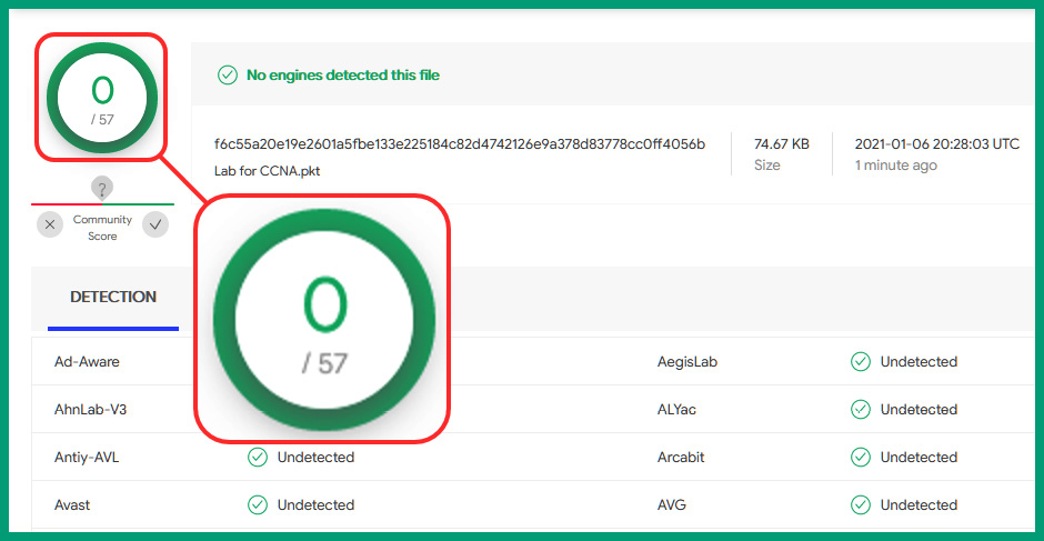
Figure 10.17 – Benign result
As shown in the preceding screenshot, the file is benign to all 57 anti-malware engines.
As a good practice, it's always recommended to ensure that your security appliances and solutions always have the latest version of updates installed to catch any new and emerging threats. Having completed this section, you have learned about the impact of detecting and not detecting an intrusion on an enterprise network. In the next section, you will learn about various network protocol headers in intrusion analysis.
Protocol headers in intrusion analysis
One of the fundamental skills each cybersecurity professional needs to have is a foundation in networking. This section is not designed to be a full-fledged networking topic but rather to provide you with the essential skills needed to identify the components within various protocol headers.
Tip
If you are interested in building a solid foundation in networking, consider getting a copy of Implementing and Administering Cisco Solutions: 200-301 CCNA Exam Guide, published by Packt Publishing:
As you have read throughout this book, and even from experience, devices always transmit messages when they are connected to a network. Using a packet analysis tool such as Wireshark, you can analyze each field within the headers of each packet.
Ethernet frame
An Ethernet frame contains the source and destination MAC addresses. The MAC address is considered to be a burned-in address (BIA), as the manufacturer of a device's network interface card (NIC) hardcodes the MAC into the physical NIC itself.
The following screenshot shows the Ethernet header of a frame using Wireshark:

Figure 10.18 – Ethernet header
As shown in the preceding screenshot, Wireshark shows us the sender's MAC address as 00:04:e2:22:5a:03 and the destination MAC address as 00:c0:df:20:6c:df. Additionally, Wireshark has the capability to resolve the first 24 bits of a MAC address to the device's manufacturer.
Important note
The source and destination MAC addresses change as the frame passes between layer 3 devices such as routers.
This information is useful to help you quickly identify the manufacturer for components on your network. As a cybersecurity professional, if an attacker is spoofing their MAC address or even launching an attack on your network, you can use the MAC address to trace the source device on a layer 2 network.
IPv4 and IPv6
An IP version 4 (IPv4) header contains a lot of data that helps the protocol deliver messages between a source and a destination. A threat actor can attempt to spoof the source IP address to avoid detection during their cyber-attack. As a cybersecurity professional, if you detect an unauthorized IP address on your network, this should be a red flag for immediate investigation and containment of the rogue system.
The following screenshot shows the IPv4 field header of a packet in Wireshark:
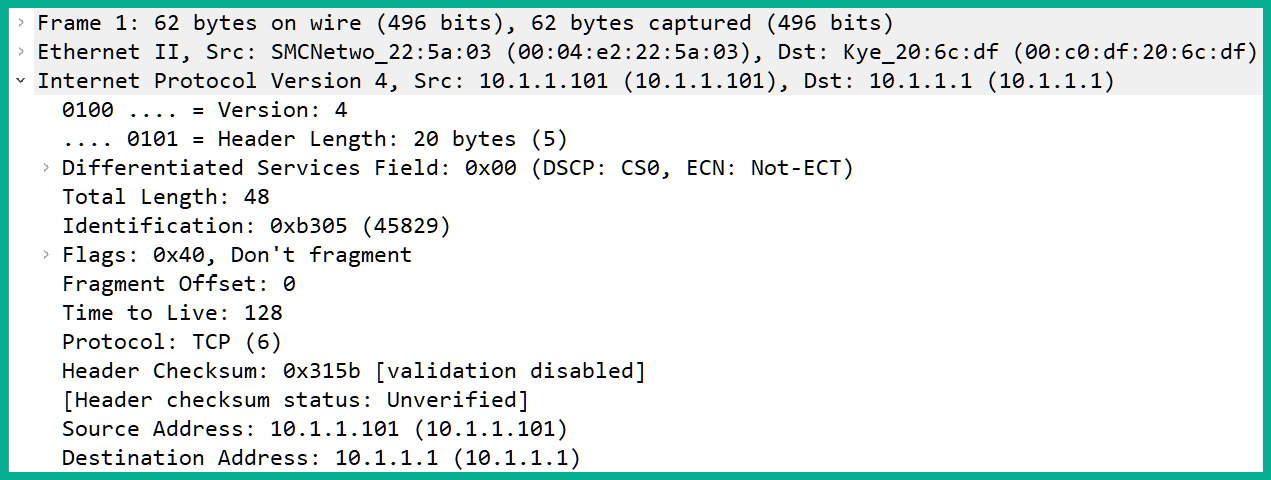
Figure 10.19 – IPv4 header
As shown in the preceding screenshot, Wireshark helps to identify the data found within each field of the IP header of the packet, such as the version, the length, the Time to Live (TTL), the protocol associated with the IP, and the source and destination IP addresses.
Additionally, Wireshark is able to provide details of IPv6 protocol headers, as shown in the following screenshot:

Figure 10.20 – IPv6 protocol header
As shown in the preceding screenshot, you are able to use Wireshark to obtain the source and destination IPv6 addresses and additional data within a packet. As you can see, there are fewer fields within an IPv6 header as compared to an IPv4 header.
TCP
TCP is a connection-oriented protocol within the transport layer of the TCP/IP protocol suite. The transport layer is responsible for the delivery of messages between a source and a destination and for assigning corresponding service port numbers to the segments.
The following screenshot shows the TCP header found within a message using Wireshark:

Figure 10.21 – TCP protocol header
As shown in the preceding screenshot, the TCP header contains the source and destination TCP service port numbers. These service port numbers are associated with application-layer protocols. Furthermore, you are able to identify the sequence number, acknowledgment number, window size, and flags that are configured on the message.
We can see that the message has a destination port of 80, which is associated with HTTP at the application layer of the destination host. This means that there is a web server running on the destination device. Additionally, you can see the source (sender's) service port number. As a cybersecurity protocol, you need to be aware that various malware—such as bots—use specific port numbers when communicating with their C2 servers. If you detect abnormal traffic that is either originating from or has a destination to a service port that is known for C2 traffic, you need to terminate the connection and investigate whether other systems within your network are attempting to establish similar outbound connections.
UDP
The User Datagram Protocol (UDP) is a connectionless protocol that operates at the transport layer of the TCP/IP protocol suite. Similar to TCP, UDP also assigns source and destination service ports to outbound messages from a host device.
The following screenshot shows the fields found within UDP using Wireshark:

Figure 10.22 – UDP header
As shown in the preceding screenshot, the UDP header contains fewer fields as compared to TCP, hence it is lightweight and faster in terms of transmitting messages on a network. As a cybersecurity professional, we need to observe traffic that originates from various source ports and the traffic that are going to host devices of a specific destination port.
ICMP
ICMP is a protocol used by many network professionals to test and troubleshoot end-to-end connectivity by using tools such as Ping and Traceroute. A threat actor can leverage the ICMP network protocol for a variety of cyber-attacks, such as exfiltrating data or even attempting to create a DoS attack.
The following screenshot shows a single host generating many ICMP request messages:

Figure 10.23 – ICMP flooding
As shown in the preceding screenshot, a source device of 192.168.43.9 is flooding both 8.8.8.8 and 8.8.4.4 with ICMP request messages. For each ICMP request message received by a host, the device has to process it and respond with an ICMP reply message back to the sender. The processing of each message takes up some of the computing resources available on the receiving devices, and if a sender is flooding hundreds or thousands of request messages to a specific destination, this will eventually create a DoS attack.
The following screenshot shows the fields found within the ICMP header using Wireshark:
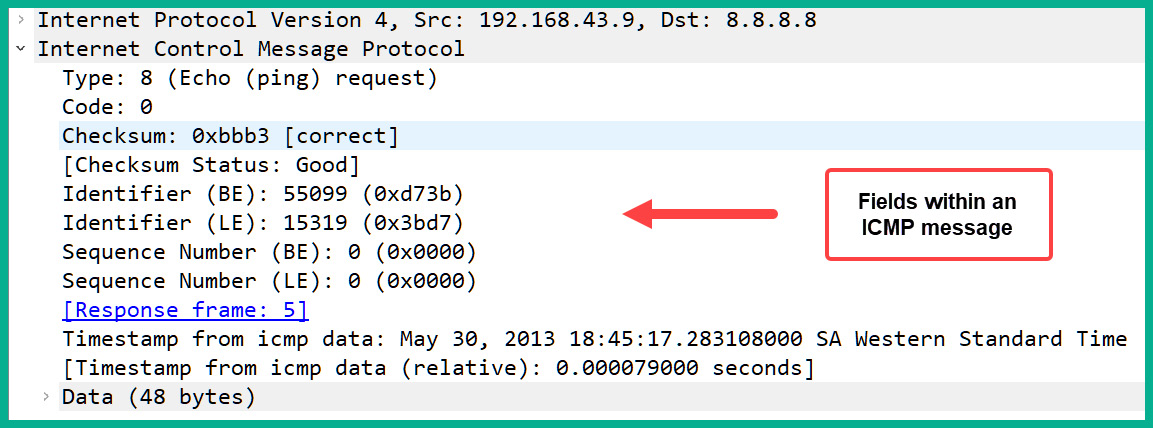
Figure 10.24 – ICMP header
As shown in the preceding screenshot, the ICMP header contains the ICMP type, code, checksum status, timestamps, and additional data. As a cybersecurity professional, if you observe a lot of suspicious ICMP activity occurring between a source and a destination on your network, it is worth investigating for a possible cyber-attack.
DNS
The Domain Name System (DNS) protocol is another common application-layer protocol. DNS is used to resolve the hostname to an IP address, which allows us to just remember the hostname of a device rather than the IP address of the system. DNS messages are frequently sent between a client and a DNS server. However, threat actors and malware can use the DNS protocol to both exfiltrate data from your organization and even establish a session between a compromised machine on your local network and a C2 server on the internet.
The following screenshot shows the fields of a DNS query message on Wireshark:

Figure 10.25 – DNS query header
As shown in the preceding screenshot, you can expand the fields within the header of a DNS message and view the data that is being exchanged between the client and the DNS server. Furthermore, you can see the actual queries and the responses that are being made. If you notice suspicious DNS queries are being sent to unknown or untrusted DNS servers, it may be a possible cyber-attack that should be investigated.
SMTP
The Simple Mail Transfer Protocol (SMTP) is an application-layer protocol that is used for sending emails on a network. This protocol is unsecure and sends data in plaintext, which allows an attacker to capture any sensitive and confidential information.
The following screenshot shows an email client exchanging messages with an email server:

Figure 10.26 – SMTP protocol
As shown in the preceding screenshot, we can see each SMTP packet being sent between a client (10.10.1.4) and the email server (74.53.140.153). In the Info column, you can see a summary of the plaintext messages that are being sent back and forth. You can even see the username (packet #12) and password (packet #14) that were used during the user authentication process.
Important note
Both Post Office Protocol 3 (POP3) and Internet Message Access Protocol 4 (IMAP4) are email protocols that are used to retrieve email messages from an email server. Similar to SMTP, both POP3 and IMAP4 are unsecure protocols that send data in plaintext.
With Wireshark, we can follow an entire stream of packets. This feature allows Wireshark to take all the packets that belong to a stream between a source and a destination and present them for use in a way that is simple to read and understand.
The following screenshot shows the TCP stream for the SMTP traffic between the client and the server:
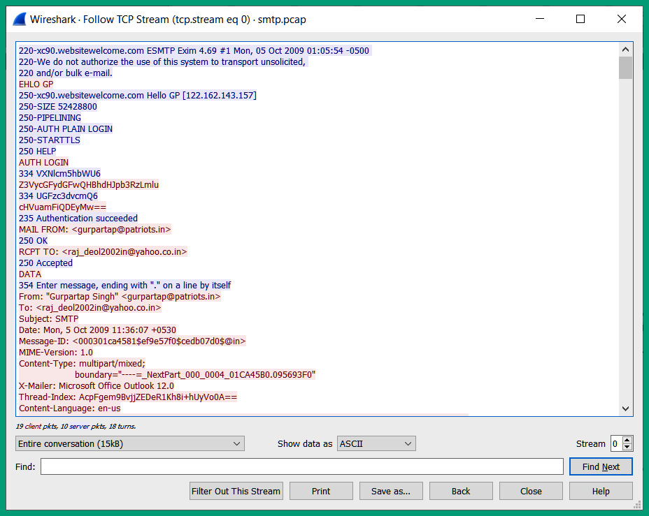
Figure 10.27 – TCP stream
As shown in the preceding screenshot, Wireshark took all the SMTP traffic, extracted the data from each packet in sequential order, and presented it in a dialog format. As shown, we can read the entire transaction in plaintext and all the email messages that were exchanged between the client and the server.
HTTP and HTTPS
Both HTTP and HTTPS are application-layer protocols that allow a web browser to communicate and interact with a web server. The main difference between these two protocols is that HTTP is an unsecure protocol that exchanges messages in plaintext, while HTTPS uses encryption to provide confidentiality.
The following screenshot shows the header of an HTTP packet:

Figure 10.28 – HTTP message
As shown in the preceding screenshot, the HTTP GET message contains a lot of fields that specify information about the sender, such as the following:
- User-Agent: Tells the web server about the sender's web browser
- Host: The sender's IP address
- Accept: The type of format the sender's browser will accept
- Accept-Language: The preferred language the sender will accept from a response
- Accept-Charset: The character set format and type the sender will accept from the server
- Accept-Encoding: The type of encoding that will be accepted by the sender from the web server
- Connection: Informs the web server of how to maintain the connection
As a cybersecurity professional, understanding the type of data that can be found within an HTTP/HTTPS header can help you identify whether a client had access to a malicious server to either upload or download files.
ARP
The Address Resolution Protocol (ARP) is responsible for resolving IP addresses to MAC addresses on a LAN. Since switches are unable to read layer 3 header information such as IP addressing, it's important that all nodes insert the accurate source and destination MAC addresses into their messages. Switches use layer 2 header details and the source and destination MAC addresses when making their forwarding decisions. However, threat actors can perform various types of cyber-attacks by leveraging the ARP network protocol.
The following screenshot shows an ARP flooding attack on a network:
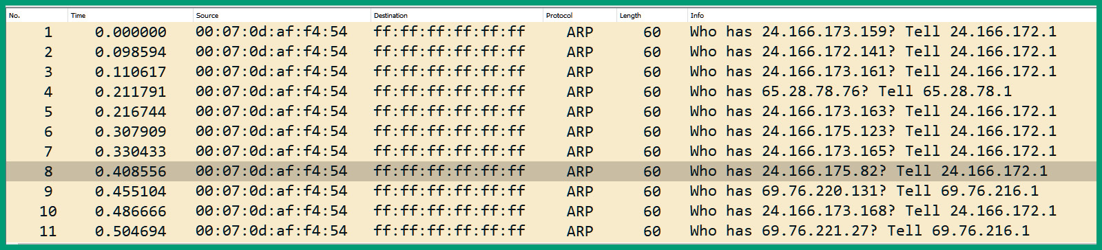
Figure 10.29 – ARP flooding attack
As shown in the preceding screenshot, we can see that a single client with a source MAC address of 00:07:0d:af:f4:54 is sending a flood of ARP request messages to all devices on the same layer 2 segment (FF:FF:FF:FF:FF:FF). As a cybersecurity professional, if you observe such volume and type of traffic on your network, it should be considered suspicious and worth investigating.
The following screenshot shows the protocol header of an ARP message using Wireshark:

Figure 10.30 – ARP protocol header
As shown in the preceding screenshot, we are able to obtain both the source and destination MAC and IP addresses. As a security professional, understanding how to find such information within network packets will be fruitful during your analysis and investigation of a network intrusion.
Having completed this section, you have learned how to identify various protocol headers within a packet. In the next section, you will gain hands-on skills on how to perform packet analysis using Wireshark.
Packet analysis using a PCAP file and Wireshark
Packet analysis is the technique of investigating details found within network traffic in an organization. Since devices send and receive packets between each other, the details found by analyzing the network traffic will provide statistics and in-depth information about all the conversations that are of interest to a security engineer. Such details will be host devices, protocols, file transfers, Voice over IP (VoIP) conversations, and so on. You'll be able to determine the most widely used network applications, the hosts that are sending and receiving the most network messages, file transfers, network errors and latency issues, and even perform network forensics to determine which event occurred on the network.
One of the most popular tools for performing packet analysis is Wireshark. Wireshark has been around for quite some time now and can capture traffic on many types of networks, such as wired, wireless, and mobile networks. To learn about packet analysis, you need to see Wireshark in action in the following lab exercise.
Lab – packet analysis using Wireshark
In this lab, you will learn the fundamentals of analyzing network packets using Wireshark. You will also learn how to identify the most used applications on a network, identify files that are transferred between a source and a destination, and extract files from a PCAP file using Wireshark.
To complete this hands-on exercise, please follow these instructions:
- Download and install Wireshark on your host computer. Wireshark can be found at https://www.wireshark.org/.
- We'll be using a sample capture that contains a lot of data. To download the sample capture, go to https://gitlab.com/wireshark/wireshark/-/wikis/SampleCaptures and download the http_with_jpegs.cap.gz file, as shown in the following screenshot:
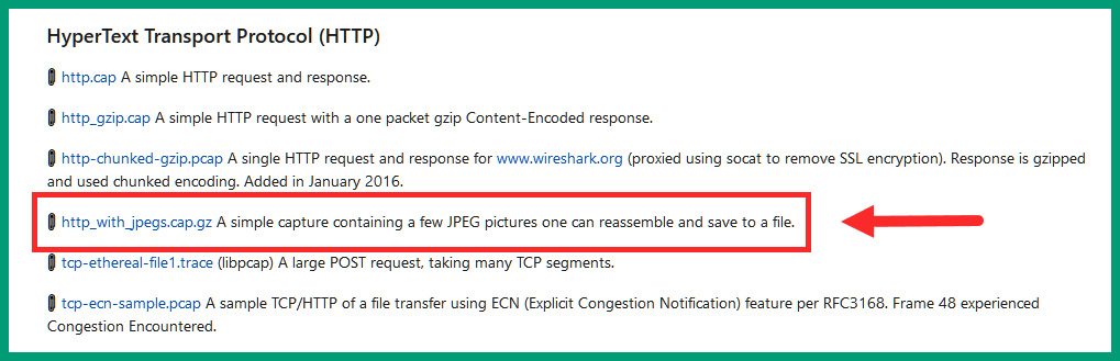
Figure 10.31 – Sample packet capture
- Once the http_with_jpegs.cap.gz file has been downloaded, use a tool such as 7-Zip (https://www.7-zip.org/) to extract the PCAP file.
- Once the file has been extracted open it using Wireshark, as shown in the following screenshot:
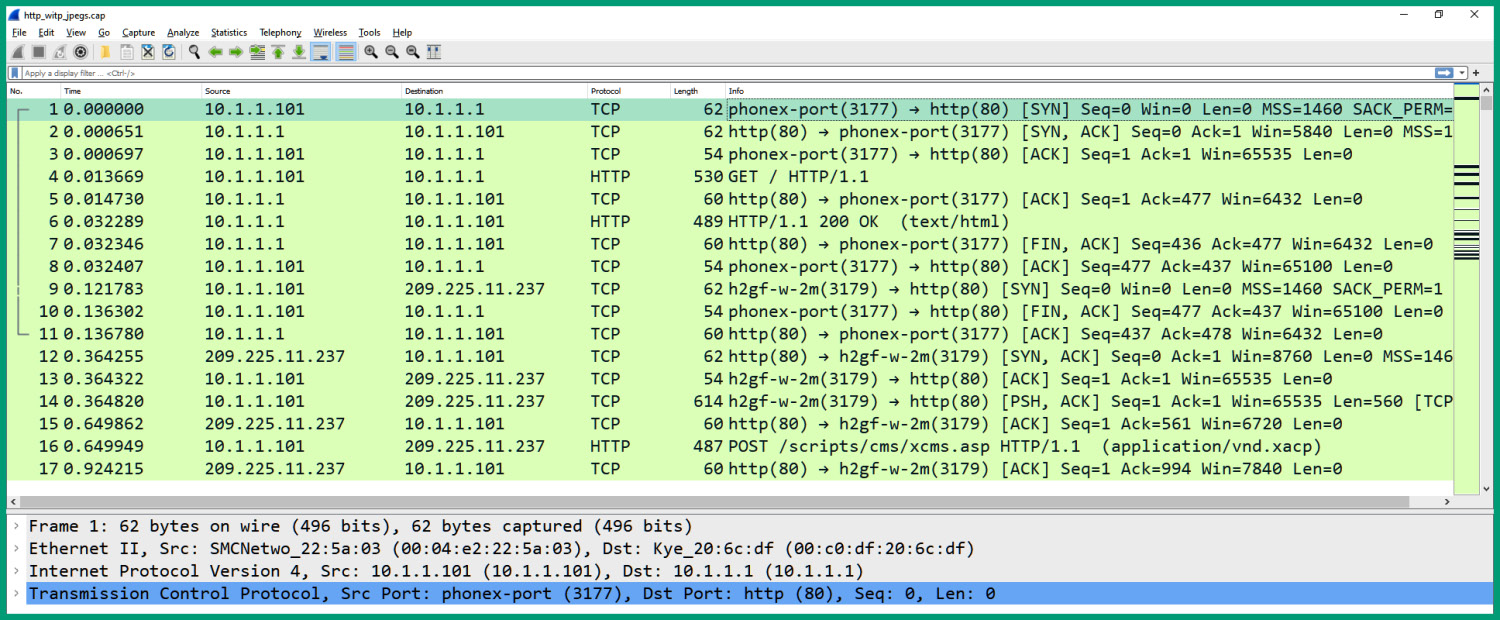
Figure 10.32 – Packet list pane
As illustrated in the preceding screenshot, Wireshark loads the sample capture and shows the packet number, absolute time (Time), source and destination IP addresses, source and destination port numbers, network protocol, packet length, and a brief summary about the packet.
- Click on packet #1 to get additional details about this packet, as illustrated in the following screenshot:

Figure 10.33 – Selecting a packet
As shown in the preceding screenshot, the packet details pane provides in-depth details about the selected packet. Expanding each row, you will be able to analyze each field within the packet itself.
- To view all the connections that occurred during the capture of this sample file, click on Statistics | Conversations, as shown in the following screenshot:

Figure 10.34 – Viewing network conversations
The following window will open and show a list of all network conversations that occurred, as shown in the following screenshot:
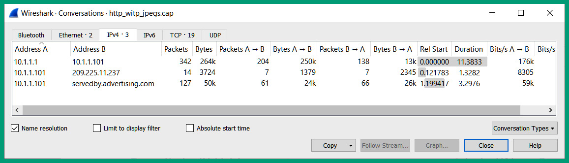
Figure 10.35 – Viewing host conversations
As shown in the preceding screenshot, you can see a list of conversations between a source and destination host and the total number of packets sent. Here, you can quickly identify the source and destination IP addresses between host devices.
- Next, click on the TCP tab to view a list of all the TCP connections, as shown in the following screenshot:

Figure 10.36 – Viewing TCP connections
As shown in the preceding screenshot, you are able to identify the source and destination IP addresses, source and destination service port numbers, and protocols between hosts who are exchanging messages. When you have finished exploring the data found within each tab, close the Conversations window.
- If you scroll down further on the packet list pane, you'll notice that packets #19, #20, and #21 are highlighted in red and black, as follows:
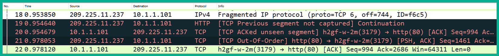
Figure 10.37 – Packets with errors
Wireshark has identified these packets as containing some type of error or warning on the network and has highlighted this on the interface.
- Click on packet #21 and expand the packet details pane, as shown in the following screenshot:
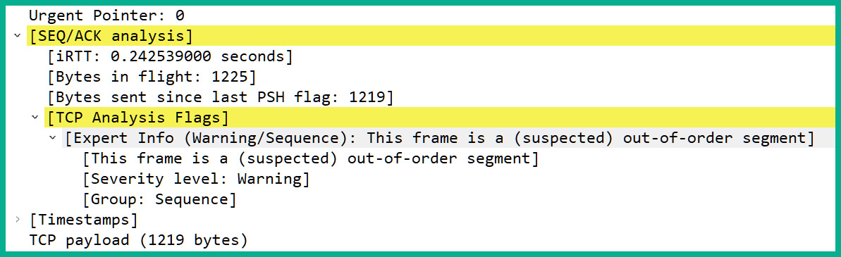
Figure 10.38 – Expanding the packet details pane
As shown in the preceding screenshot, Wireshark has cited an issue with this particular packet, as the frame is suspected to have been sent out of order. If you see many packets being flagged as out-of-order, this can be a networking issue or a security concern that an attacker is sending malicious code on your network while trying to avoid detection. Keep in mind that Wireshark is a network protocol analyzer and cannot stop an attack.
- A PCAP file contains all the files that are transferred between a source and a destination during the capturing process of the packets. To extract a file from a TCP stream, click File | Export Objects | HTTP…, as shown in the following screenshot:
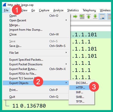
Figure 10.39 – Exporting objects
- Next, the HTTP object list window will open. You will see a list of all the files and their file types that were exchanged during the packet capture. To extract a file, select the file and click Save, as shown in the following screenshot:

Figure 10.40 – Extracting a file from a PCAP file
The following is a preview of the file that was extracted during this lab exercise:

Figure 10.41 – Image
Having completed this lab, you have gained the skills for identifying various key elements using Wireshark and have learned how to extract files from a PCAP file. This knowledge is very useful as if you have detected a malicious file that was sent between a source and a destination, you can extract the malicious file to perform malware analysis.
Summary
During the course of this chapter, you have gained the knowledge and skills to identify various fields found within networking protocols as they are associated with a network-based intrusion. Additionally, you are able to perform packet analysis and extract files from a packet capture using Wireshark. This skill is very useful when trying to identify which files were exfiltrated or downloaded during a cyber-attack. Lastly, you are able to compare traffic integration techniques, such as methods on capturing network traffic as it passes along a network. The capturing of inline network traffic helps a cybersecurity professional to perform real-time traffic analysis to determine suspicious activities between users, appliances, and devices.
I hope this chapter has been informative for you and is helpful in your journey toward learning the foundations of cybersecurity operations and gaining your Cisco Certified CyberOps Associate certification. In the next chapter, you will learn the fundamentals of security management and techniques that can help reduce risk within an organization.
Questions
The following is a short list of review questions to help reinforce your learning and help you identify areas that require some improvement. The answers to these questions can be found in the Assessments section at the end of this book:
- Which type of device provides automation for handling security incidents?
A. SIEM
B. IPS
C. SOAR
D. Firewall
- How can a firewall filter traffic on a network?
A. Through the source IP address
B. Through the service port number
C. Through the protocol
D. All of the above
- How can a security professional capture traffic on a network?
A. By configuring SPAN
B. By configuring Spanning Tree Protocol (STP)
C. By configuring port security
D. None of the above
- Which of the following alert types means there is an intrusion on the network but no alarms were triggered?
A. False positive
B. False negative
C. True positive
D. True negative
- Which of the following is not an element of the five tuples?
A. Destination server port number
B. Protocol
C. Source IP address
D. Device hostname
Further reading
To learn more about network analysis and intrusion policies, see the following:
- Network analysis and intrusion policy basics: https://www.cisco.com/c/en/us/td/docs/security/firepower/650/configuration/guide/fpmc-config-guide-v65/overview_of_network_analysis_and_intrusion_policies.html