Chapter 2: Exploring Network Components and Security Systems
On all networks, there are many network protocols and services that help to exchange data and access resources. These protocols and services contain vulnerabilities that allow an attacker to leverage the weaknesses found therein. Understanding how these technologies work will provide you with a clear understanding of their operations and how to protect your network from cyber-attacks.
Throughout this chapter, you will learn about various networking technologies, protocols, and services, and how they all work together to forward your messages, such as data between your device and the destination. As a cybersecurity professional, it is essential to fully understand how network devices and protocols function. Upon completing this chapter, you will be able to fully understand the networking aspects of cybersecurity, something that many professionals struggle to grasp.
In this chapter, we will cover the following topics:
- Exploring various network services
- Discovering the role and operations of network devices
- Describing the functions of Cisco network security systems
Now that we are aware of the outcomes we are set to achieve, let's dive into the chapter!
Technical requirements
To follow along with the exercises in this chapter, please ensure that you observe the software requirement of having the Wireshark application installed on your computer. To obtain a copy of Wireshark, please visit https://www.wireshark.org.
Link for Code in Action video https://bit.ly/3evbHLx
Exploring various network services
As an up-and-coming cybersecurity professional, it's essential to understand the functions and roles of various network services and protocols. Many network protocols and services were not designed with security in mind. Back in the early days of computer networking, many organizations created protocols to assist with moving data between a source and destination. As time went on, computer wizards, or wizzes, began exploring and exploiting the functions of many network protocols and soon started to discover vulnerabilities within their design.
Today, hackers are continuing the same trends by looking for weaknesses within many protocols and services. Although most people may think that vulnerabilities exist only in a software application or even an operating system, security weaknesses do exist in many network protocols and hackers are exploiting them to assist with their intentions.
Therefore, by understanding the characteristics and functionalities of various network services, you will be able to better protect your network from hackers. In this section, you will explore the functions of the Address Resolution Protocol (ARP), Domain Name System (DNS), and the Dynamic Host Configuration Protocol (DHCP).
Address Resolution Protocol
ARP is a Layer 2 network protocol used to resolve Internet Protocol (IP) addresses to MAC addresses on a network. This protocol is vital for helping devices, whether it's a computer, smartphone, or even a router, to determine how to forward a message to a destination.
Many individuals may not regard ARP as an important role in all networks simply because it's sometimes considered to be less popular compared to the others, such as IP, TCP, and UDP.
Many Local Area Networks (LANs) are mostly made up of switches. These network switches operate at only Layer 2 of the OSI reference model and the TCP/IP protocol suite, which means they are only able to see the contents of a message between Layer 1 and Layer 2. To put it simply, switches are only able to see MAC addresses, not IP addresses. Imagine you are sending a message from your computer to another device on your network. The message is sent to the switch, which then forwards it to the destination. However, switches make their forwarding decision based on MAC addresses and not IP addresses.
You're probably thinking, isn't it the case that all devices have an IP address, and isn't this used for network communication? It is true that IP addresses are akin to a street address and are used for communication on a TCP/IP network, but switches are not able to read the IP. This means it is vital, before one device sends a message to another, that the sender knows the MAC address of the destination and inserts it as a Layer 2 header on the frame, such that switches can use the source and destination MAC addresses found within frames to make their forwarding decisions.
What if a device does not know about the MAC address of a destination: how will it forward messages? In this event, Device-A (sender) may already know the destination IP address of the intended recipient, Device-B. The sender, Device-A, will broadcast an ARP Request message (broadcast) to all devices within the LAN, asking who has assigned the destination IP address. Only the device with the correct destination IP address will respond with its MAC address back to Device-A.
The following diagram shows this process of ARP request and ARP reply messages:
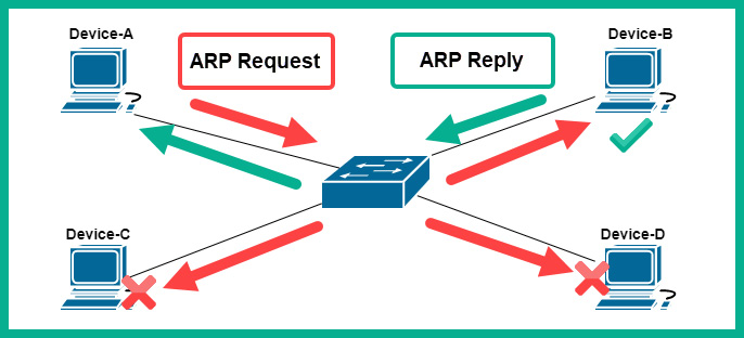
Figure 2.1 – ARP messages
Once Device-A records the MAC address of Device-B within its ARP cache, it will then insert the proper Layer 2 header containing the source MAC address of Device-A and the destination MAC address of Device-B.
The arp –a command can be used on Windows and Linux operating systems to check the ARP cache:
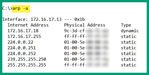
Figure 2.2 – ARP cache on Windows
The following snippet shows the ARP cache on an Ubuntu (Linux) machine:
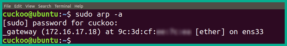
Figure 2.3 – ARP cache on Linux
An operating system such as Microsoft Windows retains the contents of its ARP cache for a total of 5 minutes before removing entries due to inactivity. To view the ARP cache on a Cisco IOS router, use the show ip arp command, as shown here:
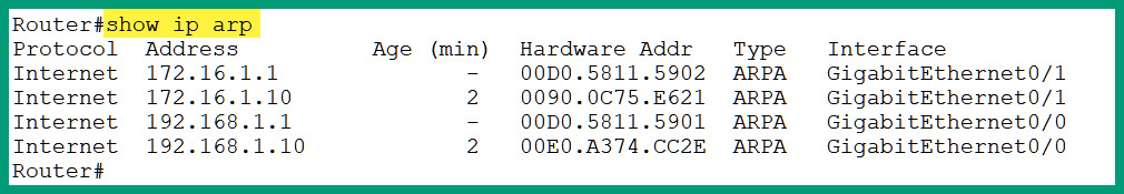
Figure 2.4 – Viewing the ARP cache on a Cisco device
You now understand the importance of ARP on networks and have discovered how to view ARP entries on devices. Next, you will explore an important IP service that is commonly used by all devices on a private and public network, known as Domain Name System (DNS).
Domain Name System
DNS was designed with the primary function of resolving hostnames to IP addresses. Without DNS on a network or even the internet, we will need to know and remember all the IP addresses of each server and device we want to access. Imagine you want to visit Cisco's website to learn more about their products, services, and certification tracks. Firstly, you will need to know the IP address of Cisco's web server and enter it into the address bar of your web browser to access the home page. It could be very challenging to remember the IP addresses of all the web servers you want to visit, as I'm sure you have commonly visited hundreds or even thousands of web servers in the past without knowing their corresponding IP addresses.
DNS servers are devices that contain various records that are mapped with an associated IP address for domain names. There are many publicly available DNS servers on the internet, some of which provide improved speed and performance, while others are able to provide security, such as malware filtering.
The following is the sequence that a host device uses to acquire the IP address of a host system:
- For every website URL or domain, or a system such as a computer, it sends a DNS query to its configured DNS server asking for the IP address of the hostname.
- Once the DNS server finds the record within its database, it will respond with a DNS reply back to the computer.
- Then, the computer will use the IP address to connect to the web server domain.
The following diagram provides a visual representation of a computer using the DNS service:

Figure 2.5 – DNS query
The following are some publicly available DNS service providers:
- Google Public DNS: https://developers.google.com/speed/public-dns
- Cloudflare DNS: https://1.1.1.1/
- Cisco OpenDNS: https://www.opendns.com/
- Quad9: https://www.quad9.net/
A managed DNS from a trusted provider can help reduce the risk of finding malware and other various cyber-attacks on your corporate network. One such solution is Cisco Umbrella; this is Cisco's premium DNS solution, which not only provides the essential hostname-to-IP address resolution compared with other DNS providers, but also actually does a lot more with a focus on security.
Tip
To learn more about Cisco Umbrella, you can visit the following URL: https://umbrella.cisco.com/.
The following is a list of the various types of records that are stored on a DNS server:
- A: This record is used to map a hostname to an IPv4 address.
- AAAA: This record is used to map a hostname to an IPv6 address.
- MX: This record is used to indicate the mail exchange servers for a domain.
- NS: This record indicates the name servers for a given domain.
- PTR: This record maps an IP address to a hostname.
- RP: This record is used to indicate the person responsible for a domain.
- CNAME: This record provides the canonical name or alias for a domain or hostname.
- TXT: This record allows you to set a string of text as a DNS record on the server. It is usually created to prove the owner of a domain.
Now that you have an understanding of the need for, and benefits of using, a DNS, let's dive into some practical labs on performing DNS lookup using the NsLookup tool on Windows and DNS analysis using Wireshark, which are coming up next.
Lab – performing DNS lookup
In this lab, you will learn how to perform DNS lookup by querying a publicly available DNS server to retrieve records for a domain on the internet.
To begin this exercise, please observe the following instructions:
- Open Windows Command Prompt.
- Type the nslookup command and hit Enter. This will allow you to access the built-in tool interactive menu. The details that appear will be your pre-configured or default DNS server for your computer:
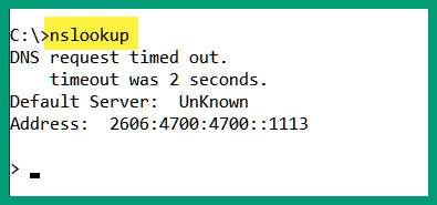
Figure 2.6 – Default DNS configurations
- Next, let's change the DNS server through which we want to send our DNS queries by using the server command. For this exercise, we will use Google's public DNS server, 8.8.8.8, as shown here:
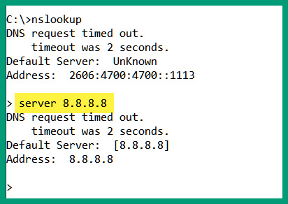
Figure 2.7 – Changing the DNS server for queries
Please keep in mind that this does not change the default settings on your operating system. It only changes the server to query using just the NsLookup tool.
- Type the www.cisco.com hostname and hit Enter:

Figure 2.8 – Performing a DNS query
By default, nslookup will provide the A record details, such as the IPv4 address for the www.cisco.com hostname.
- To change the record type that you want to query, use the set type=<record type> command. Let's use the set type=mx command to retrieve the mail exchange records for the domain.
- Next, enter a domain name and not a hostname to retrieve the record type. Let's retrieve the MX records for www.cisco.com, as shown here:

Figure 2.9 – Retrieving the MX records
By changing the set type value and entering a hostname or domain name, you will be able to perform DNS queries to your specified DNS server.
During the course of this hands-on exercise, you have learned how to perform DNS queries for various types of DNS records using a public DNS server. In the next lab, you will take a deeper dive into understanding the contents of DNS messages that are exchanged.
Lab – DNS analysis using Wireshark
In this lab, you will learn how to perform DNS analysis on DNS traffic that is being exchanged between a host and a DNS server.
To begin this exercise, please observe the following instructions:
- Go to https://gitlab.com/wireshark/wireshark/-/wikis/SampleCaptures and download the dns.cap file onto your desktop.
- Use Wireshark to open the dns.cap file.
If there are other traffic types shown in the capture file, type dns in the display filter bar and hit Enter. This will allow Wireshark to only show DNS traffic, as shown here:
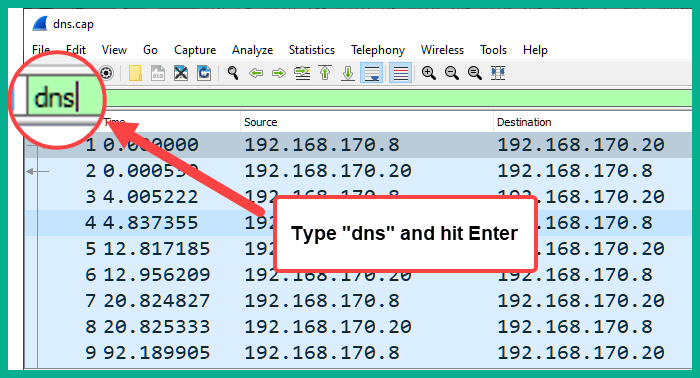
Figure 2.10 – Filtering the DNS traffic view on Wireshark
- Click on Packet #9 to observe the DNS query details sent from 192.168.170.8 to the DNS server at 192.168.170.20, as shown here:
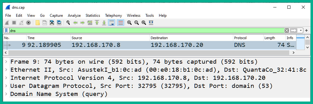
Figure 2.11 – Observing the DNS query
In the details pane of the packet, you will notice the source and destination IP addresses, as well as the source and destination service port numbers.
- Expand the application layer of the message in the details pane. You will see that the DNS query is asking for the Type A record for the www.netbsd.org hostname, as shown in the following screenshot:
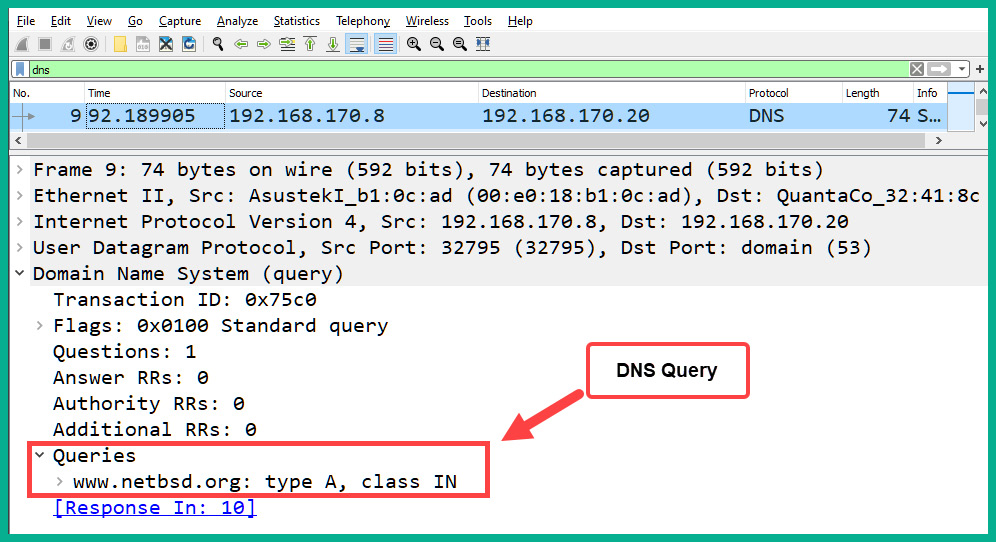
Figure 2.12 – DNS query details
- Next, click on Packet #10, which is the DNS reply or DNS response for Packet #9. Expand the application layer of the details pane for Packet #10, as shown in the following screenshot:
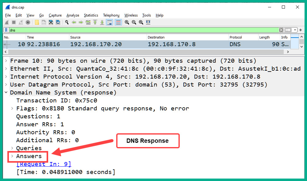
Figure 2.13 – DNS response details
In the DNS reply or DNS response message, there is an additional field that is inserted by the DNS server. It is called Answer. This field contains the response for the DNS query.
- Expand the Answer field to find the response for the Type A record for the www.netbsd.org hostname, as shown in the following screenshot:
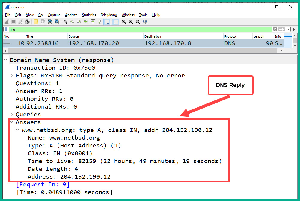
Figure 2.14 – DNS reply for the Type A record
As indicated, the DNS reply contains the 204.152.190.12 IPv4 address for the www.netbsd.org hostname.
By completing this exercise, you have gained skills that are essential for analyzing DNS traffic packets as they are transmitted across a network. Do take the extra time to obverse the contents within the dns.cap file using Wireshark.
In the next section, you will learn about another important network service, Dynamic Host Configuration Protocol (DHCP), and its features.
Dynamic Host Configuration Protocol
DHCP is configured as an IP service on networks to automatically provide an available IP address to client devices. With DHCP, a network administrator does not manually have to assign or configure IP addresses to clients on an enterprise network. The network administrator can simply implement a centralized DHCP server, configured with a pool of addresses and other IP settings that can automatically be given to any client connected to the network.
Using DHCP on a network will provide the following benefits:
- It will improve the efficiency of the distribution of IP addresses to end devices.
- It will prevent the duplication of assigning the same IP address to more than one device.
- It will allow a network administrator to keep an account of IP address assignment to devices by monitoring their MAC addresses.
To gain a better understanding of how DHCP works on a network, let's take a look at the process of the DHCP four-way handshake, which occurs each time a client device is connected to a network with an available DHCP server.
When a client is connected to a network, the following process occurs:
- The connected client will automatically attempt to find a DHCP server on the network. It will broadcast a DHCP discover packet with the details shown in the following screenshot:
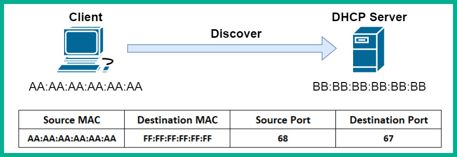
Figure 2.15 – DHCP discover packet
- Once a DHCP server exists on the network, it will receive and process the incoming packet from the client. It will respond to the client with a DHCP offer packet, which contains an available IP address and other configurations for the client to communicate on the network. The following screenshot shows the contents of the reply from the DHCP server:
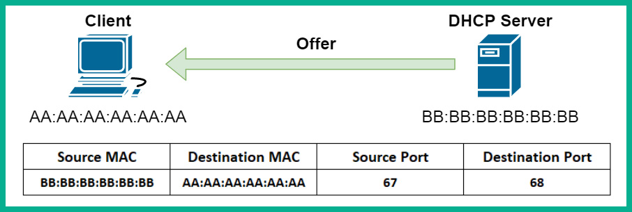
Figure 2.16 – DHCP offer packet
- The client, upon receiving the reply from the DHCP server, will check the contents of the message. Once the content is verified as being OK, it will respond with a DHCP request packet to confirm that it will keep and use the IP address for the duration of the lease from the DHCP server. The following screenshot shows a visual representation of the packet learning the client:
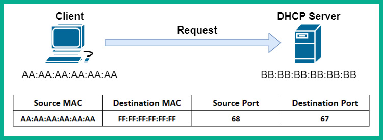
Figure 2.17 – DHCP request packet
- Lastly, DHCP will respond with a DHCP acknowledgment packet to confirm with the client the leasing of the IP address assigned to it. The following screenshot shows the DHCP server responding to the client on the network:
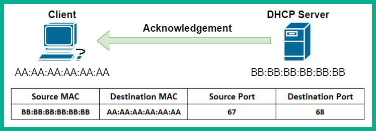
Figure 2.18 – DHCP acknowledgment packet
Now that you have completed this section, you are able to describe the functions and roles of the DHCP, DNS, and ARP network protocols. In the next section, you will learn about various network devices and their purpose in building an enterprise network.
Discovering the role and operations of network devices
As a soon-to-be cybersecurity professional, it's important to understand the role and operations of network devices. Such information is essential to better understand how hackers are able to compromise a network and the devices on it. Furthermore, hackers are able to take advantage of vulnerabilities found within many network protocols and use our network devices to assist with their malicious intentions.
In this section, you will learn about various networking devices that are commonly implemented within an enterprise and learn how they make their decisions on forwarding messages between a source and destination.
Hubs
Hubs are very old network devices that were used to interconnect end devices, but they are no longer used on modern networks. A hub allows end devices to interconnect and exchange messages between a source and destination. However, a hub does not operate or function like network switches.
To get a better idea of how a hub functions, let's take a look at the following diagram:
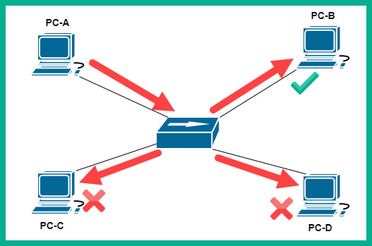
Figure 2.19 – Hub
Imagine PC-A wants to send a message to PC-B. PC-A will create the message and send it to the hub; the hub will accept the signal (message) and broadcast the message (signal) out to all interfaces except the port it originally received the message from. Therefore, the message is sent to all the other devices, PC-B, PC-C, and PC-D. Since the message was not intended for PC-C and PC-D, they both discard the message, while PC-B will accept and process the message.
To put it simply, a hub will accept an incoming signal and rebroadcast it out to all the other ports. This is simply how a hub operates on a network. In the early days of computer networking, this was not too much of an issue. However, as more devices started to be connected and networks grew continuously, hubs began to be an issue. Since hubs are sending messages to unintended destinations, this creates a security concern, such that a user may receive confidential information unintentionally on the network. For this reason, hubs are considered to be a Layer 1 device as all they do is repeat a signal at the physical layer.
Since a hub accepts an incoming signal and rebroadcasts it out of all the other ports, all connected devices are said to be on a single broadcast domain. A broadcast domain is defined as a logical segmentation of the network that allows a device to send a broadcast message that will be heard by all other devices. Additionally, hubs are also a single collision domain.
Another issue exists when two or more end devices are transmitting at the same time on a hub network. Hence, a message collision occurs between two devices when sending a signal on the network at the same time. On a hub network, only one device is able to transmit a message at a time. This creates a network performance issue, such that each device has to take turns in using the network to send and receive messages between other devices. These reasons have rendered the hub obsolete in the networking industry.
To solve this issue of end devices randomly placing signals on the hub network, Carrier Sense Multiple Access/Collision Detection (CSMA/CD) is implemented on computers. Carrier sense enables end devices, such as computers, to check the media, such as the network cable (wire), for any signals that may be passing across, while multiple access indicates that there are multiple devices that wish to access the media (wire) at the same time. Collision detection is the mechanism that enables computers to check the media for any incoming signals when sending their messages. If a signal is detected, the computer will wait and check the media again. If no signals are detected on the media, the computer will proceed to send its message on the wire.
Switches
Switches are smart devices compared with hubs on a network. Switches are the network intermediary device that allow end devices, such as computers, servers, and printers, to connect to the other devices on the network and share resources. Unlike hubs, switches do not rebroadcast an incoming signal on any of their ports (interfaces). Rather, a switch operates at Layer 2 of the TCP/IP protocol suite and makes its forwarding decision based on the destination MAC address found in the Layer 2 header of an incoming frame.
When any frame enters an interface (port) on a switch, the switch inspects the Layer 2 header for the source and destination MAC addresses. It will store the source MAC address in its Content Addressable Memory (CAM) table and map it to the interface that the frame was received on. Therefore, in the future, if the switch receives a frame with a certain MAC address, it will perform a lookup on its CAM table to determine where the destination MAC address resides. Once found, the switch will bind the frame directly to the destination.
The following screenshot shows the contents of the CAM table on a Cisco switch:
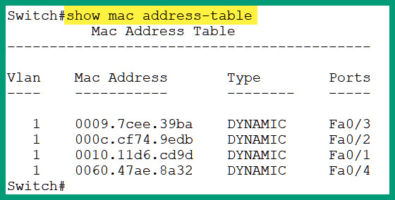
Figure 2.20 – Viewing learned MAC addresses on a Cisco switch
As shown in the preceding screenshot, you will notice that there are MAC addresses that are learned on various interfaces and the switch has assigned the interface details to each MAC address.
As you learned in the previous section, all interfaces (ports) on a hub function as a single broadcast domain. Additionally, if two or more devices send a signal at the same time, a collision occurs. Therefore, all interfaces on a hub are on a single collision domain. A switch is designed such that each individual port is its own collision domain. This means that if a switch has multiple devices connected to it, they can all send and receive messages without any network collisions occurring. Furthermore, it's recommended that only one should be connected to a single switch interface, for example, one computer per switch interface.
However, if an end device such as a computer sends a Layer 2 broadcast message, with the FF-FF-FF-FF-FF-FF destination MAC address, the switch will forward the Layer 2 broadcast message out of all ports except the interface it was received on. This creates a broadcast domain on the switch.
Additionally, if a host device wants to send a message to another host of which the destination MAC address is unknown, the source device will use ARP to send an ARP request message to all devices on the same broadcast domain by using a destination MAC address of FF-FF-FF-FF-FF-FF.
Layer 3 switches
As you have already learned, switches commonly operate at Layer 2 of the TCP/IP protocol suite and are able to read Layer 2 header information only, nothing beyond this. As the networking industry continues to develop new technologies, Cisco has created Layer 3 switches. These Layer 3 switches can operate both at the internet (Layer 3) and data link (Layer 2) layers of the TCP/IP protocol suite. These switches can perform various Layer 3 functions, such as routing, and are commonly implemented in medium to large enterprise networks and even data centers.
Routers
Routers are Layer 3 devices that are used to interconnect two or more different networks. This means that a router can be used to interconnect different IP networks or even networks that support different media types, such as fiber and copper cabling. A router is able to read the information found within an IP address, such as the Layer 3 header details. When a packet enters a router's interface, the router will inspect the destination IP address and then check its routing table to locate a suitable route.
Once a route is found, the router will then forward the packet to its intended destination. If a route is not found, the router will return a Destination unreachable message to the sender, informing it that the router is unable to locate a route for forwarding the packet.
Important note
Routers do not forward Layer 2 broadcast messages, such as frames, that contain a destination MAC address of FF-FF-FF-FF-FF-FF.
The following diagram shows a router interconnecting two different networks:

Figure 2.21 – Router connecting networks
Each end device is usually configured with a default gateway. This is the doorway to beyond the local IP subnet. As shown in the preceding diagram, PC-1 is using 192.168.1.1 as its default gateway. Therefore, if PC-1 wants to send a message to a host beyond its own network, it will forward the message to its default gateway, the router. The router will then check its routing table and forward the packet accordingly to the destination.
Wireless Access Point (WAP)
As more and more people and organizations are acquiring mobile devices, such as smartphones, tablets, and laptops, the need for wireless networks is also growing. One such device that allows us to bridge the gap between a wired and a wireless network is a Wireless Access Point (WAP). A WAP is a device that allows network administrators to create wireless networks, thereby allowing Wi-Fi-capable devices to interact with a wired network.
The following diagram shows a WAP on a small network:
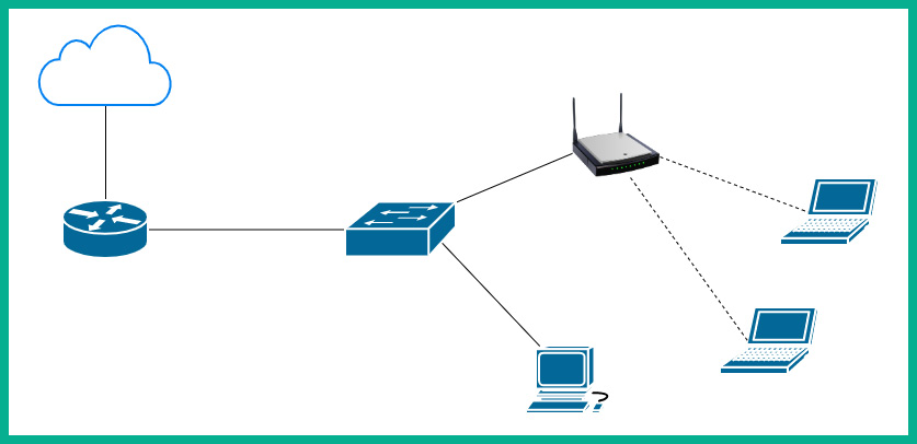
Figure 2.22 – WAP
To put it simply, WAPs are used to extend the physical wired network into a wireless network, allowing users such as employees to roam around the office with their mobile device and still be able to access the network resources on the corporate LAN. WAPs use the IEEE 802.11 standard, which describes the usage of both the 2.4 GHz and 5 GHz radio frequencies and channels for wireless communication.
On IEEE 802.11 wireless networks, network collisions can occur similarly to a wired network with a hub. An access point operates a bit like a hub on the network. When a message is sent to the access point, it will regenerate and send the message to all other connected clients. Furthermore, collisions can occur if two or more clients are transmitting their messages at the same time. To prevent collisions on a wireless network, mobile clients use Carrier Sense Multiple Access/Collision Avoidance (CSMA/CA).
With CSMA/CA, each mobile client will send a message to the access point to ask whether the media, which is the airwave, is free and available. The access point will respond to the client, informing it to proceed and send its message, or that the channel is busy at the moment and to try again later. To put it simply, each wireless client asks permission of the access point before they transmit their message across the network.
Wireless LAN Controller (WLC)
On an enterprise network, a network professional may be tasked with administering and managing the entire wireless network for an organization. Within the organization, there may be dozens of access points that are located at various branch offices.
Managing the wireless network may include the following tasks:
- Creating, changing, and/or removing a Service Set Identifier (SSID) or wireless networks
- Modifying the wireless network settings
- Modifying the wireless security configurations
- Adjusting the power levels on the antennas
- Detecting rogue access points
As a network administrator, if a change has to be made on the wireless network, you can manually log on to each access point and make the necessary change, one at a time. This task seems to be a bit time-consuming due to the manual and repetitive nature of the process, since the change has to be done on all devices within the organization. A Wireless LAN Controller (WLC) can be used to centrally manage all the WAPs within your entire organization using a simple and simplified dashboard.
The following diagram shows a WLC centrally deployed to manage multiple access points:

Figure 2.23 – Deployment of a WLC
By implementing a WLC on the network, a network administrator can simply log in to the WLC user dashboard, create or modify wireless networks, control each access point at any location, and manage the wireless security, all from a centralized location.
An example of a cloud-based solution is Cisco Meraki. Cisco Meraki provides a subscription-based service for accessing a WLC in the cloud to manage the Cisco Meraki devices, such as their switches and access points. This type of service allows users to simply pay a subscription for the cloud-based controller, being able to manage their access points in real time, gather statistics, and manage security.
By completing this section, you have acquired the skills and knowledge necessary to identify the functions of various networking devices and understand how they forward messages across a network. Such knowledge is important for a cybersecurity professional as hackers attempt to manipulate the functions of these networking devices during their attacks.
Describing the functions of Cisco network security systems
In this section, you will learn about various Cisco security solutions and how they are used to protect an enterprise network and its users from cyber-attacks and threats.
Firewall
A firewall is a security appliance that is designed to prevent malicious traffic from entering or leaving a network. Cisco's Next-Generation Firewall (NGFW) is designed to offer the latest protection to users by inspecting all inbound and outbound network traffic. It is important that organizations realize the need for this security appliance as it is typically implemented at the network perimeter, as shown in the following diagram:
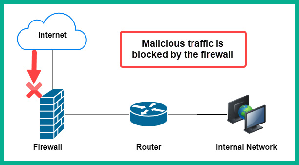
Figure 2.24 – Firewall deployment
Firewalls are not only implemented at the network perimeter; they are also implemented with networks to provide advanced filtering of traffic. Furthermore, NGFWs are designed to provide additional security services, such as Data Leakage Prevention (DLP), which allows a security administrator to restrict employees from sending sensitive or confidential files outside the company's network. NGFW supports Deep Packet Inspection (DPI), which enables the firewall to decrypt any encrypted packet and inspect the data at the application layer in the event that there is any hidden malicious code. Additionally, NGFWs are able to provide Virtual Private Networks (VPNs), which allow an organization to connect remote offices via a site-to-site VPN and even allow remote workers to securely access the corporate network via the internet using a remote access VPN.
Cisco Intrusion Prevention System (IPS)
A firewall may not have the capabilities to inspect certain traffic types, such as Structured Query Language (SQL). To assist with the inspection of other traffic types, an Intrusion Detection System/Intrusion Prevention System (IDS/IPS) can be implemented on your internal network. The objective of implementing an IDS or an IPS is simply to reduce the attack surface of your assets, including end devices such as servers.
The following diagram shows the deployment model for an IPS:
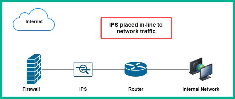
Figure 2.25 – IPS deployment model
The IPS is deployed between the firewall appliance and the internal network, simply to catch anything that has been missed by the firewall that is originating from the internet. Furthermore, the IPS is placed in-line such that network traffic has to flow through it. This implementation type is very beneficial in that if malicious traffic is detected by the IPS, it will immediately block the traffic and send an alert, thereby making the IPS a proactive device.
The IDS also has the ability to inspect and detect malicious traffic, but does not have the mechanisms to block the threat as it is happening. This means that the IDS is a reactive device simply because it can detect and alert but not block the attack.
The following diagram shows the deployment model for an IDS:

Figure 2.26 – IDS deployment model
As shown in this diagram, the IDS does not sit in-line with network traffic, but rather is connected to a switch on the network. The switch is configured with a SPAN port or a mirrored interface to send a copy of all traffic entering the switch to the IDS appliance. The IDS appliance will simply inspect all the incoming traffic, looking for intrusions, and will send an alert only if it detects a threat.
Both IPS and IDS can be implemented on the network and/or on host devices. These types of implementation are commonly referred to as the following:
- Network-Based Intrusion Detection System (NIDS)
- Network-Based Intrusion Prevention System (NIPS)
- Host-Based Intrusion Detection System (HIDS)
- Host-Based Intrusion Prevention System (HIPS)
As you have seen in the previous diagrams, those were network-based implementations of both the IDS and IPS appliances. The benefit of using a network-based solution is that it has the ability to detect and/or prevent the threats on a network itself. However, the host-based implementation is where each host device, such as a computer, has its own HIDS or HIPS installed on the local system. With HIDS/HIPS, you will be able to detect and prevent malicious traffic from entering or leaving the individual host machine.
Both IDS and IPS use the following methods to identify intrusions:
- Signature-based: This method inspects the traffic, looking for a pattern that matches malicious code or a threat.
- Protocol analysis: In this method, the sensor inspects all the fields within the application layer protocols within the flow of network traffic. If any protocol field appears to not be complying with the standard format, the sensor will trigger an alarm.
- Heuristic or anomaly-based: This method looks for anything that is out of the ordinary on the network. For example, if an attacker is creating a lot of half-open connections by sending TCP SYN packets with another device and completing or closing the sessions, the sensor will trigger an alarm.
- Global threat correlation: Cisco devices all connect to Cisco's security intelligence cloud, which enables devices to share information and receive updates from Cisco's security team in real time. Cisco's global security team is known as Cisco Talos.
Cisco IDS and IPS security appliances provide various types of alerts or alarms. The following are the various types of alerts that can occur on an IDS/IPS appliance:
- False positive: An alarm is triggered, but no threats exist.
- False negative: No alarm is triggered, but a threat does exist.
- True positive: An alarm is triggered, and a threat does exist.
- True negative: No alarm is triggered, and no threat exists.
Your objective as a security professional is to ensure that your IDS/IPS is tuned to provide mostly true positive and true negative alert types. These alerts will ensure that security appliances are working as expected and that your security analysts receive alerts involving intrusions.
Web Security Appliance
Another security appliance is Cisco's Web Security Appliance (WSA), which is deployed on-premises to help protect a user in an organization's web traffic. WSA is a web security solution that will filter both inbound and outbound web traffic. WSA has the ability to provide URL filtering and Data Loss Prevention (DLP) on employees sending confidential files outside the company's domain. It also has the ability to inspect inbound or returning traffic from the internet to the internal client. WSA will inspect all traffic to ensure that it is not malicious in nature.
Additionally, Cisco has a cloud-based solution, which is Cloud Web Security (CWS). The roles and functions of both WSA and CWS are the same, the only difference being that WSA is deployed locally within the organization's network, while CWS is deployed on a data center in the cloud.
Email Security Appliance
Cisco's Email Security Appliance (ESA) is a security appliance that has an important job in filtering malicious inbound and outbound emails. ESA provides various levels of filtering email messages to prevent various types of threats, including the following:
- Spam
- Malware
- Phishing
- Spear phishing
The objective is to ensure that all inbound email messages are sent to the ESA security appliance before they are delivered to your users' inboxes. ESA will perform various types of security checks and filtering, including the following:
- Reputation filters
- Message filters
- Anti-spam
- Anti-virus
- Advanced Malware Protection (AMP)
- Content filters
- Outbreak filters
These inbound filters ensure that the email is safe before it reaches your inbox, thereby adding a layer of security to your email messages. Additionally, ESA also has the ability to inspect outbound email messages from your organization to ensure that users are not spreading malware or leaking sensitive information. The following are the various security checks that are performed by ESA on outbound email messages:
- Messaging filters
- Anti-spam
- Anti-virus
- AMP
- Content filters
- Outbreak filters
- DLP
Similar to the CWS appliance, Cisco also has a cloud-based solution for ESA, which is known as Cisco's Cloud Email Security (CES). Both ESA and CES have the same roles and functions, although their deployment does vary, as one is implemented locally while the other is implemented in the cloud.
Cisco Advanced Malware Protection
The AMP security solution is an engine and application that can be installed on endpoints to help detect and block malware. Cisco AMP is already integrated with other Cisco security solutions, such as NGFW, Next-Generation Intrusion Prevention System (NGIPS), Cisco email security appliances, such as ESA and CES, and web security appliances, such as WSA and CWS.
With AMP integrated into all these products, it's easier to detect and block malware on the network itself. With AMP on your endpoint or security appliances, it can perform analysis and sandbox code that appears to be malicious, perform real-time threat management, and provide trajectory information about any threats it has detected, providing information regarding where the malware originated and how it has been spreading across the network.
As with all of Cisco's security solutions, AMP receives its security information from the Cisco global threat intelligence cloud and Cisco Talos so as to always have the latest updates and information about any new and emerging threats out there in the wild.
Having completed this section, you have learned about the roles and functions of various Cisco security solutions and how they work to keep users safe and reduce the attack surface within an enterprise's network.
Summary
During the course of this chapter, you have gained the essential skills to perform DNS inspection, using one of the most popular protocol analyzers within the industry – Wireshark. To conclude the chapter, we discussed the role and functionality of network devices and security appliances and how they work together to forward traffic between devices and to filter malicious traffic.
I hope this chapter has been informative for you and will be helpful in your journey toward learning the foundations of cybersecurity operations and gaining your Cisco Certified CyberOps Associate certification.
In the next chapter, Chapter 3, Discovering Security Concepts, you will learn how to get started with using a cybersecurity approach to secure your assets.
Questions
The following is a short list of review questions to help reinforce your learning and to help you identify areas that may require improvement. The answers to these questions can be found in the Assessments section at the end of this book:
- Which of the following devices is used to help protect employees from phishing attacks?
A. ESA
B. WSA
C. NGFW
D. AMP
- Which of the following devices can detect intrusions and send an alert but does not stop the threat?
A. AMP
B. IPS
C. IDS
D. NGFW
- Which of the following is able to sandbox potential code to determine its intent?
A. IPS
B. AMP
C. IDS
D. NGFW
- Which type of device is used to centrally manage all the WAPs within a network?
A. Router
B. NGFW
C. WLC
D. Switches
- Which security appliance can help prevent employees from sending sensitive files outside the corporate network via emails?
A. NGFW
B. WSA
C. ESA
D. IPS
- Which messages are sent by a DHCP server (choose two)?
A. Discover
B. Offer
C. Request
D. Acknowledgement
Further reading
The following links are recommended for additional reading:
- Cisco AMP case studies: https://www.cisco.com/c/en/us/solutions/enterprise-networks/advanced-malware-protection/customer-case-study-listing.html
- Vulnerabilities in the application and transport layers: https://hub.packtpub.com/vulnerabilities-in-the-application-and-transport-layer-of-the-tcp-ip-stack/