
Evaluation of Auxiliary Tone Based MAC Scheme for Wireless ad hoc Networks with Directional Antennas
R. Rahimi and G. Dadashzadeh: Electrical and Electronic Engineering Department, Shahed University, Tehran, Iran, email: [email protected].
Abstract: This paper presents an analytical evaluation of auxiliary tone based MAC scheme that has been proposed before to mitigate the directional antenna utilization problems in wireless ad hoc networks. We conduct a comparison study between two different Markov models for auxiliary tone based MAC scheme. In the current proposed model in addition to the idle, success, and fail states which has been suggested as different nodes’ states during network communications, also the defer state has been considered which makes the model more realistic. Results show that based on this model the previously proposed scheme outperforms the RTS/CTS based MAC scheme not only in high density networks but also in networks with low probability of transmission and low density networks.
Keywords: ATB-DMAC, Directional antennas, Medium access control, Ad Hoc networks.
1Introduction
One of the most important issues in wireless ad hoc networks is how to exploit directional antenna benefits while avoiding the MAC layer problems like directional hidden node, directional exposed node, and the deafness problems [1]. Various MAC schemes have been proposed to make a satisfactory trade off between benefits and drawbacks of utilizing directional antennas [8–19]. In [2] Deng et al. introduced Dual Busy Tone Multiple Access (DBTMA) which uses busy tones to prevent the omni-directional hidden node and deafness problems. In [3] the DBTMA has been extended to the nodes equipped with directional antennas for transmitting the busy tones. In [1] the deafness problem has been introduced and a busy tone based scheme has been proposed to mitigate it by informing the neighbors about end of the data transmission. The auxiliary tone based directional MAC scheme (ATB-DMAC) [4] is a useful MAC scheme that has been proposed to exploit the benefits provided by directional antennas in wireless ad hoc networks while attempting to mitigate the hidden node, exposed node, and deafness problems. One of the essential characteristic of ATB-DMAC scheme is its tone based neighbor discovery at the beginning of each packet transmission that can make it more suitable for mobile ad hoc networks with random movements. In [4], performance of this scheme has been evaluated based on the three states discrete Markov model in which ATB-DMAC outperforms RTS/CTS based directional MAC only in dense networks and in networks with high probability of transmission. In this paper we conducted a comparison evaluation based on the Markov model with four states in which the idle, success, fail, and defer states have been considered and show through analysis how ATB-DMAC can help to increase throughput also in networks with low probability of transmission and low number of network nodes. The rest of the paper is outlined as follows. Section 2 reviews the ATB-DMAC scheme. In section 3 the performance analysis is presented. Section 4 includes the numerical results. We conclude the paper in section 5.
2ATB-DMAC scheme
As mentioned in [4], each node is equipped with an M = 360/θ (where θ is beam-width) elements switched beam antenna that can be used in Tone-Antenna (TA) and Packet-Antenna (PA) modes for transmitting tone and control/data packets, respectively. Adopting two-way ground model for transmission and signal-to-noise-plus-interference-ratio (SNIR) as successful reception criterion, we must have In which is the SNIR threshold, Rt, Rk and Ri are transmission range, interferer-receiver distance and interference range, respectively. Each node with ATB-DMAC scheme uses following out-of-band tones to inform the neighbor nodes about its situation:
–Transmitter Direction Tone (TDT)
–Receiver Direction Tone (RDT)
–Other-direction Busy Tone (OBT)
–Same-direction Busy Tone (SBT)
–Desired Direction Tone (DDT)
–Collision Occurrence Tone (COT)
–RTS Collision Occurrence Tone (RCOT)
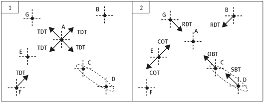
As noted before, nodes with ATB-DMAC scheme obtain the neighbor location information at the beginning of each packet transmission. Fig. 1 shows a comprehensive example that is set such that the application of each tone is considered. Suppose that in Fig. 1 (part 1) nodes A and F want to send data to nodes B and E, respectively. They start with TDT tone transmission on all M beams sequentially, to inform the neighbors about packet transmission and its own direction and also obtaining their neighbors’ location information. Fig. 1 (part 2) shows that nodes B and G are idle and sense no tone but TDT tone, therefore they reply with the RDT tone to inform about their presence and their availability on that beam. Nodes C and D are communicating with each other, thus reply with OBT (to prevent the deafness by informing about involving in a connection in another direction, getting OBT means that no collision has happened and receiver did not reply because it was involved in another direction thus back-off time increasing is not required.) and SBT (to prevent the hidden node problem by informing about involving in a connection in the same direction, which prevents any future interferences) tones, respectively. Node E senses TDT tone on two different beams and replies with COT tone to inform the transmitters about simultaneous TDT transmission and to prevent probable collision occurrence on this direction. Thereafter, node F receives the COT tone and goes to the TDT defer state, which is designed to prevent future simultaneous TDT transmissions. Node A only replies with RTS packets on the directions that RDT tones are received and does not send any signal to the directions which the OBT, SBT, and COT tones have been received. Based on the destination address in RTS packet, since the received RTS packet is not related to the node G, it does not reply. In response to the successful RTS reception, node B transmits the DDT tone (to inform about intended node location) and CTS packet. Since the transmitter does not scan packet antenna for CTS packet but instead scans out of band frequencies using tone antenna, the DDT tone transmission decreases the waiting time. When transmitter detects the DDT tone, selects the related packet beam. Finally, proper reception of data packet in receiver is acknowledged by ACK packet transmission. Due to node movements it is possible to have simultaneous RTS reception. The RCOT tone is designed to inform about any RTS collision occurrence.
3Performance analysis
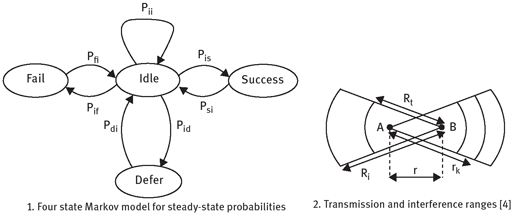
In [4], a three state discrete Markov model has been adopted for obtaining the saturation throughput. The proposed model in the current paper adopts the four state Markov model shown in Fig. 2 which has been used in [7] for performance evaluations. Based on this model saturation throughput and transmission delay can be calculated as follows:
where P(I), P(S), P(D), and P(F) are the steady-state probability of Idle, Success, Defer, and Fail states, and their duration has been denoted by Ti, Ts, Td, and Tf, respectively. TDATA denotes the average data packet duration. Note that non-idle nodes will return to idle state after the corresponding duration with probability 1. Thus, assuming Pxy as probability of transition from x to y, we have: Psi = Pdi = Pfi = 1. As depicted in Fig. 2 (part 1) each node is in one of the before-mentioned four states, which implies:
Using (3) and (4), we obtain P(I) = 1/(2 − Pii). Adopting Poisson distribution with density ρ for node locations over two dimensional plane, the probability of finding k nodes in an area of A is equal to:
Let us denote the transmission probability of each node with p, the probability of transition from idle state to itself can be expressed as equation (5). From Fig. 2 (part 1) we can see that the steady-state probability of different states and the idle state are related via equations P(S) = P(I)Pis, P(F) = P(I)Pif , and P(D) = P(I)Pid.
We define interference areas for different durations according to the depicted ranges in Fig. 2 (part 2), as below:
Let us denote the probability of successful reception in first time slot by P1 and in TDT, RDT, RTS-CTS-ACK, DDT, DATA durations by P2 to P6, respectively. Hence, we have:
In which TTone−Collision is the mean waiting time for tone transmission on each beam. Finally, we must obtain the idle, success, fail, and defer state durations. According to [5], we assume that Tf follows a truncated geometric distribution:
where TTDT and TRDT are time durations of TDT, RDT tones transmission, respectively. TRTS is time duration of RTS packet transmissions. The total RTS transmission time, can be derived as follows:
In which Pinp is the probability that at least one idle node presents in the transmission area A of intended node. For simplicity, we assume Ti = 1 and:
Given that channel is idle, the transmission probability of each node in the next time slot have been obtained in [6]. A transmission can be successful or not. Also, when a node receives a packet from higher layer and senses the channel busy or does not receive any data from physical/higher layer it will not transmit. Hence:
For evaluating the ATB-DMAC scheme using new model we conducted throughput and delay comparison with the RTS/CTS based DMAC scheme proposed in [5]. Since in RTS/CTS based DMAC, nodes transmit all packets directionally and do not inform neighbor nodes before packet transmission, we must substitute A0 with A3, and in P2 replace the TTone−Collision with TRTS. Also, T1 = TRTS +1, and T2 = TRTS + TCTS + TDATA + TACK +4.
4Numerical results
In order to evaluate the above schemes we set parameters as follows:
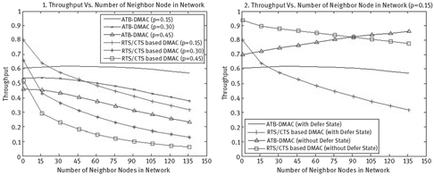
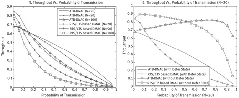
σ = 10, θ = n/8, TTDT = TRDT = TDDT =1, TRTS = 20, TACK = TCTS = 14 and TDATA = 1024. Fig. 3 (part 1) shows that when number of neighbor nodes is increased the ATB-DMAC outperforms the RTS/CTS based DMAC, e.g. in networks with p = 0.15, p = 0.30, and p = 0.45 for nodes with more than 20, 8, and 5 neighbor nodes, respectively. The results in Fig. 3 (part 2) show that, with four state Markov model, the ATB-DMAC scheme gives better throughput than the RTS/CTS based DMAC for wider range of network densities in comparison with the three state Markov model. Fig. 4 (part 3) shows that in a network with certain number of nodes the ATB-DMAC gives better performance for increasing in the probability of transmission. Also Fig. 4 (part 4) shows that based on the four and three state model throughput of nodes with 20 neighbor nodes that use the proposed scheme outperforms the RTS/CTS based scheme for 0.2 < p < 1 and 0.5 < p < 1, respectively, which means that the new scheme can outperform in wider range than that have been shown by the three state Markov model. Although, in part 2 and part 4 of Fig. 3 the three state model throughput is higher than that for the new model, but we shall notice that the defer state (also exponential back-off times [6] which has been considered in new model and can decrease the throughput severely) has not been considered in the previous model.
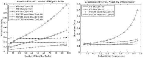
As shown in Fig. 5 (part 1) due to neighbor discovery duration, with low number of neighbor nodes the proposed scheme’s delay is higher than that for other scheme. For higher numbers, its delay increases slightly while it increases dramatically for latter scheme. Also, Fig. 5 (part 2) depicts that with same number of neighbor nodes for higher probability of transmission the proposed scheme’s delay is much better than that for the RTS/CTS based scheme.
5Conclusion
In this paper we reviewed the ATB-DMAC scheme which has been proposed for mitigation of the problems that are introduced in the MAC layer of the ad hoc networks due to the utilization of directional antennas. As this scheme uses some extra auxiliary tones for neighbor discovery at the beginning of data communications, a small decrease in throughput and a small increase in transmission delay for short data or low density networks are expected. The previously proposed three state Markov model showed that this scheme outperforms other schemes such as RTS/CTS based MAC scheme only in high density networks. In the current performance evaluation, we proposed a more realistic Markov model with four states in which also the defer state is considered. The comparison evaluations are performed for the ATB-MAC and the RTS/CTS based MAC schemes based on the new analytical model. Numerical results show that the proposed ATB-MAC scheme outperforms the RTS/CTS based MAC scheme not only in high density networks but also in networks with low probability of transmission and in low density networks. This reasonable performance of the ATB-DMAC scheme is obtained due to the satisfactory utilization of the auxiliary tones in preventing the occurrence of long time defer states which is a notable parameter in decreasing the throughput and forcing long delays.
Acknowledgment: The authors express their gratitude to the anonymous reviewers for their thorough reviews and constructive comments.
This work is dedicated to my late father Seyed Hassan Rahimi.
Bibliography
[1]R. R. Choudhury and N. H. Vaida. Deafness:AM AC problem in ad hoc networks when using directional antennas. Int. Conf. on network protocols (ICNP), :283–292, Berlin, Germany, October 2004.
[2]J. Deng and Z. J. Haas. Dual busy tone multiple access (DBTMA): Performance evaluation. IEEE Int. Veh. Technology Conf. (VTC), 1:314–319, Houston, TX, USA, May, 1999.
[3]C. S. Z. Huang, C.-C. Shen and C. Jaikaeo. A busy-tone based directional MAC protocol for ad hoc networks. Military Communications Conf., 2:1233–1238, Anaheim, CA, USA, October 2002.
[4]R. Rahimi, G. Dadashzadeh, M. Maleki and E.Jedari. An auxiliary tone based MAC scheme for high density ad hoc networks with directional antenna. 15th Asia-Pacific Conf. on Communications (APCC), Shanghai, China, October 2009.
[5]H. N. Dai, K. W. Ng, M. Y. Wu and B. Li. On collision-tolerant transmission with directional antennas. Wireless Communication and Networking Conf. (WCNC), :1968–1973, Las Vegas, NV, USA, Mar. 2008.
[6]G. Bianchi. Performance analysis of the IEEE 802.11 distributed coordination function. IEEE J. on Selected Areas in Communications, 18(3):535–547, Mar. 2000.
[7]H. Ma, H. M. K. Alazemi and S. Roy. A stochastic model for optimizing physical carrier sensing and spatial reuse in wireless ad hoc networks. IEEE Int. Conf. on Mobile ad-hoc and sensor systems (MASS’05), 8:615–622, Washington, DC, USA, Nov. 2005.
[8]J. Deng and Z.J. Haas. Dual busy tone multiple access (DBTMA): A new medium access control for packet radio networks. IEEE Int. Conf. on Universal Personal Communicationsthe (ICUPC), 2:973–977, Florence, Italy, October 1998.
[9]V. Shankarkumar, Y.B. Ko and N.H. Vaidya. Medium access control protocols using directional antennas in ad hoc networks. IEEE Computer and Communications Societies (INFOCOM), 1:13–21, Tel Aviv, Israel, March 2000.
[10]A. Nasipuri, S. Ye and R.E. Hiromoto. A MAC protocol for mobile ad hoc networks using directional antennas. IEEE Wireless Communications and Networking Conf. (WCNC), 3:1214–1219, Chicago, IL, USA, Sep. 2000.
[11]M. Takai, J. Martin, A. Ren and R. Bagrodia. Directional virtual carrier sensing for directional antennas in mobile ad hoc networks. 3rd ACM Int. Symp. on Mobile Ad Hoc Networking and Computing, : 183–193, Lausanne, Switzerland, June 2002.
[12]R. R. Choudhury, X. Yang, R. Ramanthan and N. H. Vaidya. Using directional antennas for medium access control in ad hoc networks. Int. Conf. on Mobile Computing and Networking (MobiCom), pp. 59-70, Atlanta, GA, USA, September 2002.
[13]T. Korakis, G. Jakllari and L.Tassiulas. A MAC protocol for full exploitation of directional Antenna in ad-hoc wireless networks. 4th ACM Int. Symp. on Mobile Ad Hoc Networking and Computing, :98–107, Annapolis, MD, USA, June 2003.
[14]H. Singh and S. Singh. Smart-802.11b MAC protocol for use with smart antennas. IEEE Int. Conf. on Communication (ICC2004), 6:3684–3688, Paris, France, June 2004.
[15]R. Ramanthan. On the performance of ad hoc networks with beamforming antennas. 2nd ACM Int. Symp. on Mobile Ad Hoc Networking and Computing, :95–105, Long Beach, CA, USA, October 2001.
[16]N. S. Fahmi, T. D. Todd and V. Kezys. Ad hoc networks with smart antennas using IEEE 802.11-based protocol. IEEE Int. Conf. on Communication (ICC2002), 5:3144–3148, Newyork, NY, USA, 2002.
[17]L. Bao, J.J. Garcia-Luna-Aceves. Transmission scheduling in ad hoc networks with directional antennas. Int. Conf. on Mobile Computing and Networking (MobiCom), :48–58, Atlanta, GA, USA, September 2002.
[18]J. P. Monks, V. Bhargavan and W. W. Hwu. A power controlled multiple access protocol for wireless packet networks. IEEE Computer and Communication Societies (INFOCOM), 1:219–228, Anchorage, AK, USA, April 2001.
[19]S-L Wu, Y-C Tseng and J-P Sheu. Intelligent medium access for mobile ad hoc networks with busy tones power control. Int. Conf. of Computer Communications and Networking, :71–76, Boston, MA, USA, October 1999.
Biographies

Razgar Rahimi was born in Saghez, Kurdistan, Iran in 1981. He received the B.Sc. degree in electrical engineering from Iran University of Science and Technology, Tehran, Iran in 2005, and the M.Sc. degree in electrical engineering from Shahed University, Tehran, Iran in 2010. His recent research interests include cognitive radio networks and cooperative communication systems.

Gholamreza Dadashzadeh was born in Urmia, Iran, in 1964. He received the B.Sc. degree in communication engineering from Shiraz University, Shiraz, Iran, in 1992 and M.Sc. and Ph.D. degrees in communication engineering from Tarbiat Modarres University, Tehran, Iran, in 1996 and 2002, respectively. From 1998 to 2003, he has worked as the Head Researcher of the Smart Antenna for Mobile Communication Systems and the wireless local-area network 802.11 project with the radio communications group of Iran Telecommunication Research Center (ITRC). From 2004 to 2008, he was the Dean of the Communications Technology Institute, ITRC. He is currently an Assistant Professor with the Electrical and Electronic Engineering Department, Shahed University, Tehran. He has published more than 80 papers in referred journals and international conferences in the area of antenna design and smart antennas. Dr. Dadashzadeh is a member of the Institute of Electronics, Information, and Communication Engineers of Japan and the Iranian Association of Electrical and Electronics Engineers. He received the first degree of national researcher in 2007 from Iran’s Ministry of Information and Communications Technology.