Input Devices
An input device is one that transfers information from outside the computer system to an internal storage location, such as system RAM, video RAM, flash memory, or disk storage. Without input devices, computers would be unable to change from their default boot-up state. The following sections detail different classes of input devices and a hub, of sorts, used for switching between the most common of these devices. We will also demonstrate the similarities shared by devices that provide input to computer systems as well as their differences. Installation considerations will be presented where appropriate. The following input devices are covered in the following sections:
- Mouse
- Keyboard
- Barcode reader
- Multimedia devices
- Biometric devices
- Touchscreen
- KVM switch
- Scanner
- Gamepads and joysticks
- Digitizer
Mouse
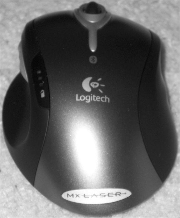
Although the computer mouse was born in the 1970s at Xerox’s Palo Alto Research Center (PARC), it was Apple in 1984 that made the mouse an integral part of the personal computer image with the introduction of the Macintosh. In its most basic form, the mouse is a hand-fitting device that uses some form of motion-detection mechanism to translate its own physical two-dimensional movement into onscreen cursor motion. Many variations of the mouse exist, including trackballs, tablets, touchpads, and pointing sticks. Figure 3-44 illustrates the most recognizable form of the mouse.
Figure 3-44: A computer mouse
The motion-detection mechanism of the original Apple mouse was a simple ball that protruded from the bottom of the device so that when the bottom was placed against a flat surface that offered a slight amount of friction, the mouse would glide over the surface but the ball would roll, actuating two rollers that mapped the linear movement to a Cartesian plane and transmitted the results to the software interface. This method of motion detection remains available today, although it’s fairly unpopular.
Later technologies used optical receptors to catch LED light reflected from specially made surfaces purchased with the devices and used like a mouse pad. A mouse pad is a special surface to improve mechanical mouse traction while offering very little resistance to the mouse itself. As optical science advanced for the mouse, lasers were used to allow a sharper image to be captured by the mouse and more sensitivity in motion detection. Certain surfaces don’t lend themselves well to standard laser-mouse functionality, but a higher resolution version exists that can even track across the surface of glass. The mouse today can be wired to the computer system or connected wirelessly. Wireless versions use batteries to power them, and the optical varieties deplete these batteries more quickly than their mechanical counterparts.
The final topic is one that is relevant for any mouse: buttons. The number of buttons you need your mouse to have is dependent on the software interfaces you use. For the Macintosh, one button has always been sufficient, but for a Windows-based computer, at least two are recommended, hence the term right-click. Today, the mouse is commonly found to have a wheel on top to aid in scrolling and other specialty movement. The wheel has even developed a click in many models, sort of an additional button underneath the wheel. Buttons on the side of the mouse that can be programmed for whatever the user desires are more common today as well and can alarm the unsuspecting user the first time they grab such a mouse the wrong way.
Touch pads—flat panels below the spacebar—and pointing sticks—eraser-like protrusions in the middle of the keyboard—are found mainly on laptops. A trackball, however, is more like an inverted mouse, so let’s look at how they compare to each other. Both devices place the buttons on the top, which is where your fingers will be. A mouse places its tracking mechanism on the bottom, requiring that you move the entire assembly as an analogue for how you want the cursor on the screen to move. In contrast, a trackball places the tracking mechanism, usually a ball that is larger than that of a mouse, on the top with the buttons. In doing so, you have a device that need not be moved around on the desktop and can work in tight spaces and on surfaces that would be incompatible with the use of a mouse. The better trackballs place the ball and buttons in such a configuration that your hand rests ergonomically on the device, allowing effortless control of the onscreen cursor.
Keyboard
More ubiquitous than the mouse, the keyboard is easily the most popular input device, so much so that its popularity is more of a necessity. Very few users would even think of beginning a computing session without a working keyboard. Fewer still would even know how. The US English keyboard places keys in the same orientation as the QWERTY typewriter keyboards, which were developed in the 1860s.
In addition to the standard QWERTY layout, modern computer keyboards often have separate cursor-movement and numerical keypads. The numerical keys in a row above the alphabet keys send different scan codes to the computer from those sent by the numerical keypad. At the discretion of the programmer, any given application might require the use of only one of the two sets of numeric keys or allow the use of either. The IBM PC/AT keyboard had only 84 keys, lacking separate cursor-movement keys. These functions were superimposed on the numeric keypad only. The Num Lock key had to be toggled to switch between cursor movement and the numeric keypad. The 101-key keyboard did include these separate keys but still kept the Num Lock arrangement as well, and the popular 104-key Windows keyboard added Windows-specific keys to those 101 keys.
Keyboards have also added function keys (not to be confused with the common laptop key labeled Fn), which are often placed in a row across the top of the keyboard above the numerical row. Key functionality can be modified by using one or more combinations of the Ctrl, Alt, Shift, and laptop Fn keys along with the normal QWERTY keys.
Technically speaking, the keys on a keyboard complete individual circuits when each one is pressed. The completion of each circuit leads to a unique scan code that is sent to the keyboard connector on the computer system. The computer uses a keyboard controller chip or function to interpret the code as the corresponding key sequence. The computer then decides what action to take based on the key sequence and what it means to the computer and the active application, including simply displaying the character printed on the key.
In addition to the layout for a standard keyboard, other keyboard layouts exist, some not nearly as popular, however. For example, without changing the order of the keys, an ergonomic keyboard is designed to feel more comfortable to users as they type. To accomplish that goal, manufacturers split the keyboard down the middle, angling keys on each side downward from the center.
The Dvorak Simplified Keyboard, patented in 1936, was designed to reduce fatigue in the hands of typists by placing characters that are more commonly used in the home row, among other physiologic enhancements. The QWERTY layout was designed to keep the hammers of a typewriter from becoming entangled. Although the Dvorak keyboard makes logical sense, especially with the decline in manufacturing and sales of the classic typewriter, the QWERTY keyboard remains dominant. One reason the Dvorak keyboard has failed to take over might be the loss of productivity to a touch-typist as they retrain on the new format.
Scanner
One of the earliest input devices aside from the keyboard and mouse was the scanner. Before USB, scanners would routinely connect to computers through a SCSI bus, alongside external drives. Many models supported parallel attachment in the place of a printer, which was helpful for simpler systems with no SCSI interfaces; almost all computers had parallel ports in those days. Look for a menu item in applications capable of scanning that specifies TWAIN, the generic term for the class of drivers associated with scanners, such as Select TWAIN Source. This selection allows you to choose among multiple scanners before initiating the scan job.
More affordable scanners were handheld devices that relied on included or specialty software to intelligently stitch together the scanned ribbons into one cohesive image. Although more easily afforded today, flatbed scanners were once reserved for the computing elite. Regardless of the caliber of scanner, they all use light to reflect off of a surface and measure the relative reflections of the different dots that make up the grid the scanner is able to detect. The tighter the grid (the more dots per inch [DPI] supported), the higher resolution the resulting image. Charge coupled devices (CCDs) are a common choice in today’s scanners. CCDs convert light they receive into electrical impulses that is then forwarded to the software producing the scan for further processing into an image that is a facsimile of the original object being scanned.
A flatbed scanner evokes the concept of a copier with the paper handling and printing mechanisms missing. This image is not far off, which is why copiers make wonderful scanners, as long as they can produce a digital image file. It’s also why multifunction devices are so prolific; it takes very little to outfit a printer with a scanner component to be used for input to the computer and as a fax-scanning device. Inbound faxes can be printed, or the same digital interface that the scanner uses can be used to transfer the image electronically to software in the computer. Figure 3-45 shows the top flatbed scanner portion of a laser multifunction device that provides a way to print, scan, and fax.
Figure 3-45: A flatbed scanner
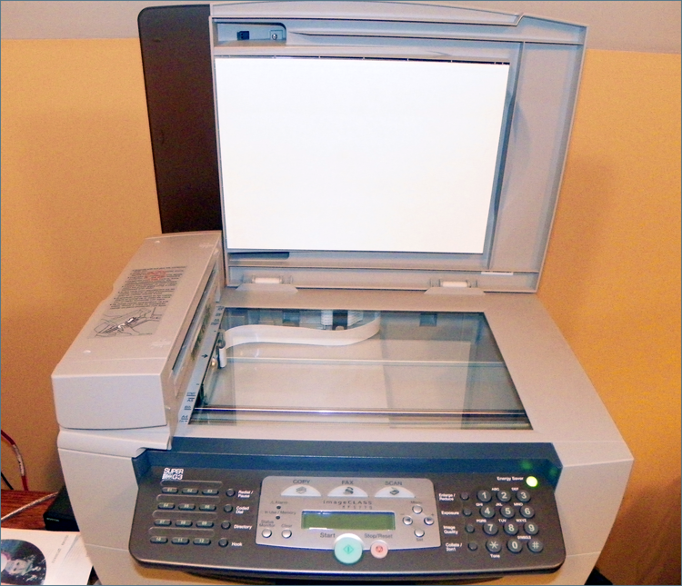
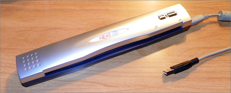
Figure 3-46 shows you one of numerous brands of portable document scanners. These handy little devices are scarcely more than a foot long and can make short work of scanning anything from a business card to a gas receipt to an 8.5″ × 11″ lodging folio. The associated software that comes with these scanners performs optical character recognition (OCR) and can recognize the orientation of the text and glean pertinent information from the documents scanned to populate the internal database. From this database, you can produce reports for such purposes as expenses, invoicing, and taxes. This model also offers the option to create a PDF during the scan instead.
Figure 3-46: A portable document scanner
Barcode Reader
A barcode reader (or barcode scanner) is a specialized input device commonly used in retail and other industrial sectors that manage inventory. The systems that the reader connects to can be so specialized that they have no other input device. Barcode readers can use LEDs or lasers as light sources and can scan one- or two-dimensional barcodes.
Barcode readers can connect to the host system in a number of ways, but serial connections, such as RS-232 and USB, are fairly common. If the system uses proprietary software to receive the reader’s input, the connection between the two might be proprietary as well. The simplest software interfaces call for the reader to be plugged into the keyboard’s PS/2 connector using a splitter, or “wedge,” that allows the keyboard to remain connected. The scanner converts all output to keyboard scans so that the system treats the input as if it came from a keyboard. For certain readers, wireless communication with the host is also possible, using IR, RF, Bluetooth, WiFi, and more.
With today’s smartphone technology being what it is, the built-in cameras can act as scanners, and the scanning app can interpret what the camera sees. In this way, Universal Product Code (UPC) barcodes and Quick Response (QR) codes and other 2D matrix barcodes can be input and processed. The smartphone can then use its Internet access to launch the application associated with the text, such as a web browser or an email client. A QR code is an encoded image that allows the scanning application to decode large amounts of text and can be used to represent simple text or popular strings, such as a website’s URL, a phone number, a GEO location, an email address, or an SMS message. Figure 3-47 is a simple QR code that will direct a QR-code reader app to the www.sybex.com website.
Figure 3-47: A QR code
Digitizer
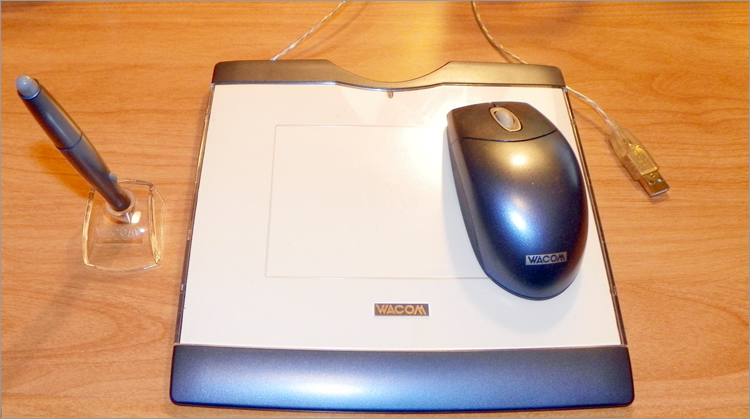
One way to faithfully reproduce incredibly good artwork in digital form for computer use is to place the analog artwork on top of a sensor and use a stylus to trace the artwork after choosing an onscreen “crayon” or “pen.” The end result can be a work of art almost as good as the original. The device used to trace an analog source, turning it into a digital representation, is a digitizer. Digitizing, in fact, is the act of turning any analog source—artwork, audio, video, slides and photographs—into a binary bit stream. As an input device, however, a digitizer or digitizing tablet takes pen strokes in the analog world and turns them into a digital rendering through the software controlling the digitizer. These devices are also commonly used to annotate presentations with the option to save or discard the annotations with each presentation. Figure 3-48 shows an example of a USB-attached digitizing tablet with choice of pen or mouse for input.
Figure 3-48: A digitizing tablet
Biometric Devices
Any device that measures one or more physical or behavioral features of an organism is considered a biometric device, or literally, a device that measures life. When the same device forwards this biometric information to the computer, it becomes an input device. The list includes fingerprint scanners, retinal and iris scanners, voice recognition devices, and facial recognition devices, to name a few. A computer can use this input to authenticate the user based on preestablished biometric information captured during user setup. Even cipher locks that authenticate personnel before allowing entry to secure environments can be replaced with biometric devices.
Because there are many manufacturers of biometric devices, the installation of any particular model is best performed while consulting that company’s documentation. If the device is not built into the computer, at a minimum some form of interface, such as USB, must be used to attach the device, and software must be installed to lock the system until authentication occurs. Many offerings allow multiple forms of authentication to be required in sequence. An example of a highly secure approach to authentication with multiple factors would be a biometric scan, followed by a challenge that requires a code from a token card, followed finally by the opportunity to enter a password. This “something you are, something you have, and something you know” technique works to secure some of the world’s most sensitive installations. Further discussion of the concept of multifactor authentication is beyond the scope of this book.
Touchscreens
Touchscreen technology converts stimuli of some sort, which are generated by actually touching the screen, to electrical impulses that travel over serial connections to the computer system. These input signals allow for the replacement of the mouse, simultaneously in movement and in click. With onscreen keyboards, the external keyboard can be retired as well. However, standard computer systems are not the only application for touchscreen enhancement. This technology can also be seen in PDAs and smartphones, point-of-sale venues for such things as PIN entry and signature capture, handheld and bar-mounted games, ATMs, remote controls, appliances, and vehicles. The list continues to grow as technology advances.
For touchscreens, a handful of solutions exist for converting a touch to a signal. Some less-successful ones rely on warm hands, sound waves, or dust-free screens. The more successful screens have optical or electrical sensors that are quite a bit less fastidious. The two most popular with handheld devices are resistive and capacitive. Capacitive interfaces are generally smoother to the touch than resistive interfaces and can be controlled by the pad of the finger or a special stylus that mimics this soft part of the fingertip. Resistive interfaces usually have to be controlled by the fingernail or a plastic or metal stylus. In any event, the sensory system is added onto a standard monitor at some point, whether in the field by the user or in a more seamless fashion by the manufacturer.
Installing monitors with touch capability on standard computers entails not only attachment to the graphics adapter, but also attachment to a serial interface. The most popular of these has become the USB port, much as it has for the mouse and keyboard.
Calibration is required upon first configuration and whenever there appears to be a misinterpretation by the system as to where the user has touched the screen. This calibration entails displaying a pattern that the user has to touch at certain points to let the system know where these landmarks are perceived to be.
KVM Switch
A KVM switch isn’t an input device, but it allows you to switch between sets of input devices. The KVM switch is named after the devices among which it allows you to switch. The initials stand for keyboard, video, and mouse. KVM switches come in a variety of models. You can select the switch that accommodates the type of interfaces your components require. For example, your keyboard and mouse might attach with mini-DIN connectors or with USB connectors; your monitor might attach with a VGA, DVI, or HDMI connector.
The purpose of the switch is to allow you to have multiple systems attached to the same keyboard, monitor, and mouse. You can use these three devices with only one system at a time. Some switches have a dial that you turn to select which system attaches to the components, while others feature buttons for each system connected. Common uses of KVM switches include using the same components alternately for a desktop computer and a laptop docking station or having a server room with multiple servers but no need to interface with them simultaneously.
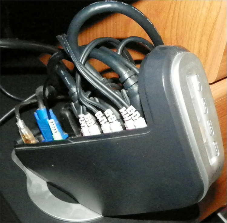
Figure 3-49 shows a four-system VGA/USB switch with analog audio switching as well. If DVI or PS/2 attachments are desired, for example, adapters are required. The buttons on the front (right side of the image) switch the common console connections (on the left side of the image) among the four systems, only three of which are currently attached. A maximum of one of the four LEDs beside the corresponding buttons is lit at a time, only for the system currently in control.
Figure 3-49: A KVM switch
Gamepads and Joysticks
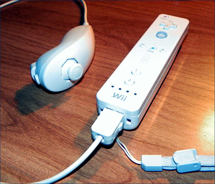
As long as there have been gaming applications for the personal computer, there have been standard and specialty controllers for some of those games. For the rest, the keyboard and mouse could be or had to be used for controlling the game. Two popular types of controllers have been the generic joystick, a controller with one or more buttons and a stick of varying length and girth, and the often proprietary gamepad, usually comprising function and directional buttons specific to the gaming console in use. Standardized PC connections have included the DA15 game port, also known as the joystick port, the DB25/DE9 serial port, and the USB port. Figure 3-50 shows a wired joystick connected through the wireless controller for the Nintendo Wii video game console.
Figure 3-50: A proprietary gamepad