Chapter 4
Radiation of a Printed Antenna 1
4.1. Introduction
Our analysis of the radiation of a rectangular patch antenna will be based on the cavity model from Chapter 3. Using two equivalent radiating apertures, we will derive expressions for the radiated field and directivity. A parametric study of the influence of various characteristics (substrate height and permittivity, antenna width, and truncation of the ground plane) will also take place.
The equivalent sources of the problem are the virtual magnetic currents which result from Huygens’ principle, with the associated concept of a radiating aperture. This approach is similar to that of the horn antennas, where knowing the electric field (or equivalent magnetic current) distribution in the aperture enables the radiation to be determined more easily than as a result of the distribution of the electric current on the metallic sides.
Note that the real sources are the electric currents and charges present in the metallic parts of the antenna. They constitute the unknown factors to be determined for a number of commercial software applications used in planar antenna design (such as IE3D or Ansoft Designer). This explains why nowadays engineers gain their understanding of the workings of an antenna from electrical current cartographies rather than 3D electrical field distributions, i.e. from magnetic currents.
However, the physical approach to radiation through the radiating aperture concept is often more pertinent than that of the distribution of electrical sources which make up the patch. Indeed, the ground plane close to the patch fundamentally constitutes an electrical short circuit which, according to image theory, is little suited to the radiation of horizontal electrical currents. This obstacle is overcome by using the radiating aperture concept.
4.2. Modelization using two equivalent radiating slots
According to Huygens’ principle, any closed surface which contains electromagnetic sources can be used in order to calculate the field that they radiate. The key is to determine the tangential E and H fields on this surface, or else the equivalent magnetic M and electrical J surface currents, which create the same radiated field as the sources. These fields or currents must satisfy the boundary conditions on the surface and become new sources of radiation, also called secondary sources. A judicious choice of surface can considerably simplify the calculation of the radiated field from secondary sources. In case of the rectangular patch antenna, the closed cavity formed from the lateral magnetic walls, the surface of the patch and the surface next to the ground plane will form the Huygens surface.
Let us apply image theory to replace the patch and the supposedly infinite ground plane with the patch and its image (Figure 4.1). On the one hand, the electrical surface current of the patch and the image of this current are running in opposite directions. On the other hand, the gap between these two currents is very small compared with the wavelength, as h≪λ. The radiation of the two currents will therefore tend to cancel out, which justifies not taking the upper metallic surface of the cavity into account in the calculations. Note that this reasoning implicitly links the contributions of the currents which exist on the ground plane. In other words, the lower metallic surface of the equivalent cavity is also ignored in the calculation of the radiated field.
Figure 4.1. Image theory applied to horizontal electrical currents

In order to determine the E field on the vertical lateral surfaces, we will base our reasoning on the TM10 mode, the distribution for which is shown again in Figure 4.2. Along the so-called radiating edges with a width W, only the vertical component of the electrical field exists, uniformly distributed over the surface. Since the edges are a half guided wavelength apart, fields E1 and E2 on each aperture are of the same amplitude and in phase opposition. On the edges with a length L, which are said to be non-radiating, we observe a phase reversal of the purely vertical electrical field at the center of the surface.
Figure 4.2. Distribution of magnetic current on radiating and non-radiating slots for the TM10 mode

The surfaces of the radiating edges can be seen as radiating apertures (or slots) and can be replaced by an equivalent distribution of surface current. This current does not contain any electrical component ![]() , the H field tangential component being null on the apertures. Let
, the H field tangential component being null on the apertures. Let ![]() and
and ![]() be the normals to the apertures oriented toward the exterior of the cavity (Figure 4.2). The surface distributions of magnetic current
be the normals to the apertures oriented toward the exterior of the cavity (Figure 4.2). The surface distributions of magnetic current ![]() over the two apertures are given by:
over the two apertures are given by:
[4.1] ![]()
[4.2] ![]()
With the normals and fields being in opposite directions in each aperture, the magnetic currents MS1 and MS2 are oriented in the same direction. As h << λ and E is constant over the aperture, we can assimilate the surface current MS to a linear current M in each aperture, the intensity for which is given by:
[4.3] ![]()
Applying the image principle, the ground plane is replaced by the image of the magnetic current, which is oriented in the same direction as the real current (Figure 4.3). Under the hypothesis h << λ, we can therefore combine the equivalent magnetic source of an aperture and its image into one single source of intensity 2V0.
Figure 4.3. Image theory applied to horizontal magnetic currents

The linear currents in each aperture, M1 and M2, are finally given by:
[4.4] ![]()
It is convenient to replace these linear magnetic currents ![]() and
and ![]() with horizontal radiating apertures of the same dimensions as the vertical apertures described in Figure 4.4. Once again, this is only valid when h << λ (in practice, h < λ/50).
with horizontal radiating apertures of the same dimensions as the vertical apertures described in Figure 4.4. Once again, this is only valid when h << λ (in practice, h < λ/50).
Figure 4.4. Modelization using two horizontal radiating slots
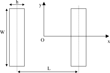
The idea is then to utilize the theory of radiating apertures in order to calculate the components of the field radiated by a slot, and then to combine the radiation of the two slots in order to obtain the radiation of the patch.
The same reasoning enables us to trace the linear magnetic currents over the nonradiating edges of the patch (Figure 4.2). We observe an inversion of the direction of magnetic current at each edge, as well as a phase opposition between the currents of opposing edges. These currents therefore lead to null radiation in the principal planes xOz and yOz.
Conversely, there is non-null radiation away from the axis in the other planes; however, the density of this is much weaker than that of the radiating edges.
In conclusion, it is possible to determine the field radiated by the rectangular patch by combining the radiation of two equivalent radiating slots which are positioned along the two edges with width W.
4.3. Calculation of the field radiated by a horizontal radiating slot
The field radiated by an aperture of length W and width h, in which a uniform field ![]() exists, is given by [BAL 05, CAR 81]:
exists, is given by [BAL 05, CAR 81]:
[4.5] ![]()
[4.6] ![]()
[4.7] ![]()
[4.8] ![]()
[4.9] ![]()
We note that when h<<λ, then:
[4.10] ![]()
[4.11] ![]()
4.4. Calculation of the field radiated by the rectangular patch
Let us now consider the mini-array comprising two slots, a distance of L apart, aligned along axis Ox, and let us take the center of the patch as the origin. Under these conditions, we know that the array factor AF of the two elements which are a distance of L apart is given by:
[4.12] ![]()
Using array theory, the total field is calculated by multiplying the field of an elementary source of the array by AF. The field radiated by the two equivalent slots is therefore given by:
[4.13] ![]()
[4.14] ![]()
4.5. Determination of the radiation pattern in the principal planes
![]()
This plane is called the E-plane as it oriented the same way as the electrical field in the equivalent apertures. Setting φ = 0° in expressions [4.13] and [4.14], we obtain:
[4.15] ![]()
[4.16] ![]()
The radiation pattern depends solely on L. For the first resonance, omitting the virtual extensions ΔL, we have:
[4.17] ![]()
from which:
[4.18] ![]()
and:
[4.19] 
Figure 4.5. Influence of the effective permittivity on the E-plane radiation pattern ![]()
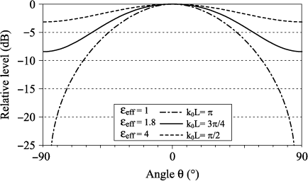
In Figure 4.5, we vary the value of εeff between 1 and 4. We see a radiation pattern which widens with increases in εeff and which does not cancel out for low grazing angles. The distance between the radiating slots is reduced at higher levels of permittivity and the array effect is less pronounced.
For higher levels of permittivity, the radiation pattern moves closer to that of a unique slot, i.e. it is uniform in the E-plane.
![]()
This plane is orthogonal to the E-plane. Expressions [4.13] and [4.14] reduce to:
[4.20] ![]()
[4.21] ![]()
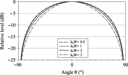
The radiation pattern depends on W throughout the function sinX/X. This dependency results in a widening of the H-plane radiation pattern for reduced values of W (Figure 4.6), which is consistent with radiating aperture theory.
We note that the H-plane radiation pattern is always narrower than the E-plane pattern and that the field cancels out for angles close to horizontal. In the particular instance where the permittivity is close to that of air, the aperture is roughly the same in both planes.
Figure 4.6. Influence of the width W on the H-plane radiation pattern
4.6. Influence of height
Initially, we ignored the influence of h on the radiation pattern in the hypothesis where h << λ, since the product:
[4.22] ![]()
which is common to equations [4.5] and [4.6], tends toward 1.
We note that K is a function which, for a given value of h, increases with θ between cos(k0h) and 1, the value of cos(k0h) reducing in the same proportion as h increases. In other words, the radiation pattern will become narrower as h increases, so long as h remains small enough for approximations to remain valid.
Physically, this increase in h corresponds to field lines which are more open at the extremities, wider equivalent apertures and therefore to a narrower radiation pattern based on aperture theory.
4.7. Influence of the ground plane
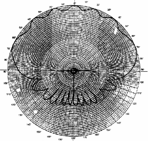
In practice, the ground plane and the substrate are necessarily truncated. The finite nature of the lateral dimensions results in a diffraction of the space and surface waves over the ridges of the ground plane. This diffraction leads to parasitic radiation toward the front and back of the antenna.
The front-to-back radiation ratio is typically less than −20 dB for dimensions of the ground plane greater than two wavelengths and for a centered patch. The parasitic radiation toward the front of the antenna generates ripples in the principal radiation pattern (Figure 4.7).
Figure 4.7. Influence of the ground plane on the E-plane radiation
4.8. Polarization
A rectangular patch antenna which is excited along bisector Ox presents a linear polarization of the radiated electrical field. Indeed, we observe in equations [4.13] and [4.14] that field components Eθ and Eφ are in phase opposition, which is sufficient to produce a purely linear polarization in all directions. The Cartesian coordinates are easily deduced from equations [4.13] and [4.14]:
[4.23] ![]()
[4.24] ![]()
[4.25] ![]()
Note that component Ey is not present when TM10 is the only excited mode. Component Ez cancels out in the H-plane (φ = 90°) and at the antenna axis (θ = 0°). ![]() is therefore parallel to the field in the radiating apertures for the maximum direction of radiation.
is therefore parallel to the field in the radiating apertures for the maximum direction of radiation.
The purity of polarization depends on the amount of power transmitted in the unwanted cross-polarization Ey. The level of purity is characterized by the crosspolarization ratio τp:
[4.26] ![]()
The presence of cross-polarization will lead to a mismatch in the polarization between the transmitting and receiving antennas to the detriment of the link budget, but this is not the main consequence.
Let us consider an RF link where the channels are spread between two orthogonal linear polarizations (which are typically called V and H) for a common frequency band.
The diplexing (or filtering) between two orthogonal channels centered over the same frequency depends on the quality of the purity of polarization; the crosspolarization for the V channel constitutes an interference signal for the H channel, and vice versa.
Ratios less than −40 dB are generally required, which are difficult levels for patch antennas to meet, even if setting them into an array improves the purity of polarization of the simple element.
Cross-polarization can result:
– from the contribution of the non-radiating apertures. We have seen that this contribution is weak, notably at the axis of the TM10 mode;
– from the excitation of modes which are either orthogonal (TM01 and TM02) or which possess an orthogonal component (TM11). This excitation occurs under certain conditions:
- excitation of the TM01 mode: in order to excite this mode, the feed must be off-center relative to the bisector Ox. The cross-polarization then increases in proportion to the proximity of the matching point of the TM01 mode on the bisector Oy and when the resonant frequencies of the TM10 and TM01 modes are close. In case of limited excitation over the diagonal and of a square patch, the two modes are excited with the same intensity and τp = 0 dB,
- excitation of the TM02 mode: since the maximum of the TM02 mode is on the bisector Ox, it can be excited at the same time as the TM10 mode, if the resonant frequencies of the two modes are close. This is only possible when the width W is close to double the length L,
- from the influence of a feed circuit: the feed circuit possesses a parasitic radiation which contributes to cross-polarization. It also locally modifies the fields in the antenna. The resulting interference can be modelized by a superposition of higher modes, with each contributing to the cross-polarization according to its weighting.
4.9. Directivity
The directivity D of an antenna radiating a total power Pr, for a given distance r, is expressed as the ratio between:
– the surface density of power radiated by the antenna in the same direction as its maximum radiation:
[4.27] ![]()
– the surface density of power radiated by an isotropic antenna radiating the same total power Pr as the considered antenna:
[4.28] ![]()
and finally:
[4.29] ![]()
According to equations [4.15] and [4.16], it appears that the maximum amplitude of the field obtained for θ = 0 is:
[4.30] ![]()
The power radiated by a slot with conductance G is GV02 /2. In order to determine the total power radiated by the printed antenna Pr, we need to add together the power radiated by each of the two equivalent slots:
[4.31] ![]()
and, by using [2.10] and [2.11], we conclude that:
[4.32] 
and:
[4.33] 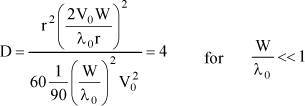
i.e. D (dB) = 6 dB. The formulae are valid under the hypothesis where the mutual conductance G12 between radiating slots is negligible compared with G. If this is not the case, then the directivity can be re-written as:
[4.34] 
However, the approximations necessary for the analytical determination of the conductance G of the slot (W << λ0 or W >> λ0) limit the usefulness of formulae [4.32] and [4.33].
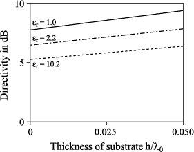
Figure 4.8 shows the theoretical results highlighting the influence of substrate thickness for several values of relative permittivity. With the effective area of the antenna increasing when its electrical volume increases, the directivity is much higher when the thickness is significant and the permittivity is weaker.
Figure 4.8. Influence of substrate thickness on directivity
4.10. Influence of the substrate on resonant frequency: parametric study based on antenna RCS
The objective is to analyze the influence of the substrate on variations in resonant frequency of a printed antenna. This study is carried out by calculating the equivalent radar area of the antenna. The RCS (Radar Cross Section), which is expressed in m2, characterizes the capacity of the target to reflect electromagnetic energy toward the transmitter which illuminates it. It is the expression of a relationship between the re-emitted energy and the density of energy received per unit area.
Since the RCS of a printed antenna is at its maximum when the antenna functions at its resonant frequency fr, we can determine the value of fr with commercial software using the following steps:
– for a given substrate thickness and dielectric constant, illumination of the antenna by a plane wave at normal incidence, the component of incident field E corresponds to the polarization of the antenna;
– determination of the field reflected by the antenna in the normal direction;
– calculation of the ratio of the reflected field over the incident field;
– analysis in a frequential band and determination of the frequency at which the RCS is at its maximum.
This method has a double relevance:
– when the thickness of the antenna increases and the resonances are less pronounced, the equivalent RLC model becomes less pertinent and the definition of the resonance is no longer clearly linked to the input impedance Za of the antenna (via a maximum value of Re(Za) or Im(Za) = 0) or to its minimum reflection coefficient;
– the influence of the feed circuit which modifies the structure of the antenna is released from fr. We also avoid readjusting the antenna at the impedance of the input port when the substrate’s characteristics are modified. Let us take the example of an antenna comprising a 4-mm square patch. In Figure 4.9, we observe a linear decrease in resonant frequency according to substrate thickness.
Figure 4.9. Influence of substrate thickness on frequency fr for εr = 2 and εr = 10
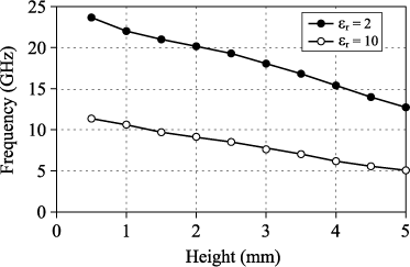
Figure 4.10. Influence of relative permittivity εr on resonant frequency for two substrate thicknesses, h = 0.254 and 2.254 mm
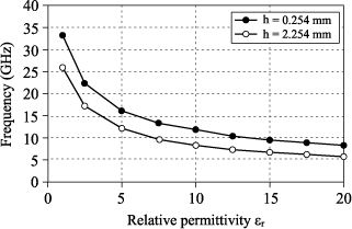
The transmission line model and the concept of the virtual extension ΔL given in equation [2.3] enable us to confirm this dependency, with ΔL showing a first-order increase based on substrate thickness h. In Figure 4.10, we confirm a ![]() decrease. This is in accordance with equation [2.2], the resonant length of the antenna being close to
decrease. This is in accordance with equation [2.2], the resonant length of the antenna being close to ![]() where εeff is of the order of εr.
where εeff is of the order of εr.
1 Chapter written by Jean-Marc LAHEURTE.
