
Chapter 9
Miniature Antennas 1
9.1. Introduction
The surge in new technologies is enabling more and more features for compact mobile terminals to be presented. Numerous wireless communication standards are being developed, some concurrent, some complementary. For example, it is well known that standards in mobile telephony present a wide coverage and allow a high mobility, while standards in wireless local area networks, such as the IEEE 802.11 standards, enable much higher throughputs, but with poorer coverage and more reduced mobility. A terminal claiming to offer a large range of services with variable throughputs and dynamics should therefore integrate send/receive modules working with several intrinsically different characteristic standards. A common characteristic will, in the case of mobile terminals, always be bulk: with user acceptance assuming a practical and aesthetically pleasing object, then, this being the case, antennas must be as discreet as possible.
Furthermore, each communication standard has been allocated a band of defined working frequencies by the regulatory authorities. As we will see later, the width of the allocated spectrum will directly influence the bandwidth of the antenna and therefore its size. The standards also induce particular characteristics in the performance of the antenna, such as its matching level, the form of radiation created, field polarization, or even a multiplication of the number of antennas for the same standard, as is the case in multiple input, multiple output (MIMO) technologies.
We are going to look at the design principles for small-sized antennas, their physical limitations, the compromises to be found, as well as the most used structures of compact antennas with their advantages and disadvantages. We will also discuss possible strategies for conforming these antennas and integrating different operating modes into one structure.
9.2. Which types of antennas should be used for integration?
Among the numerous families of antennas, not all are appropriate in the context of highly integrated structures where the antennas must be most compact. In summary, we can consider two principal families of antennas: non-resonant and resonant.
9.2.1. Non-resonant antennas
At the heart of the grand family of non-resonant antennas we find two subgroups: very small size of the antenna (compared to wavelength) and those that are relatively large in terms of wavelength. We must a priori eliminate very large antennas (traveling wave antennas, which we would assume to have at least one very significant dimension) that are not intrinsically matched to applications requiring low profile. Nevertheless, some antennas can be used in ultra-wideband (UWB) applications, but this particular case is dealt with in Chapter 8.
Antennas with very small sizes (compared to wavelength) appear attractive where strong integration is needed. This is the case, for example, with magnetic loops (very small loop conductor wire elements) or non-resonant dipoles (small wired elements that are symmetrical in open circuit). These antennas are used when the wavelength is so large that no resonant system can be envisaged. If we take, for example, a 125 kHz radio-frequency identification (RFID) reader, this has a wavelength of 2,400 meters and, indeed, a resonator cannot be integrated into a receiver.
However, we will not deal with non-resonant antennas in this chapter for two principal reasons: their low gain and the problems with matching. Considering solutions to currents that can settle on the surfaces of such antennas, it appears indeed that the impedance at the feed point is essentially imaginary (strongly inductive or capacitive) and that the radiation resistance is very low. This results in antenna matching difficulties in classic systems, leading to the necessity for matching networks, where losses lead to very limited radiation efficiency. The great majority of applications in modern telecommunications work at minimum frequencies of several hundreds of MHz and so it is marginal whether it is worth resorting to this low performance category of structures.
9.2.2. Resonant antennas
Equations governing the behavior of an electromagnetic wave propagating in a finite medium contain solutions comprising traveling waves (which flow perfectly in the medium), stationary waves (which remain oscillating at fixed points in the medium), or combinations of both. Instances of stationary waves appear when the traveling wave hits a strong discontinuity of the medium (or impedance rupture). In this situation, any signal injected into the medium presenting strong discontinuities can create a stationary wave. This medium can be restricted following one, two, or even three dimensions (linear, planar, or volume elements). When the path produced by the wave between two extremities of the structure (two impedance ruptures within the medium) is a multiple of the half-wavelength, the solutions of these stationary waves are superimposed and the element is then the center of a resonance phenomenon (or resonance mode). Of interest is that the resonators enable a strong energy concentration (relative to the quality factor of the said resonator), and the permanent oscillation of currents and charges (for conductive elements) enable the particularly efficient production of electromagnetic radiation.
Resonant antennas must therefore adhere to criteria regarding the proportionality of their dimensions, relative to the wavelength of the signal, in order to offer good radiation efficiency. While going by this assessment we will essentially deal with the case of resonant antennas by detailing the possible approaches for making them compact when their dimensions are proportional to the wavelength. We will consider the cases of wired, planar, or volume resonators. In the following section, we discuss the compromise between optimum integration and required performance.
9.3. Integration limits in a finite volume
As we have just seen, antennas that enable an association between strong compactness and efficient radiation are generally resonant structures. Numerous theoretical studies into miniature antennas have enabled us to define a so-called electrically small antenna and its associated behavior [WHE 47, CHU 48, MCL 96, GEY 03]. The aim of these studies has been to demonstrate the necessary compromise between the bulk of the antenna, its quality factor, and its radiation.
An electrically small antenna is one that stands in a sphere with radius a, such that:
[9.1] ![]()
[MCL 96] gives an approximation of the quality factor of the antenna for a fundamental resonance mode:
[9.2] ![]()
We can therefore deduce that, for a given wavelength, reducing the antenna’s dimension (and therefore a) will increase the quality factor and therefore reduce the bandwidth of the antenna.
Moreover, we show that the nomal, i.e. maximum gain obtainable in this mode, is given by:
[9.3] ![]()
It follows, then, that reducing the size of the antenna relative to the wavelength will reduce its gain. Conversely, we can demonstrate that for a more complex antenna (for modes other than the fundamental mode), the gain of the antenna may increase.
These theoretical formulae therefore illustrate well the necessary compromise linked to the laws of physics: reducing the size of the antenna will necessarily reduce its gain and/or its bandwidth. A miniature antenna is electrically small since its greatest dimension is far less in terms of wavelength. However for efficient radiation we have seen that it is preferable to use resonant antennas. We therefore need to find the best strategies for creating a resonance mode within the lowest possible finite volume; this integration needs to take place based on a compromise between size, bandwidth, and radiation efficiency.
We will therefore present, first of all, the different types of structures enabling the production of a resonant antenna, to subsequently see how these structures can be matched at a given volume and the impact on the characteristics as a result of impedance and radiation.
9.4. Resonant antennas in fundamental mode
9.4.1. General considerations
As previously discussed, the same antenna topology can be the center for a multitude of resonance modes that appear at each frequency where the structure becomes a multiple of the half-wavelength. Each resonance mode presents its own characteristics of radiation. The fundamental mode of an antenna corresponds to the lowest frequency instance of resonance. The greatest compactness of antenna at a given working frequency is attained in order to achieve the fundamental mode.
We are therefore starting from the premise that compact antennas can be obtained based on the fundamental mode of a base structure. Whether for one, two, or three dimensions, for metallic, dielectric, or mixed structures, the fundamental mode will correspond to length λg/2 or a half-wave. Here, λg represents the wavelength of the signal in its medium that is represented as the guided wavelength. It is important to note that this guided wavelength depends on the medium in which the wave is propagated. In particular, in the case of antennas using a dielectrical material (whether or not associated with conductors), the guided wavelength becomes less than the wavelength in the vacuum, in response to the following relationship:
[9.4] ![]()
where λ0 is the wavelength in the vacuum and εeff is the effective permittivity of the medium. This effective permittivity represents either the relative permittivity in the case of a homogeneous medium, or an equivalent permittivity in the case of heterogeneous media, where one approximation remains pertinent (for instance, for patch antennas). The same applies for magnetic materials, permittivity being replaced by permeability, but with the need to resort to these materials being much more marginal, we will continue to focus here on the unique consideration regarding permittivity. It is evident that an increase in permittivity enables a reduction in the guided wavelength, and therefore that a dielectrical material-based antenna may have more compact dimensions for the same working mode. However, this principle does have its compensations, which will be detailed in Section 9.5.1.
Finally, another important point to note is the two types of resonances found following the topology of the antenna: series and parallel (or anti-) resonance. The terms “series” and “parallel” are explicit, since they refer to the equivalent circuits that can be constructed in order to reflect the behavior in impedance of the antenna on this resonance mode. Indeed, an antenna presenting series resonance can be represented by an RLC circuit, which contains three components R, L, and C (representing resistance, inductance, and capacitance), placed in series, while a parallel resonance antenna is equivalent to its three components placed in parallel. It follows that, for series resonance, the antenna will present very low (or even virtually null) impedance, while in the case of parallel resonance, on the other hand, this impedance will be very high. Whether resonance is series or parallel will depend on the topology of the antenna and on its feeding method.
In the following sections, we will present base structures working in fundamental mode, before detailing some techniques allowing the bulk of these structures to be reduced in Section 9.5.
9.4.2. Wire antennas
Wire antennas are structures based on linear conductors, with a generally circular or square cross-section. This cross-section is considered to be poor, relative to the length of the conductor, which is why the base theory of these antennas assumes a linear distribution of the current sources. We can therefore easily analytically calculate the radiation produced by this type of antenna.
9.4.2.1. Half-wave dipole
The best known of the wire antennas, which is historically very old, but still very much in use, is the dipole antenna. This antenna comprises two metallic arms, which are aligned along the same axis and fed from the center (see Figure 9.1). Since these arms are left in open circuit at their free extremities, the resonance solutions of the currents set the null values of these currents at the extremities. The fundamental mode of the dipole antenna is therefore the half-wave mode. This half-wave dipole, which is often used as a canonical reference, presents a maximum envelope of currents at the location of the source of the voltage (see Figure 9.1), which leads to an instance of series resonance.
Figure 9.1. Half-wave dipole with envelope of currents at its surface (I) and the shape of far-field radiation produced
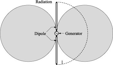
From a radiation perspective, there are two principal characteristics: this antenna does not radiate any field along its axis and presents a radiation pattern symmetrical about its axis. Indeed, this antenna is said to be omnidirectional, i.e. that it radiates a perfectly equivalent level of field magnitude, whatever the direction considered in a plane which is perpendicular to its axis (horizontal if the dipole is vertical, for instance).
From the perspective of bulk, since this antenna comprises only metal, and a single axis, its largest dimension is strictly equal to the half-wavelength in the vacuum.
9.4.2.2. Monopole antenna
Using image theory, we can reduce the bulk of a dipole antenna, subject to associating the antenna to a ground plane of large dimensions (typically several wavelengths). This is the case, for example, for vehicle antennas where large metallic surfaces are available.
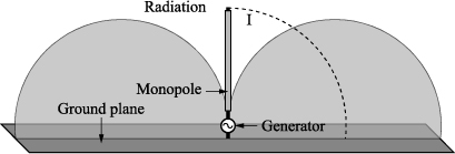
Virtual imaging enables the creation of the equivalent of a dipole from a single one of its arms. As such we refer to a monopole. The monopole has a fundamental mode, corresponding to a total size of λ/4 (see Figure 9.2). This quarter-wavelength monopole offers the same radiation characteristics as the dipole, namely zero radiation at its axis and omnidirectional behavior in the perpendicular plane, but in theory no radiation in the half-space situated below the ground plane.
Figure 9.2. Quarter-wavelength monopole
9.4.2.3. Resonant loop
A resonant loop can also be considered as formed from two metallic arms, fed from the center, but this time closed in on themselves, with now a short circuit and no longer an open circuit condition (see Figure 9.3).
Figure 9.3. Structure of the resonant loop
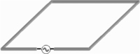
This structure is principally used in two forms: one with four equal sides, one with two parallel arms (one of which contains the source) clearly larger than the others. This latter form, also called a folded dipole, behaves in the same way as the classic half-wave dipole, the total path of the loop being this time equal to the wavelength. The advantage of this folded dipole is that the fundamental mode resonance offers a poorer quality factor and therefore a wider operational bandwidth to compensate for a very slightly larger bulk. In the first form, a loop with a total path equal to λ/2 is not used in practice, since, on the one hand, the resonance, which is parallel this time, produces an impedance that is very difficult to match, and on the other hand the distribution of the currents does not enable very effective radiation efficiency. Conversely, loops with total size λ can be used in a series resonance, offering a radiation pattern that is less omnidirectional than classic dipoles, but with a higher maximum gain and a bulk spread along two dimensions (a square with sides equal to λ/4).
However, loops are generally superseded by planar patch antennas that offer the same advantages while having more degrees of flexibility.
9.4.3. Planar antennas
In this category of planar antennas, we will consider two principal families: slot and patch antennas. We do find within the planar versions dipole antennas in printed circuit technology, but the general behavior remains identical to that previously described.
9.4.3.1. Slots
Slot antennas are vacuums created in plain metal: sheet metal, edge of a waveguide, metallization of a printed circuit board, etc (see Figure 9.4). The Babinet principle established the duality between the vacuum in a conductor and a conductor in a vacuum. It follows then that a slot will present exactly the same characteristics of radiation as its “negative”.
Indeed, in the case of the most classic of the linear slots, these antennas will present the same radiation as the equivalent dipole. The fundamental structure in this case will therefore be a slot of size λ/2, which will present the same radiation pattern as the half-wave dipole, except that here, still following the Babinet principle, the polarization of the radiated field will be orthogonal.
Furthermore, as the metallic and vacuum parts are inverted, the laws of voltage and currents are too, as is the behavior under impedance. This being the case, the fundamental mode λ/2 of the slot corresponds to a very high impedance parallel resonance.
Figure 9.4. Structure of a slot antenna

9.4.3.2. Patches
Printed patch antennas have been widely detailed in previous chapters. They are said to be planar as their vertical dimensions are negligible relative to the other dimensions of the structure that take shape in two dimensions. The most classic patch antennas are rectangular in shape, even though all types of geometry exist.
Figure 9.5. Model of a rectangular patch and its radiation in fundamental mode
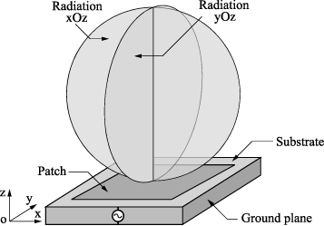
The fundamental mode of this type of structure, the TM10, corresponds equally well to a larger dimension equal to λg/2. For a patch placed in the horizontal plane (see Figure 9.5.), the maximum radiation in fundamental mode is produced at the zenith, with a horizontal polarization.
The patch is a directive antenna with quite a wide aperture. Matching in impedance is easy (see Chapter 6) and the bandwidth is directly linked to the height of the substrate.
Indeed, when the fundamental mode corresponds to a parallel resonance for classic feeding, the quality factor reduces as the height of the patch increases, since the value of capacitance created between the top of the patch and the ground plane reduces (see Chapter 5).
9.4.4. Comparison
We are now able to compare the principal characteristic base antennas. If we take a system working at 1 GHz, the wavelength is thus 30 cm. A half-wave dipole antenna will therefore have a total length of 15 cm, and will offer an omnidirectional radiation pattern (with a maximum theoretical gain of 2.15 dBi).
If the application enables a large ground plane to be used, a quarter-wave monopole will therefore be only 7.5 cm, also with omnidirectional radiation (and a maximum gain of 5.15 dBi).
For the same application, a patch antenna only offers a minimal vertical bulk (typically of the order of 1 mm or even 1 cm for wider band applications). If we use a substrate of relative permittivity equal to 4 (which is a common value), then the patch will have a length of 7.5 cm and a smaller width.
In contrast, it is important to note that the ground plane will need to be bigger than the longest dimension of the patch. This antenna will thus be directive, with a maximum gain of about 8 dBi.
All these antennas can be relatively easily matched over a 50 ohms standard, but offer quite low bandwidths. Choosing between one and another of these structures therefore depends on the application, between linear and surface bulk. As we will see later, the evolution of these base antennas will enable aerial compactness to be increased.
9.4.5. 3D antennas
In the context of strong integration of the antenna in a general device (a terminal housing, for example), it is interesting to make the most of the fact that there are three dimensions. As discussed in Section 9.3, limits are given in terms of volume. In the next part we will detail the case of antennas that are conformed in three dimensions, while emphasizing the various techniques that enable the reduction in bulk of aerials.
9.5. Bulk reduction techniques
The base structures presented previously enable a resonant element to be created in a fundamental mode. In this section we describe the different possible methods of going beyond the limits of classic structures through the use of materials with strong permittivity, the modification of resonator profiles and the utilization of loads or short circuits. Some example structures that allow compactness to be combined with good control of radiation pattern are presented.
9.5.1. Use of dielectrics with strong permittivity
Expression [9.4] shows that we can resort to using a dielectric with strong permittivity as a substrate in order to obtain a resonator with very small dimensions. For example, ceramic materials are able to offer very high values. A relative permittivity of 90 will thus enable a fundamental mode in a dimension of λ0/20.
Unfortunately, the physical properties discussed in Section 9.3 show that the bandwidth and gain of the antenna will be severely limited when the permittivity of the substrate is increased. This same behavior can also be seen in relation to patch antennas in Chapter 5 (Section 5.8). We therefore need to find a compromise: the increase in permittivity may lead to very compact antennas, but this will be offset by poor characteristics of bandwidth and gain being offered.
9.5.2. Modification of wave path
Another approach toward better integration of antennas within compact structures is to modify their profile. Here we are still working on resonators, but we are looking to conform them in such a way that the wave will then follow a path that is no longer linear but best fits the available volume. However, we must not forget that the antenna must not only be brought into resonance, but it must also be an efficient source of radiation. Thus, folding the resonator may lead to a loss in efficiency if the currents on the antenna contribute to the radiation in a destructive way (sources in phase opposition). We are going to describe some structures of conformed antennas, together with the impact on their characteristics of radiation.
9.5.2.1. Inverted L antenna
The so-called inverted L antenna (or ILA) is a quarter-wave monopole where the vertical arm has been bent (Figure 9.6). This very simple structure enables the vertical bulk of the structure to be reduced. However, this change in topology has two impacts. Firstly, the horizontal arm, which is close to the ground plane, is susceptible to instances of coupling; the impedance obtained is therefore different to that of the classic monopole. Secondly, the source radiation currents are now along two orthogonal axes (one vertical and one horizontal arm); the radiation produced is therefore also different, notably with a mixture of vertical and horizontal polarizations.
Figure 9.6. ILA antenna
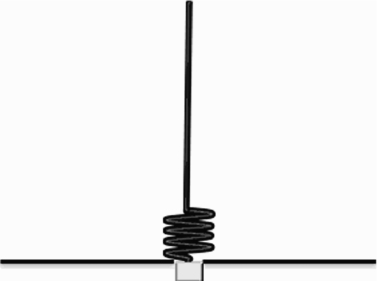
9.5.2.2. Helical antenna
The helical antenna is also a derivation of a quarter-wavelength monopole. The total path of the helix-conformed conductor (see Figure 9.7) is at least a quarterwavelength. However, here the vertical dimension is reduced since the monopole is “compressed”, i.e. wound around a cylindrical shape. The spires created by this winding will also change the impedance, leading to a very low resistance, which generally necessitates an impedance transformer.
Figure 9.7. Helical antenna

In spite of this, the helical antenna is particularly interesting: a correct sizing of the structure enables radiation pattern to be virtually identical to that of the monopole, i.e. perfectly omnidirectional. This structure therefore typically offers a height a quarter of the size, relative to an equivalent monopole.
We note that helical antennas can also be used in another working mode, namely the axial mode, which conversely necessitates an antenna that is large relative to λ, and which therefore is not relevant when discussing compact antennas.
9.5.2.3. Conformed patch antennas
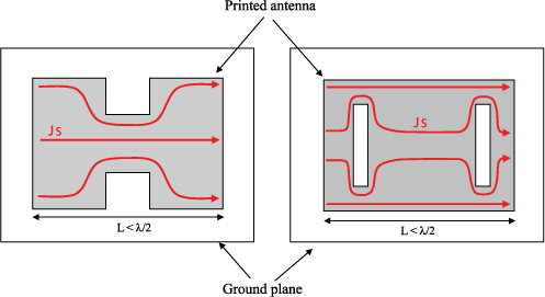
As with wire structures, patch antennas can also be designed in such a way as to extend the path of the currents. Two simple examples are shown in Figure 9.8. The H antenna presents a patch roof, into which two notches are cut. The resonant wave in the structure will then need to follow a longer path between the extremities of the patch, the length of which becomes less than λg/2. The same approach is valid when slots are cut into the patch roof. Notches and slots will modify the imaginary part of the patch impedance in different ways.
The choice of structure may therefore depend on the feed type or the environment near to the antenna (for example, correcting inductive or capacitive coupling). As with the ILA antenna, modification of the current paths will imply a modification of the characteristics of radiation, and particularly the radiation efficiency and purity of polarization.
Figure 9.8. Extending the path of the wave: H antenna (left) and slot—patch antenna (right)
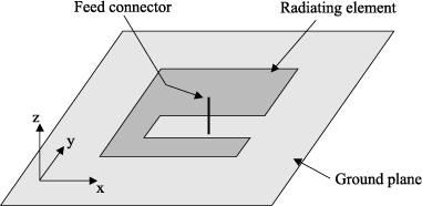
9.5.2.4. C-patch antenna
The C-patch antenna (Figure 9.9) is also a patch antenna whose roof shape has been modified. This particular shape allows an important extension of the path of the wave, which offers a reduction in surface occupied by a factor of 3–4, relative to a classic patch. As before, this strong gain during winding has its compensations: a reduction in the antenna’s bandwidth, as well as an important degradation of the purity of polarization (which is again more significant than in the case of the H antenna).
Figure 9.9. C-patch antenna
9.5.3. Utilization of inductive, capacitive, and short-circuit effects
As with all resonators, the resonant frequency of antennas depends on the value of the equivalent components L and C (inductive and capacitive). One approach for reducing the bulk of antennas is therefore to try to add inductive or capacitive effects that enable the value of the frequency to be lowered, thereby rendering the antenna proportionally smaller relative to the wavelength. Making use of capacitoror inductor-types of components may be a solution, but the general preference is to modify the topology of the antenna in order to create this capacitive or inductive effect locally.
Furthermore, we have seen that the use of the ground plane may allow a reduction in the bulk of antennas. Generally, the use of short circuits in a structure is truly a key factor in reducing bulk. But now, the combination of a short circuit and the effect of the inductive or capacitive coupling that it can produce as a result of being judiciously positioned in the structure lead to structures of antennas that are more compact.
9.5.3.1. Loaded monopole
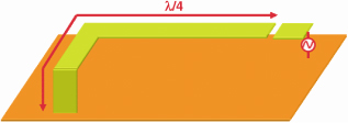
As an example of an antenna that uses a capacitive or inductive effect in order to lower the resonant frequency, we now put forward the case of the quarter-wave monopole. Figure 9.10 shows the case of a capacitive roof placed at the top of a monopole, in order to create an overall increase in the value of resonator capacitance, and therefore a reduction in the resonant frequency. The second case, which is presented in Figure 9.11, is of a monopole consisting of a series induction coil at the base of the radiating arm that also enables a shorter antenna to be obtained.
Figure 9.10. Monopole loaded by capacitance
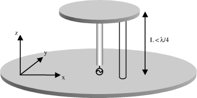
Figure 9.11. Monopole loaded by inductor (whip monopole)
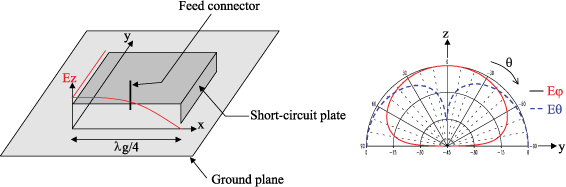
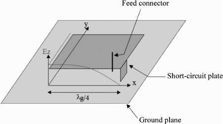
9.5.3.2. Quarter-wave patch
As its name suggests, the quarter-wave patch uses a short-circuit plane in order to enable the transformation of the half-wave resonance mode of the classic patch in quarter-wave mode (being based therefore on the electrical image created by the ground plane as a result of image theory). A patch that is twice as short results from this, but with a degradation of radiation characteristics.
As we can see in Figure 9.12, the short-circuit plane, which contains strong current densities, will produce a significant vertical component to the detriment of the pure horizontal polarization of the half-wave patch.
Figure 9.12. Quarter-wave patch and associated radiation pattern in the plane xOz
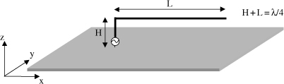
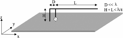
9.5.3.3. Inverted F antenna
The inverted F antenna (Figure 9.13), or IFA, is the equivalent of an ILA antenna with a short circuit added. Not only will this short circuit allow the virtual extension of the wave path, but furthermore the positioning of the feed wire in parallel with this short circuit enables the creation of an inductive coupling effect.
As with loaded monopoles, this additional self-inductance enables a lowering of the resonant frequency of the structure, and therefore the achievement of a shorter antenna.
We will detail the evolution of the IFA antenna in terms of planar technology, the PIFA, in the next section.
Figure 9.13. Inverted F antenna
9.5.3.4. PIFA
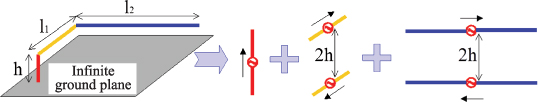
The acronym PIFA stands for planar inverted F Antenna as the antenna when viewed from the side is always in the shape of an overturned letter F [DRE 05]. A common PIFA (see Figure 9.14) comprises a rectangular plate of dimensions L1 × L2, a ground plane and a short-circuit plane that links the plate to the ground plane. The width of the short-circuit plane W varies from L1 to 0 (wire). Since this antenna is nowadays one of the most used structures in the integration of very compact antennas, we are going to focus a little more on the details.
Figure 9.14. PIFA antenna
The resonant frequency of a PIFA depends on a number of parameters. If we consider the PIFA on an infinite ground plane, the resonant frequency of the antenna varies according to the width of the short-circuit plane, relative to the width of the plate (W/L1) and according to the ratio between the length and width of the plate [HIR 92]. In practice, we hardly ever encounter an infinite ground plane. As a consequence, the dimensions and shape of the ground plane may strongly affect the value of the resonant frequency. Furthermore, the position of the feed point also has a strong bearing on the resonant frequency of the antenna.
When W/L1 = 1 (i.e. the width of the short-circuit plane is equal to the width of the plate), the resonant frequency is defined by the following expression:
[9.5] ![]()
When W = 0 (i.e. the short circuit is effected by a wire), the resonant frequency is defined by the following expression:
[9.6] ![]()
When 0 < W/L1 < 1, the resonant frequency is defined by the following expression:
[9.7] ![]()
and:
[9.8] ![]()
where r = W/L1, k = L1/L2, the frequency f1 is defined by the relationship L2 + H = λ/4 and f2 is defined by the relationship L1 + L2 + H − W = λ/4.
Apart from the resonant frequency, another significant parameter in antenna design is bandwidth. Once more, in the case of PIFA antennas, it is possible to optimize bandwidth by modifying certain parameters: essentially the height and dimensions of the plate and the width of short-circuit plane. The larger the ratio between the width and the length, the greater the bandwidth. Similarly, for a given plate width and length, it is possible to improve the bandwidth by increasing the height of the plate, relative to the ground plane. The principal disadvantage of the PIFA antenna is its poor control over its radiation pattern and a much-degraded purity of polarization. However, this aspect is often masked when strong integration is required.
9.5.4. Control over radiation
As we have just seen, a preference toward extremely compact structures generally induces degradation in the characteristics of radiation. However, some structures are able to be compact and still maintain control over radiating fields. Here we look at two cases: one antenna enabling a tendency toward a perfectly isotropic radiation pattern [VIL 02], and another enabling omnidirectional radiation with very good purity of polarization [DEC 02].
Figure 9.15. 3D folded strip antenna
9.5.4.1. Folded quarter-wave resonator
In order to combine the appeal of the compact resonator with a radiation pattern where we can control the characteristics, the structure is folded along three orthogonal axes (see Figure 9.15). In practice, this type of resonator is usually produced using microstrip technology. In order to maintain the linear current distributions, these strips must be relatively narrow, thus leading to a resonator with a fairly high quality factor. An approach involving feed by capacitive coupling enables us to easily return to a matched structure.
This structure therefore enables us to simply obtain small lateral dimensions, along with good impedance matching. However, beyond this, imposing three orthogonal axes on the elements of the resonator also offers the option of sizing these elements based on a constraint of radiation, such as isotropic radiation (which is the subject of [JEC 02]), i.e. an equivalent level of radiated field in every direction in the space. This isotropic constraint is expressed through a criterion of maximum variation in the gain in the overall space of the order of 3 dB (which is in reality a half-space if we consider an infinite ground plane ). Optimization of the parameters (values h, l1, and l2 in Figure 9.16), while considering each arm of the structure to be a radiating element with the current intensity of current corresponding to a quarter-wave mode, gives the following values: h = λ/24, l1 = λ/15, and l2 = λ/7 [VIL 02]. We then obtain an antenna whose biggest dimension is λ/7, which brings about an isotropic radiation. Nevertheless, it should be noted that this radiation is uniform in terms of power, if not in terms of polarization.
Figure 9.16. Contribution of the different antenna arms on radiation
9.5.4.2. Wire-patch
Another topology that enables compactness and purity of radiation to be combined is the wire-patch antenna [DEC 02]. The principal elements are summarized in Figure 9.17. In its most classic form, the structure of this antenna is identical to that of a printed patch antenna. It comprises an arbitrarily shaped metallic patch that is positioned on the upper surface of a dielectric cell. The lower surface of this cell is entirely metallized and constitutes the ground plane of the antenna. Feeding is achieved by a coaxial connector that crosses the ground plane and the dielectric substrate in order to be connected to the upper metallic element (which is called the capacitive roof).
The characteristic feature of this antenna is that it possesses one or more wires connecting the antenna roof to the ground plane. These wires are often called grounding or short-circuit wires. The presence of these wires close to the connector is the key to the unique workings of the antenna. Without the grounding wire, the antenna behaves as a series resonant circuit due to the self induction from the feed connector and the capacitance formed by the upper roof. Adding a grounding wire to the antenna then leads to the appearance of parallel resonance at the same point as the series resonance previously quoted (Figure 9.18).
Figure 9.17. Wire-patch antenna
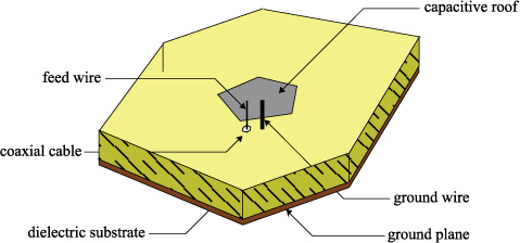
Figure 9.18. Equivalent circuit of wire-patch antenna
This is explained by the fact that induction of the lead-in ground wire shorts the antenna capacitance the antenna capacitance formed between the ground plane and the upper roof. The majority of surface densities of currents circulating around the antenna are, moreover, particularly concentrated on the short-circuit wire.
This resonance mode therefore occurs at a much lower frequency to that of the patch, λ/2 in fundamental mode (approximately four times lower). The dimensions of the antenna are therefore particularly low relative to the working wavelength, since they are verified according to square antennas of wavelength l and height h:
[9.9] ![]()
A complete study of the parameter keys of such a structure can be found in [DEC 02], for which Table 9.1 offers a summary.
Table 9.1. Influence of the parameters of the wire-patch antenna
An additional point about this wire-patch antenna concerns its characteristics of radiation. Effectively, its topology causes the short circuit to condense the strongest current densities. This results in radiation that is virtually equivalent to that of a classic quarter-wave monopole (see Figure 9.19). We therefore obtain a perfectly omnidirectional antenna, with a maximum gain of the order of 5 dBi and a very pure vertical polarization. It is interesting to note that the wire-patch antenna can be used with a reduced ground plane, which is barely bigger than the roof, and that in this situation we can move toward a dipolar pattern (which is equivalent to that of a half-wave dipole).
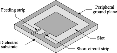
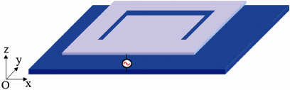
9.5.4.3. Coplanar wire-patch
A declination of the principle of the wire-patch antenna is the coplanar wirepatch (see also [DEC 02]). This refers to a structure where all of the elements of the wire-patch are transposed into a single plane in order to obtain a 2D structure (see Figure 9.20). Instead of having a ground plane positioned under the roof of the antenna, the bulk of the structure occurs around the capacitive roof, and the feed and short-circuit wires are replaced by strips, all within the same plane. As with the classic wire-patch, the essential currents are concentrated in the short-circuit strip. As the ground plane is heavily reduced, the antenna offers dipolar radiation. Conversely, as the ground plane is around the antenna, its bulk is increased, and we obtain maximum dimensions of the order of λ/3.5 (which remains clearly less than a classic patch antenna).
Figure 9.19. Radiation of the wire-patch antenna over an infinite ground plane
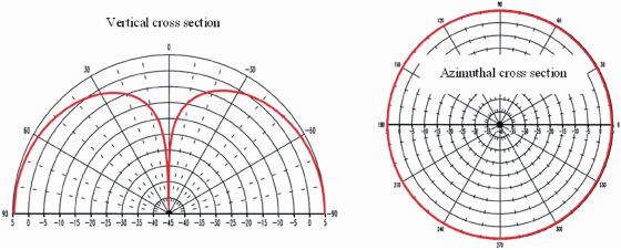
Figure 9.20. Coplanar wire-patch antenna
We can also see that this coplanar principle can be transposed to other topologies (such as PIFA, folded quarter-wave, etc.), which also leads to an increase in area but which also enables the lower ground plane to be suppressed.
9.6. Multiresonant antennas
In the context of the integration of antennas in a communicating housing, it is quite often necessary to multiply the range of frequencies, in order to offer access to several communication standards or to widen the general operating band of the system. Although they are practical to integrate, resonant antennas are limited in terms of bandwidth by their quality factor. It is often the case, therefore, that more than one resonance (or more than one resonator) will be used, in order to enable either the operating band to be widened (as in a wideband system) or multifrequency operation.
In order to widen the bandwidth of an antenna, we look for the structure to present two resonances (which would usually be parallel) that are sufficiently close in frequency for the impedance of the antenna to remain matched over a wider spectrum. For example, we can refer to the example of the U slot patch antenna (see Figure 9.21). The patch offers its classic λ/2 resonance mode, but the slot fitted into its roof will also come into resonance. If the slot path is correctly adjusted then the coupling of these two resonances enables us to obtain a unit-operating band that is clearly wider. However, we must pay attention here to the characteristics of radiation. We will therefore attempt to bring together resonance modes providing similar characteristics of radiation, so that the final antenna keeps an identical radiation pattern over the whole range of frequencies.
Figure 9.21. U slot patch
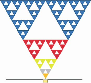
Clearly this principle can be extended to cater for more than two resonances. In the context of applications such as those defined for UWB, which by definition cover a very wide spectrum, some antenna structures can be based on a combination of multiple resonances with severely degraded quality factors. A first example is the use of fractal structures, where the motif, which is repeated over a range of scales, therefore offers multiple resonances within the spectrum (see Figure 9.22).
However, we can equally use a combination of resonators in order to offer several distinct operating bands. The logical approach is first to design an antenna that can operate in the lowest band, which can subsequently be integrated (without increasing the general bulk) with another resonator for a higher frequency band (which is therefore a priori less bulky). Still with the example in Figure 9.21, we can deliberately design a shorter slot, which will present a resonance mode with a higher frequency.
Figure 9.22. Fractal antenna (Sierpinski)
Within this logic of integrating several resonators, we can also differentiate between multiband designs (where all resonators should have equivalent radiation in different bands) and multifunction designs (where resonators are able to offer completely different types of radiation). Moreover, within a single structure, we look for the different modes to be fed from one single connector (as with the U slot patch), or conversely to have a feeding port for each operating mode. It is useful to able to design antennas with a single port, but that then assumes that it is possible to filter out the different bands received.
In the case of diversity systems, which therefore require several antennas to provide several independent copies of the same signal, it is imperative that we separate the ports, but also that we see to it that the coupling between these modes is as low as possible. In order to enable assistance in the integration of diversity systems in reduced bulk, priority will be given to either pattern diversity (thus two resonators with complementary radiation patterns) or polarization diversity (two modes with perfectly orthogonal polarizations). For example, dual-polarized patches can offer two perfectly uncorrelated channels, without having to increase the bulk of the antenna.
9.7. Synthesis and discussion
This chapter has enabled us to work our way through the range of principal structures of antennas that are used in order to integrate wireless links into compact devices. The elements best suited to this type of integration are essentially resonators. Whatever the choice of resonant system, a compromise is necessary between general size of the antenna, its bandwidth, and its characteristics of radiation. It is possible to move toward extreme miniaturization, for example by using dielectrics with very high permittivity, but that would inevitably have an effect on the antenna performance, in terms of impedance or efficiency of radiation.
Over and above the different families of antennas described, some common approaches can be retained: conforming the antenna in three dimensions, resorting to short circuits and modifying the inductive and capacitive effects within the body of the structure. One of the most popular structures, which combines these three approaches, is the PIFA antenna. However, the wire-patch antenna also allows very strong compactness while preserving a better control of radiation.
Finally, the combination at the core of a single structure, with several elements being in resonance, is key in developing new multistandard or diversity systems. The more these systems increase in complexity, the more it is necessary to very precisely design their structure, while taking into account their working environment: a housing in which they will be integrated, related elements (radio card, batteries, etc.), CEM constraints, etc.
New approaches exist that have not been mentioned here: utilization of purely dielectric resonators, magneto-dielectric substrates, or even meta-materials. We hope from this that a number of these techniques will enable the compactness of future antennas to be improved still further.
1 Chapter written by Guillaume VILLEMAUD.