

Input / Output Organization 241
For example ( Figure 8.3 ), if devices A and B are to communicate in asynchronous manner (assum-
ing data ow from A to B), then initially A asks B (through some signals) ‘ Are you ready? ’ Device A
now keeps on waiting till it gets the reply from B like ‘ I am ready ’. Once it is assured that B is ready to
accept, A sends data proper along with another signal, which may be interpreted as ‘ Here is the data,
please accept it ’. After receiving the data, device B nally sends the acknowledgement signal to A, as
if saying ‘ I have received the data, thank you ’. After receiving this acknowledgement signal from B, A
start sending another set of data. Note that in this communication, the start of each phase is dependent
upon proper completion of the previous phase. A will not send another fresh set of data until it receives
the acknowledgement signal from B. Therefore, in asynchronous communication, extra handshaking
signals are necessary to complete the process without any fault, in spite of two devices operating under
different clock frequencies.
The above example of asynchronous data transfer between A and B is pictorially represented through
Figure 8.3 . This is a timing diagram, which represents signal changes with respect to time. The arrows
with a bubble at starting represent the cause and effect or in other words, the correlation between signal
changes. The bubble represents the cause and the arrowhead represents the effect. For example, we may
point out that the handshaking signal from B to A would go low only when B has received the handshak-
ing signal from A, being changed from high to low. Similarly, data will remain valid (unchanged) till A
receives the acknowledgement signal from B in the form of low-to-high transition.
It is already pointed out that asynchronous communication is essential when two devices are operating
in different clock frequencies. Example of these cases may be taken as the communication between the
computer and the printer or the communication between the computer and the keyboard. Both printer as
well as keyboard have their own processors inside, operating with their own individual frequencies, which
is different from the frequency of the processor inside the computer.
8.4 SERIAL AND PARALLEL COMMUNICATIONS
Asynchronous communication may be further classi ed as serial and parallel, depending upon number
of bits being transferred at the same instant. In serial communication, only one bit of information is
transferred at a time, while in parallel communication, multiple bits, generally 8 or 12 or 16, are trans-
ferred at the same time. Therefore, the requirement of number of transmission lines necessary to connect
two communicating devices would be less for serial communication than that is required for parallel
communication. However, the speed of data transfer would be faster in case of parallel communication
than the speed of serial communication.
From our common sense, we may conclude that an 8-bit parallel communication would be eight
times faster than serial communication. However, if we take into account the addition and then
deletion of start bits and stop bits and the number of bits to be transmitted per byte in serial
communication, we shall find that 8-bit parallel communication is more than eight times faster
than serial communication.
F
O
O
D
F
O
R
T
H
O
U
G
H
T
M08_GHOS1557_01_SE_C08.indd 241M08_GHOS1557_01_SE_C08.indd 241 4/29/11 5:14 PM4/29/11 5:14 PM
242 Computer Architecture and Organization
8.4.1 Format of Serial Data Transfer
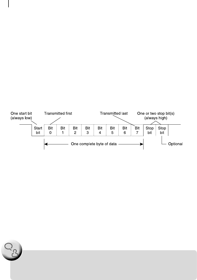
In the case of serial communication, as the information to be transmitted or received one bit at a time, a
byte of information is broken and sent bit-by-bit, as shown in Figure 8.4 , with least signi cant bit (bit 0)
transmitted rst and most signi cant bit (bit 7) transmitted last. At the receiving end, transmitted bits are
sampled at the middle of their transmission. Note that one start bit and one or two stop bit s are added with
every byte of transmitted data. This start bit has always the same logic level as that of logic 0, i.e., the start
bit is always low. On the contrary, the logic of stop bit(s) would always be high (1). Therefore, if one stop
bit is used, to send one byte of information, 10 bits and not 8 bits must be transmitted.
In serial communication, the rate of data transmission, known as baud rate , has some standard val-
ues. These values are 300, 600, 1200, 2400, 4800, 9600 and 19200 bits per second (bps). In its true
meaning, the unit ‘bits per second’ means ‘s ymbols per second’ as the start and stop bits are included
with eight bits of every byte of transmitted data. For example, if the baud rate is xed as 300 bps and
only one stop bit is used along with one start bit, then, in one second 30 bytes of data would be trans-
ferred because to transfer each byte, 10 bits must be communicated.
Figure 8.4 Format of serial data transfer
These start and stop bits are added with data bytes before the transmission and deleted from the
received data to regain the transmitted byte after data reception. As the distance to be covered by trans-
mission is larger in the case of serial communication used in computers, the signals are generally buff-
ered and biased to eliminate noise and other transient disturbances.
8.4.2 USART
As we may easily understand, it is too much time-consuming for any processor at the transmitting end to
load every byte to be transmitted (from memory), break it into several bits, add start bit and stop bit(s)
and nally transmit all these, one bit at a time. The same is also valid if the processor is at the receiving
end. In that case, it has to discard the start bit and stop bit(s), assemble each byte, bit by bit, and then
As the USART is mostly used for asynchronous communication and very rarely employed for
synchronous communication, generally, it is designated as UART i.e., universal asynchronous
receiver transmitter.
F
O
O
D
F
O
R
T
H
O
U
G
H
T
M08_GHOS1557_01_SE_C08.indd 242M08_GHOS1557_01_SE_C08.indd 242 4/29/11 5:14 PM4/29/11 5:14 PM

Input / Output Organization 243
store it at certain location of memory or use it for some immediate purpose. Therefore, the general prac-
tice is to use a standard universal synchronous asynchronous receiver transmitter (USART) and relieve
the processor from its extra burden of serial communication.
Essentially, any USART (or UART) has one transmitting terminal (known as TxD) and another
receiving terminal (known as RxD) at its external end. These terminals must be interfaced with simi-
lar and appropriate terminals of another USART at the other end of communication ( Figure 8.5 ). The
internal end of USART has necessary terminals so that it may be interfaced with its processor through
address, data and control signals of the CPU bus. Internally, the USART has at least two buffers, one for
input and the other for output. The processor writes data byte, which needs to be transmitted out through
serial interface, within this output buffer. Thereafter, it is the duty of the USART to send the data byte
out as per the prescribed baud rate, completing all other necessary formalities.
Figure 8.5 Schematic of serial communication using USART
Similarly, the receiving buffer of the USART keeps on collecting the serially received data, bit by bit,
and when it has collected all eight bits, the processor reads this input buffer. Here, the processor must be
very alert to read the incoming byte immediately, as the bits of next byte would also be collected within
the same receiving buffer of the USART. To eliminate this problem, some USARTs offer double buffers
for data receiving. When the receiving buffer is full, the complete byte is copied to the second buffer
and the receiving buffer keeps on collecting fresh incoming bits, offering the CPU more time to read the
just-stored byte of information.
8.4.3 Intel 8251 USART
Intel 8251 is one such USART, which offers double buffers for serial data receiving and may be inter-
faced with any Intel processor. A schematic representation of internal architecture of Intel 8251 USART
is presented in Figure 8.6 .
As we may observe from Figure 8.6 , one buffer each for data transmission and reception are con-
trolled by respective control units. Apart from these, the modem control block deals with the handshak-
ing signals, namely RTS, CTS, DTR and DSR. These signals would be necessary only if any modem is
used for communication. Modems are necessary if serial communication links to be established through
a telephone line. Functional characteristics of these signals are brie y described below.
Data Terminal Ready (DTR) is an output signal from USART, which is activated (goes low) whenever
any terminal is powered up and ready to accept or transmit data from/to external source through its RxD
input or TxD output.
Data Set Ready (DSR) is an input signal received by USART, generally, from the modem, as an indica-
tion that the modem is ready to communicate with the USART.
Ready To Send (RTS) is an output signal to the modem indicating that the USART is about to send
the data to it. RTS goes low to indicate this, and after completion of all data transactions RTS goes high
again, indicating end of data transmission.
M08_GHOS1557_01_SE_C08.indd 243M08_GHOS1557_01_SE_C08.indd 243 4/29/11 5:14 PM4/29/11 5:14 PM
..................Content has been hidden....................
You can't read the all page of ebook, please click here login for view all page.