
244 Computer Architecture and Organization
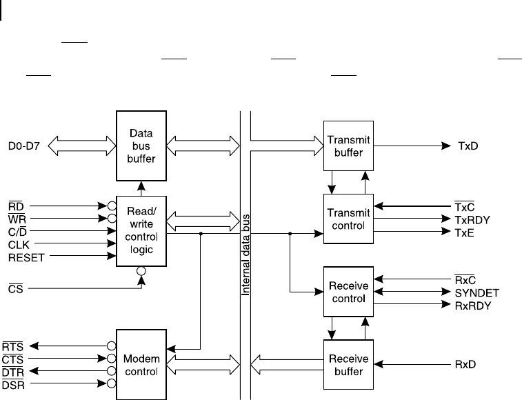
Clear To Send (CTS) is the input signal, generally, comes from the modem as the indication that the
modem is ready to accept the data. CTS goes low after RTS goes low and it stays low as long as RTS is
low. After RTS goes high indicating the end of data transmission, CTS also goes high.
Figure 8.6 Schematic of Intel 8251 USART
Signals RxRDY, TxRDY or TxE may be used to interrupt the processor indicating the time for
further data communication with the respective buffers. We shall discuss these interrupt related issues
in the section of interrupt driven I/O of this chapter after completing discussions on Programmed I/O.
8.5 PROGRAMMED I/O (POLLING)
As we have already indicated, for programmed I/O, a complete attention of the processor is essential for the
data communication, which is not so in the case of interrupt driven I/O, as we shall discuss in Section 8.6.
Programmed I/O is also designated as polling method of data transfer or simply by the term polling .
8.5.1 Sending Data Out
It is simpler to send any data out by programmed I/O than to receive it. In this case (to send the data
out), the processor simply writes the relevant data in the latch of the output port. The data is immedi-
ately available at the outer end of the port latch communicating with the external world. This output
data may be for turning on or off an array of LEDs or to start or stop some motors or pumps. Note that
in the latter case, proper interfacing is essential to drive the heavy duty units through the digital port.
However, we should keep in mind that in case of programmed output, the processor need not waste any
time for outputting the data unless it is a case of asynchronous data communication, which we have
already discussed. How is it possible that in the case of programmed output the data transfer is almost
instantaneous? This is because the output data is always latched by the output port .
M08_GHOS1557_01_SE_C08.indd 244M08_GHOS1557_01_SE_C08.indd 244 4/29/11 5:14 PM4/29/11 5:14 PM
Input / Output Organization 245
8.5.2 Receiving Data In
The situation is not so in case of receiving any data through programmed I/O. Because the data is
expected to be generated from some outside source, which is generally beyond the control of the pro-
cessor, the processor simply waits to receive the data through the port or in other words, keeps on read-
ing it . A common example to visualize the situation may be the input through an external key (not of
the keyboard, which is generally interrupt driven). In this case, at what time the key would be pressed
by the user, is unknown to the processor and it simply keeps on reading the input port continuously till
there is any change of the interfaced key’s status detected by the processor. To eliminate this problem,
sometimes a strobe-signal is used to latch the input data within the input port so that the processor
may read it at its own convenient time. For some input ports in some modes, this strobe-signal not
only latches the data but also generates an interrupt signal, e.g., Intel 8255 programmable peripheral
interface (PPI), which we shall take as an example case for discussions on both programmed as well
as interrupt driven I/O.
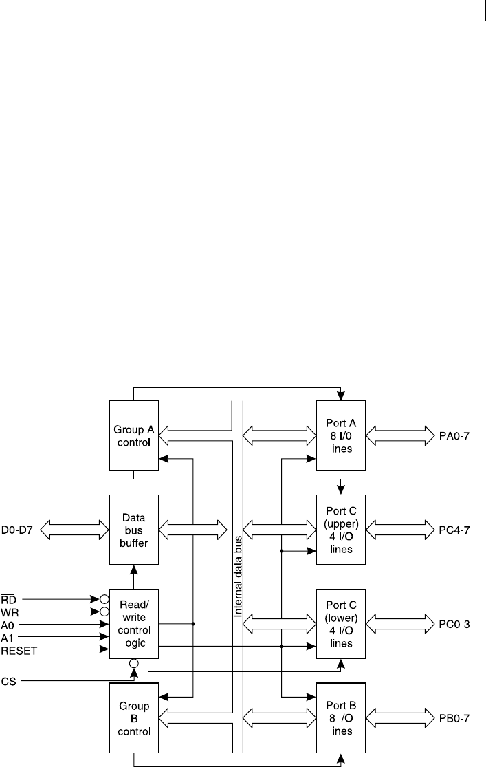
8.5.3 Intel 8255 PPI
A schematic of internal architecture of Intel 8255 PPI is presented in Figure 8.7 . This device offers three
8-bit I/O ports, designated as A, B and C. For easier operation, these ports are divided in two groups,
A and B. Port A along with upper four bits of Port C form group A, and Port B along with lower four
Figure 8.7 Schematic of Intel 8255 PPI
M08_GHOS1557_01_SE_C08.indd 245M08_GHOS1557_01_SE_C08.indd 245 4/29/11 5:14 PM4/29/11 5:14 PM
..................Content has been hidden....................
You can't read the all page of ebook, please click here login for view all page.