

Input / Output Organization 251
8.8 DMA
In the previous chapter (Section 7.8.1) we have introduced the concept of DMA and discussed about some
details of its execution using a le-reading example. As already indicated, DMA is generally implemented
when a large volume of data have to be transported from one place to another. DMA is not observed to be
economical for transporting only a few bytes of information. Some of the features of DMA, not explained
in Chapter 7, would be discussed here using Intel 8237 DMA controller as an example device.
8.8.1 Intel 8237 DMA Controller
Although during the DMA procedure, the DMA controller represents all actions on behalf of the proces-
sor, it is always controlled by the processor and that is the reason for assigning an I/O device label to
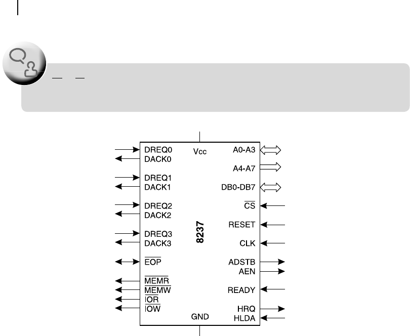
a DMA controller. Referring to Figure 8.12 , we may observe that the CS input, which indicates that it
is treated as a peripheral device. Apart from the CS input, we should also discuss about certain signals,
depicted in Figure 8.12 , for a better understanding of functioning of the 8237 DMA controller, which
we have skipped in Chapter 7 during the DMA discussions.
Figure 8.11 Multiple 8259s in cascade configuration
M08_GHOS1557_01_SE_C08.indd 251M08_GHOS1557_01_SE_C08.indd 251 4/29/11 5:15 PM4/29/11 5:15 PM
252 Computer Architecture and Organization
The most interesting part of the DMA controller is that it has a bidirectional address bus of four address
lines, A0 to A3, as shown at the top right corner of the diagram. We know that for all peripheral and mem-
ory devices, and also for the processor, the address bus is unidirectional. We also know that the address
signals are generated only by the processor and received by all other peripheral devices. Then why the four
address lines are bidirectional for a DMA controller? The answer is that although in normal (non-DMA)
situation, it functions like any other peripheral device and receives address signals from the processor, dur-
ing DMA operation it functions like a processor and emits all 16 address signals. The lowest four address
lines (A0 – A3) becomes common for these two cases and, therefore, must be bidirectional. Note that as
a peripheral device, 8237 needs only four address inputs to target its internal registers. However, during
DMA operation it is capable of generating all 16 address signals from A0 to A15.
This last statement may generate another question. From Figure 8.12 , we may observe that 8237 has
only eight address lines, out of which four (A0 – A3) are bidirectional and A4 – A7 are unidirectional,
coming out from the DMA controller. Then, what about the remaining eight address signals, from A8
to A15? The answer is, they are multiplexed with the data bus, designated as DB0 – DB7. These higher
order address signals may be de-multiplexed from the data signals using the ADSTB signal generated
by 8237, during the DMA operation.
CS or CE inputs are never associated with any processor. This label or input is only for memory
and other peripheral ICs.
F
O
O
D
F
O
R
T
H
O
U
G
H
T
Figure 8.12 Schematic of signals of DMA controller 8237
M08_GHOS1557_01_SE_C08.indd 252M08_GHOS1557_01_SE_C08.indd 252 4/29/11 5:15 PM4/29/11 5:15 PM
..................Content has been hidden....................
You can't read the all page of ebook, please click here login for view all page.