
Pipelining 375
the boundary conditions vary, imposing dif culties for smooth and continuous execution of different
cycles of various instructions available within the pipeline. The reason behind these obstructions may
be different but their result is the same, i.e., an instruction’s execution is not complete within the pre-
de ned time. In general, these reasons maybe one of the following three types:
R Data hazard
R Instruction hazard or control hazard
R Structural hazard .
Data hazard occurs due to non-availability of some data on-time. In general, it is a result of data depen-
dency. Instruction hazard (also known as control hazard ) is because of non-availability of the instruction
on-time. The reason for structural hazard is the non-availability of some hardware resource necessary for
two or more instructions. We shall now discuss these individual cases in the following sections.
12.4 DATA HAZARDS
In pipeline architecture, data hazards are, generally, encountered whenever the necessary data for pro-
cessing is not available at the stipulated time. The reason may be a data dependency or an I/O wait or
something else. In this section, we discuss the rst two.
12.4.1 Data Dependency
In most of the cases, data hazards occur whenever there is a case of data dependency. What is meant by
data dependency? It means the result of some arithmetic or logical operation is the operand of the next
instruction. As an example, we may consider the following two instructions to be executed in the same
sequence as they appear in the text.
Instruction 1: X ← X+3 [Replace X by X+3]
Instruction 2: Y ← Y+X [Replace Y by adding Y with X]
If the present value of X is 1 and Y is 7 before execution of the rst instruction, then after execution
of the rst followed by second instruction, X would be 4 and Y would be 11. However, in a 5-stage pipe-
line (Figure 12.4 ), the execution of rst instruction and operand fetch of the second instruction would
be performed concurrently by the processor. Therefore, at the time of execution of the second instruc-
tion X would be taken as 1 and not 4, resulting in an incorrect value of Y as 8. This simple example
illustrates one very important fact that whenever there is a data dependency, the related instructions
must be executed in proper sequence and the operand fetch must wait till the availability of the correct
result from the previous instruction . Therefore, in pipeline architecture, data hazards means waiting time
of the processor for the availability of correct data (generally, as a result of some previous operation)
to be used as operand(s) for the ongoing instruction’s execution. To come out from this hazard, either
software or hardware method may be adopted.
12.4.2 Solution by Software Method
In the software method, one or two NOP instructions (no-operation) are inserted by the compiler after
those critical instructions, whose results would be used by the following instruction. In our example
case, described above, this would result in a structure of
M12_GHOS1557_01_SE_C12.indd 375M12_GHOS1557_01_SE_C12.indd 375 4/29/11 5:24 PM4/29/11 5:24 PM
376 Computer Architecture and Organization
X ← X+3
NOP
NOP
Y ← Y+X
The reader must have realized by now that the execution of these additional NOP instructions after
rst instruction ensures that during the operand fetch cycle of the last instruction (Y←Y+X), result of
the rst instruction would be in correct place so that the accuracy of the result is not affected.
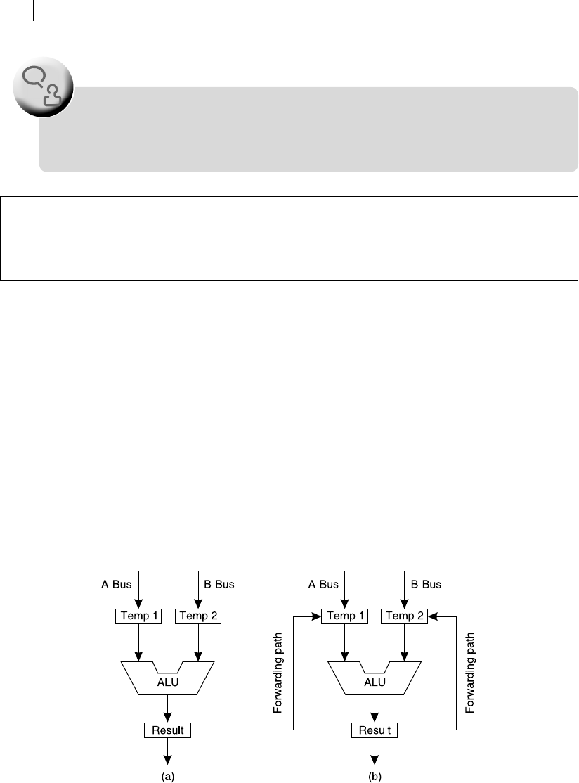
12.4.3 Solution by Hardware Method
In the case of hardware method, to avoid data hazards, generally, extra data paths are provided from the
result register of ALU to its input registers. In normal operation, this path remains unused. However, in
the case of data dependencies, the path is opened by the appropriate control signal from the control unit,
so that the result from ALU is immediately available as one of the operands to the ALU again. This path
is designated as forwarding path and the process is known as operand forwarding .
Figure 12.7 illustrates the same ALU structure (a) without and (b) with forwarding paths. Note that
the input registers of ALU, designated as Temp 1 and Temp 2, are interfaced with the set of registers and
other parts of the processor through the A-bus and B-bus, as we have already discussed in Chapter 10.
Providing additional paths or forwarding paths to cater to the cases of data dependency
should be carefully evaluated by the designer as there are chances of malfunctioning of ALU
output due to unpredictable alternations of input operands.
F
O
O
D
F
O
R
T
H
O
U
G
H
T
Figure 12.7 ALU (a) without and (b) with forwarding path
C-Bus C-Bus
M12_GHOS1557_01_SE_C12.indd 376M12_GHOS1557_01_SE_C12.indd 376 4/29/11 5:24 PM4/29/11 5:24 PM
..................Content has been hidden....................
You can't read the all page of ebook, please click here login for view all page.