

Pipelining 383
may also be performed independently and the related control signals generated are stored within its buffer.
This decoding activity also does not hamper the working of any other modules. Operands for Instruction
3 may be collected through data memory register (read) from the data cache and placed within the register
array, another independent operation. Execution of Instruction 2 involves the ALU, its temporary registers
and its result register and no other part of the circuit. Finally, storing the result of Instruction is performed
using MAR(D), which would be the nal independent operation. Therefore, in the 5-stage pipeline, all
operations may be performed concurrently, which ensures the basic demand of pipeline architecture.
12.8 PENTIUM 4 PIPELINE
In a miniature form, only a smaller fraction of pipeline architecture was introduced for the rst time in
Intel processors through 8086 in the form of its 6-byte instruction queue. As we know, 8086 was intro-
duced in 1978 and from that time till today, Intel processors traversed a long journey of modi cations,
including re nements of the pipeline architecture. Table 12.1 presents a brief indication in pipeline
advancements in Intel processors starting from 8086.
Processor Introduced in No. of pipeline stages Remarks
8086 1978 – Six-byte instruction queue
80286 1982
80386 1985
80486 1989 5 Fetch, Decode 1, Decode 2, Execute, Write Back
Pentium 1993 5 Two 5-stage pipelines (u-pipeline and v-pipeline)
Pentium Pro 1995 14
Pentium II 1997 7
Pentium III 1999 10
Pentium 4 2000 20
Itanium 2001 10
Itanium 2 2002 32
Core2Duo 2006 14 Each core with 14-stage pipeline
Table 12.1 Pipeline characteristics of Intel processors
One important observation from this table is that the number of pipeline stages must be optimum. Too
less as well as too many stages may not produce the desired result of pipeline with respect to the dif culties
undertaken for its design and implementation. In this section, we restrain our discussions on Pentium 4 pipe-
line. Characteristics of few more pipelines of other processors would be available in different appendices.
12.8.1 Why RISC-like-CISC
In Chapter 5 (Section 5.12.1), we have discussed about RISC-like-CISC architecture adopted for Pentium-
series processors. We have indicated there that in spite of offering a comprehensive instruction set, these
processors adopted several RISC-like features, e.g., pipelined architecture, cache memory, larger number
of internal registers and super-scalar architecture. However, the most important RISC-like feature of these
Pentium-series processors is the micro-coding, which had been designed to break-down all instructions to
M12_GHOS1557_01_SE_C12.indd 383M12_GHOS1557_01_SE_C12.indd 383 4/29/11 5:24 PM4/29/11 5:24 PM

384 Computer Architecture and Organization
RISC-like micro-codes before execution. Number of these micro-codes is much less as compared to the
number of related instructions. This gives an edge in micro-operations resulting in faster execution speed
of the processor. As we have introduced the micro-coding concepts in Chapter 10, these characteristics
of Pentium processors were not included in discussions on Pentium in Chapter 5 and was expected to be
presented in this chapter. However, one important technique implemented in Pentium 4 pipeline demands
some elaboration. The technique we are about to discuss is generally designated as out-of-order execution .
12.8.2 Out-of-order Execution
As we know that, in general, instructions are executed in the same sequence as they appear in the source
code. This method does not create any problem where only one execution is carried out at a time. How-
ever, processors with pipeline architecture place multiple instructions simultaneously within the pipeline
as we have already explained. Furthermore, in Chapter 13, we shall see that for super-scalar operation,
processors grab multiple instructions simultaneously and feed the pipeline with those instructions. In all
such cases, where multiple instructions are being executed by the processors concurrently, many proces-
sors do not follow the same order of execution as it appears in the original source code (Input). This is
known as out-of-order execution, which speeds up the execution in normal cases. However, we must keep
in mind that where there is some data dependencies, this out-of-order execution cannot be implemented.
For the sake of an example, let us consider the following program steps. We assume the name of the
general purpose registers of the processor as R0, R1, R2 and so on up to R7. Instructions are presented
in their pseudo-codes with comments in parenthesis by their side. Instruction step numbers are indicated
at the left of every instruction.
Step 1 R4 ← R4 + 10 {Add 10 with R4}
Step 2 R5 ← R5 + 20 {Add 20 with R5}
Step 3 R2 ← 0 {Clear R2}
Step 4 R6 ← R5 ÷ R1 {Divide R5 by R1 and place result in R6}
Step 5 R7 ← R4 × R5 {Place the product of R4 and R5 in R7}
Step 6 R2 ← R6 + R2 {Add R6 and R2 and place sum in R2}
Step 7 R2 ← R2 + R7 {Add R7 with R2}
The reader can easily understand that the rst three steps are not dependent upon each other and may
be executed in any order – it does not matter whether the processor is clearing the register R2 rst (Step 3)
or adding 20 with R5 (Step 2). However, Step 4 is dependent upon previous processing of R5 (Step 2) and
Step5 is dependent upon Step 1 and Step 2. However, Step 4 and Step 5 may be executed in any order as
they are not mutually dependent.
In high level language we are accustomed to face variable names in almost every program
steps. In assembly language programming, on the other hand, we have to encounter register
names in almost every instruction. As we all know, at the time of compilation and developing
the machine code, all variable names are changed to memory addresses and the data or
operand from these addresses are transferred into the registers.
F
O
O
D
F
O
R
T
H
O
U
G
H
T
M12_GHOS1557_01_SE_C12.indd 384M12_GHOS1557_01_SE_C12.indd 384 4/29/11 5:24 PM4/29/11 5:24 PM
Pipelining 385
Continuing our discussions, we nd that Step 6 is dependent upon Step 4 and Step 3, and unless the
value of R6 has been calculated, this step cannot be executed. However, Step 6 is not dependent upon
Step 5 and these two steps may be executed in any order. The nal step, i.e., Step 7, is dependent upon
both Step 5 as well as Step 6. Therefore, its order cannot be changed and must be executed as the last
one. With this brief introduction to out-of-order execution, let us see how Pentium 4 pipeline is operated.
12.8.3 Register Renaming
Apart from out-of-order execution, register renaming is another technique that is frequently used in
pipelines. Let us consider the following two pseudo-instructions, using the same set of general purpose
registers as we have used earlier.
Step 1 R2 ← R1 + R3
Step 2 R1 ← R4 + R5
If these two instructions are within the pipeline in the same order, then a second instruction cannot
be executed till the completion of the rst instruction. Furthermore, if the second instruction is executed
before the rst instruction, assuming that it was decided to implement out-of-order execution, then it
would generate incorrect result.
In this type of situations, the processor performs a trick. Every processor has some hidden registers
not available for the programmer but available for internal use of the processor. Let us assume H1 is
such a hidden register (of same width as that of R1 ). At an appropriate time the processor changes
instruction 2 of our example to the following instruction:
Step 2 H1 ← R4 + R5
Thus, the result of the operation is stored in the hidden register H1 instead of R1 . Now observe that
there is no problem in processing these two instructions simultaneously. As a matter of fact, there is no
harm to execute the second instruction before the rst instruction (out-of-order execution). The only
thing we should keep in our mind is that at an appropriate time, the processor replaces the value of R1
by the value contained in the hidden register H1 .
12.8.4 Speculative Execution
Another technique to help in expediting pipeline execution is the speculative execution, which is a spe-
cial type of out-of-order execution. Speculative execution may be considered for load or other similar
operations but never for branch or loop modules of any program which guides the ow of control of the
program. However, as any eventual cache-miss of the speculative load type instruction execution would
rather degrade than enhancing the pipeline performance, therefore, it should be carefully implemented
by the compiler or the operating system.
12.8.5 Stages of P4 Pipeline
As indicated in Table 12.1 , Pentium 4 has a 20-stage pipeline, which is schematically depicted in Figure
12.12 . We should keep two points in our mind during the discussions on these pipeline activities of
Pentium 4. These two points are
R Instructions of Pentium 4 are CISC-like in nature and they are broken down and translated to
uniform RISC-like micro-operations before the execution.
R Pentium 4 pipeline permits out-of-order execution that is the order of actual execution of instructions
may not follow the same sequence as they appear in the original program, which is being executed.
M12_GHOS1557_01_SE_C12.indd 385M12_GHOS1557_01_SE_C12.indd 385 4/29/11 5:24 PM4/29/11 5:24 PM
386 Computer Architecture and Organization
To elaborate the rst point it may be mentioned here that although Pentium 4 offers a very large
number of instructions, certain common similarities in these instruction groups permitted Intel design-
ers to generate only a smaller number of micro-codes and therefore, at the execution stage it becomes
the operation of a RISC processor.
Regarding the second point it may be mentioned that the order in which the instructions are ini-
tially received, completion after execution follows the same order and data dependencies are taken into
account by the dispatch unit inside the processor.
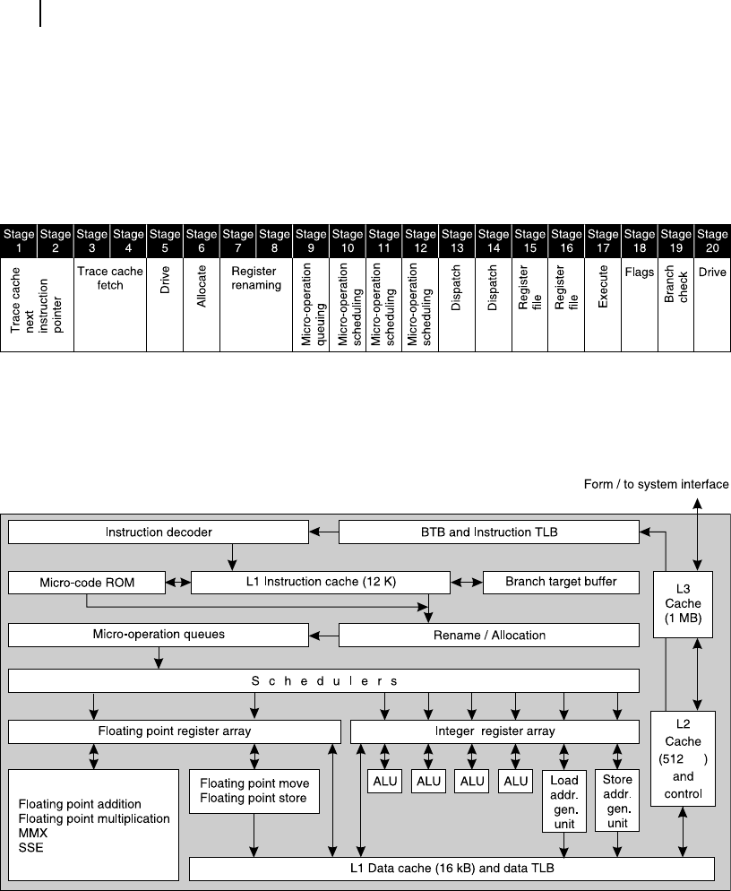
Figure 12.12 Stages of Pentium 4 pipeline
To help the reader to follow the stages of P4 pipeline, we reproduce in Figure 12.13 the simpli ed
schematic of Pentium 4 internal architecture again, the same diagram that we have referred in Chapter 5.
Figure 12.13 Schematic of simplified internal architecture of Pentium 4
kB
The pipeline execution of Pentium 4 starts with the close association with its branch prediction
mechanism. First two stages, indicated as Trace Cache Next Instruction Pointer , takes the help of a 4-bit
branch prediction mechanism (Section 12.5.2 and Figure 12.9 ) and the branch target buffer (BTB) and
selects appropriate instructions when branching instructions are encountered.
M12_GHOS1557_01_SE_C12.indd 386M12_GHOS1557_01_SE_C12.indd 386 4/29/11 5:24 PM4/29/11 5:24 PM
..................Content has been hidden....................
You can't read the all page of ebook, please click here login for view all page.