
422 Computer Architecture and Organization
The rst two, i.e., power-on reset and external reset are available in all processors. The third one,
watch-dog reset, is generated by WDT, which we are about to discuss. The fourth one, brown-out reset,
is activated when the power supply falls below a preset level. This fall of input voltage, generating the
brown-out reset, has to be used for implementing necessary actions from the processor. ATmega8 allows
the programmer to know the source of the last reset (one of four) through one of its I/O registers, marked
as MCUCSR, by using its least signi cant four bits.
We have discussed about some of the architectural features of ATmega8, taking it as an example case
of microcontrollers – the heart of embedded systems. All major architectural issues of microcontrollers
are taken into account in this discussion. However, there are many minor details, which vary from one
microcontroller to another, and it has to be studied in a case-by-case basis. Let us now discuss some of
the organizational issues related to our example microcontroller, ATmega8.
14.5 ORGANIZATIONAL ISSUES
In Chapter 1 (refer section 1.1.1), we have indicated the difference between computer architecture and
computer organization. Although it was mentioned there that computer architecture deals with planning
for larger modules while organization deals with their implementation through electronic detailing –
their demarcation line sometimes becomes fuzzy. In other words, in architecture and organization there
are several grey areas.
As the reader can understand easily, the organizational details for a microcontroller, like ATmega8,
would be enormous to be discussed completely within the available scope of this book. However, a few
salient features of it are presented to the reader to get some ideas about it.
14.5.1 DC Characteristics of Port Pins
One of the important features of any microcontroller is its current sourcing and sinking capabilities
through its I/O pins. In general, the sourcing limit of any port pin is much less than its sinking capabili-
ties. To enhance this current sourcing limit, external buffers or drivers are to be used by the designer.
Another method to solve this issue is to use the logic low as the active logic to communicate with the
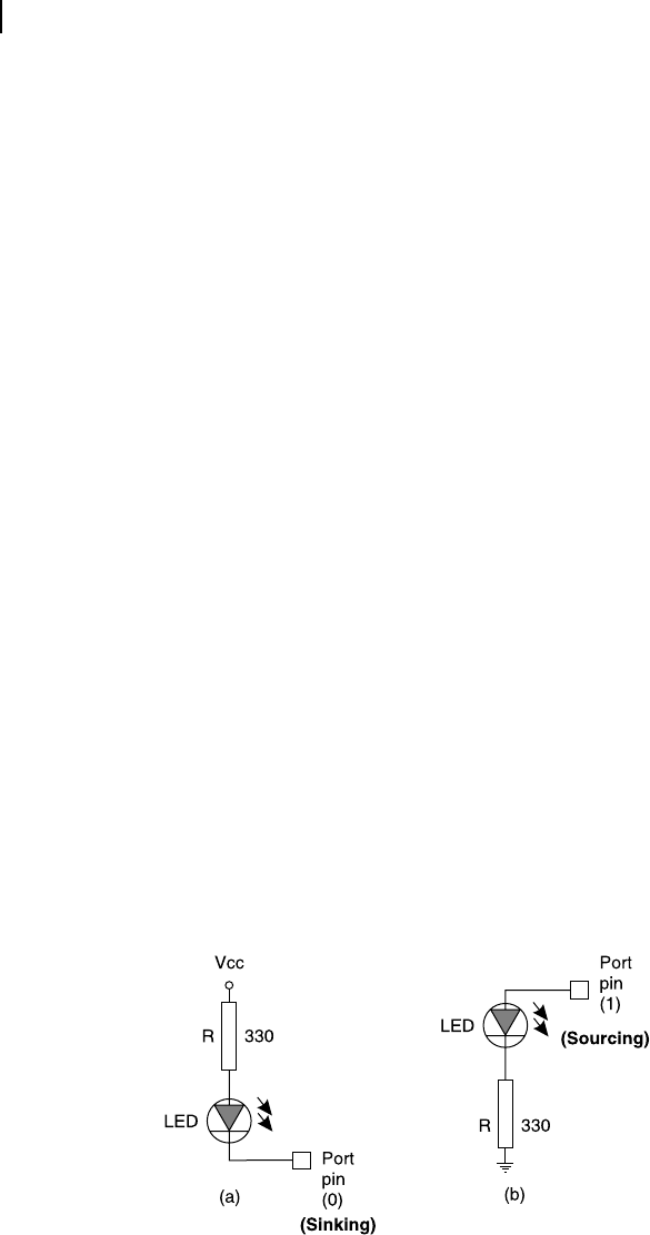
external unit. We may take the case of a LED to be driven by a port pin. As in general, it needs about
5 mA current to turn on a LED, which is beyond the source limit of general port pins (we get about
400 μA in these cases as the upper limit of current sourcing), the LED must be interfaced in such a man-
ner that a logic low turns it on, as indicated in Figure 14.9 (a).
Figure 14.9 Activating a LED by (a) sinking and (b) sourcing current
M14_GHOS1557_01_SE_C14.indd 422M14_GHOS1557_01_SE_C14.indd 422 4/29/11 5:28 PM4/29/11 5:28 PM
..................Content has been hidden....................
You can't read the all page of ebook, please click here login for view all page.