
454 Computer Architecture and Organization
The instruction grouping logic performs proper grouping of instructions to be placed for execution.
In this case, a balance is maintained between loading the oating point unit and integer operation unit
so that none is overloaded while the other is free or idle. The load store unit contains the L1 data cache
and maintains two queues for loading and storing data. It was already indicated that both L1 instruction
cache as well as L1 data cache are of 16 kB each. The data cache is a direct mapped cache and uses
write-through technique to pass on the written data to the next higher cache, i.e., L2 cache and the main
memory simultaneously. We have already discussed in Chapter 7 that in write-through technique, the
data is immediately written in all locations and, therefore, the modi cation is immediate. The instruc-
tion cache (L1) is a two-way set associative cache (Chapter 7) and capable of handling four instructions
in a single cycle.
The pre-fetch/dispatch module has a branch-prediction unit inside it and using two-bit branch-
prediction algorithm (Chapter 12) is capable of targeting proper instructions with minimum amount
of cache-miss. This enables UltraSPARC to allow a smoother operation within its nine-stage pipeline,
which we are about to discuss next.
B.6 PIPELINING
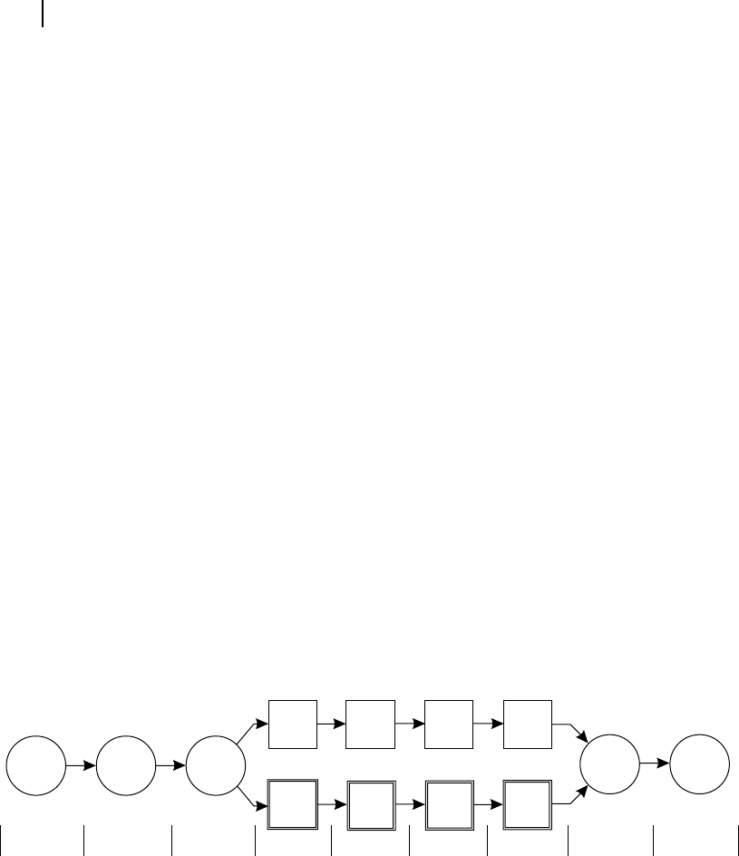
It may be observed from Figure B.4 , that UltraSPARC has a nine-stage pipeline for its superscalar
operation. As indicated in the diagram, from Stage 4 to Stage 7, the pipeline bifurcates into two dif-
ferent paths related with oating point and normal integer operations, and meets again at Stage 8. The
reader may note that the oating point operation also includes the image-related operations using visual-
instructions, while the normal integer operation also includes other non-ALU operations.
The rst stage is opcode fetch for which the processor simply looks into the L1 instruction cache
and grabs four instructions at a time in one cycle. Note that, in case of UltraSPARC, four instructions
consumes 16 bytes of memory, or takes half-a-line in L1 instruction cache. All UltraSPARC instructions
consume 4 bytes uniformly, another basic characteristics of any RISC architecture. The next stage is the
instruction decoding stage and after that the instructions are deposited within the 12-entry instruction
queue, to be treated by the grouping logic unit.
Figure B.4 Nine-stage pipeline of UltraSPARC
Execute
Register
Cache
Z1
P1
Z2 Z3
P2
Stage 1 Stage 2 Stage 3 Stage 4 Stage 5 Stage 6 Stage 7 Stage 8 Stage 9
Fetch Decode Group
P3 Write
The third stage is taken care of by the grouping logic unit whose duty is to pick up next four instruc-
tions from a pool of 12 instructions (within the instruction queue) so that a balanced utilization of inte-
ger ALU pair and oating point ALU pair is maintained. The reader may refer Figure B.3 for these four
ALUs within UltraSPARC.
After the grouping action, the pipeline bifurcates to integer (and other similar) operation and oating
point (and image-related) operation. Within the integer pipeline, Stage 4 executes most of the instructions
Z02_GHOS1557_01_SE_C17_App_B.indd 454Z02_GHOS1557_01_SE_C17_App_B.indd 454 4/29/11 5:40 PM4/29/11 5:40 PM
..................Content has been hidden....................
You can't read the all page of ebook, please click here login for view all page.