

Power PC 465
32 kB. In the rst and most of the versions, L1 cache is 8-way set associative. However, for version 603,
it was 2-way and for version 604, it was 4-way set associative.
The L2 cache was available from version G3 and, before that, Power PC architecture was modi ed
from 32-bit to 64-bit, maintaining the backward compatibility. The initial size of L2 cache varied from
256 kB to 1 MB. However, in version G5 we observe that it was xed at 512 kB. L2 cache is 2-way
set associative. In its G5 version, Power PC supports external L3 cache for a maximum size of 1 MB.
Version L1 Cache L2 Cache Remarks
601 U 32 kB – 32-bit
603 I 16 kB
D 16 kB
– 32-bit
604 I 32 kB
D 32 kB
– 32-bit
With advanced super-scalar design
740 (G3) I 32 kB
D 32 kB
256 kB –1 MB 64-bit
G4 I 32 kB
D 32 kB
256 kB –1 MB 64-bit
G5 I 64 kB
D 32 kB
512 kB 64-bit
Table C.1 Cache memory for different versions of Power PC
As illustrated through Figure C.1 , Power PC offers two integer processing ALUs and two oating point
processing ALUs, each set with its dedicated register array. After fetching and decoding, separate issue
queues are lled with appropriate instructions to keep all ALUs of the processor busy. Power PC has a
dedicated branch prediction unit, the details of which we shall discuss at a later stage in this appendix.
C.4 REGISTER SET OF POWER PC
User-accessible registers of Power PC may be classi ed into three groups ( Figure C.2 ), namely
R Fixed point registers
R Floating point registers
R Branch processing registers
As we may observe from Figure C.2 , apart from a few 32-bit registers, all remaining registers are
64-bit wide.
Both oating point register set as well as xed point register set are composed of 32 general purpose
64-bit registers. For oating point register array, these are identi ed as FPR0 – FPR-31, while for xed
point register array they are referred as R0 – R31. Apart from 32 general purpose registers, the oating
point register array also has a Floating Point Status and Control Register (FPSCR), which is 32-bit wide.
The duty of this register is to accommodate several bit-wide instructions for ongoing oating point opera-
tion and store some indications arising from the result of the ongoing oating point operation. The xed
point register array also has a 32-bit register Exception Register (XER), which has a byte count eld,
useful for string-related operations and three more bits to indicate the exceptions related to ongoing xed
Z03_GHOS1557_01_SE_C18_App_C.indd 465Z03_GHOS1557_01_SE_C18_App_C.indd 465 4/29/11 5:42 PM4/29/11 5:42 PM
466 Computer Architecture and Organization
point operation. All general purpose registers of xed point register array may be used to hold operands
and results and also the indirect address as per the demand of the instructions. Register R0 of xed point
register array indicates zero for some load, store and add operations, irrespective of its present content.
The branch processing unit offers three user-accessible registers, namely Link, Count and Condi-
tion. The rst two are 64-bit while the last one is of 32-bit only. The link register has to be used to
have the address of the next executable instruction immediately after a conditional branch instruction
to help the control in returning to the main stream for execution. The count register has to be utilized to
count the number of iterations for any loop or to hold some address for indirect addressing. The condi-
tion register contains eight condition codes (from CR0 to CR7) each of 4-bit or one nibble.
Figure C.2 Some important registers of Power PC
FPR0
FPR1
FPR30
FPR31
Floating point registers
31
63
0
0
FPSCR
R0
R1
R30
R31
Fixed point registers
31
63
0
0
XER
Link
Count
Branch processing registers
63
0
0
Condition
31
Details of the condition register is shown in Figure C.3 . Note that all condition nibbles from CR0 to
CR7 are available for any compare instruction to check and decide the further course of action. How-
ever, CR0 is reserved for integer instructions and CR1 for oating point instructions. All four bits of
CR0 are set, if carry bit (Rc) is set for any integer operation. Similarly, all four bits of CR1 is set, if a
carry is produced by any oating point operation.
Figure C.3 Details of condition register of Power PC
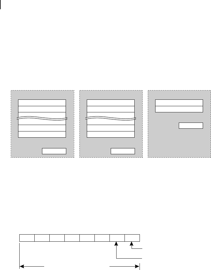
31 28 27 24 23 20 19 16 15 12 11 8 7 4 3 0
CR7 CR6 CR5 CR4 CR3 CR2 CR1 CR0
For integer instructions
For floating point instructions
For all compare instructions
Figure C.4 illustrates the details of XER register of Power PC. As already indicated, most signi cant seven
bits of this register is used for byte count for any load/store operation, when some speci c number of bytes
are written or read related to some string operation. Least signi cant three bits of this register contains three
special ags, namely SO, OV and CA, re ecting the summary over ow, over ow and carry, respectively.
Note the difference between SO and OV bits, as in one case (for SO) the bit, if set, it would be cleared by
the software, while in the other case (for OV) it would be automatically cleared by the execution of the next
instruction. Power PC also offers a Machine State Register (MSR). This register is useful for responding to
any eventual interrupts. In the case of a super-scalar machine, apart from the register contents and ag status,
various control conditions also have to be saved for future use, in the case of such interrupts. In this case, the
MSR helps us as all relevant machine status are readily available within this register.
Z03_GHOS1557_01_SE_C18_App_C.indd 466Z03_GHOS1557_01_SE_C18_App_C.indd 466 4/29/11 5:42 PM4/29/11 5:42 PM
..................Content has been hidden....................
You can't read the all page of ebook, please click here login for view all page.