
Power PC 467
C.5 POWER PC INSTRUCTION SET
The instruction set of Power PC may be classi ed to six major types, namely
R Load/Store
R Integer arithmetic
R Floating point
R Logical and Shift
R Branch oriented
R Cache management
Instruction format for all versions of Power PC is of 32-bit, irrespective of the data bus width of the
version, which may be either 32-bit or 64-bit, depending upon the version. Group-wise the mnemonics
and major function of these instructions are presented through Tables C.2 – C.7 . Note that in total, we
may nd 25 mnemonics, one of the major characteristics of any true RISC processor.
Mnemonic Function
lwzu Load word and zero-extend to its left. Also update the source register
ld Load a double word (64-bit)
lmw Load multiple word
lswx Starting from a given register, load a string of bytes
Table C.2 Load/Store instructions
Table C.2 presents load and store instructions of Power PC. Note that only through this group of
instructions Power PC may communicate with the memory. For all arithmetic and logical operations,
including oating point operations, operations are allowed only through registers. The load/store instruc-
tions are capable of handling byte, half word, word and double word data, apart from string information.
If directed, then the left side of any loaded data may be lled with zero or the sign bit of the number.
Mnemonic Function
add Add operands within two registers and store the result in a third register
subf Subtract one register content from another and store result in a third register
mullw Multiply low order 32-bit of two registers and store 64-bit result in a third register
divd Divide two 64-bit register and store quotient in a third register
Table C.3 Integer arithmetic instructions
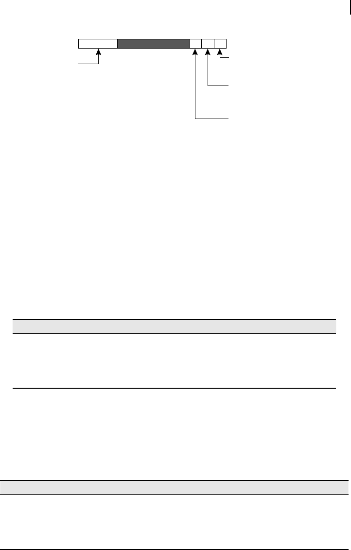
Figure C.4 Details of fixed point exception register (XER) of Power PC
31
Byte count
CA 0V S0
25 2 1 0
Summary overflow–set as 1
to indicate any overflow,
to be cleared by software if set.
Overflow–set to 1 to indicate any
overflow during execution of any
instruction and cleared by next
instruction if no overflow.
Carry–set to indicate carry out of MSB
Specifies number of bytes
to be transferred by load/
store string indexed instruction
Z03_GHOS1557_01_SE_C18_App_C.indd 467Z03_GHOS1557_01_SE_C18_App_C.indd 467 4/29/11 5:42 PM4/29/11 5:42 PM

468 Computer Architecture and Organization
Instructions for integer oriented arithmetic operations are shown in Table C.3 , which includes four
basic operations of arithmetic, addition, subtraction, multiplication and division with integer operands.
Note that for all instructions three register format is supported, i.e.,
R 1 ← R2 + R3
shown related with addition operation only. The multiply instruction generates a 64-bit product of two
32-bit integers.
The oating point instructions (Table C.4), on the other hand, support addition and multiplication
apart from loading and comparing oating numbers. It may be noted that apart from load and store
instructions, lfs is the only instruction, which interacts with the memory exclusively for oating point
data loading. Another special instruction is the fmadd instruction, which multiplies two oating point
numbers in two registers and then add the product with a third register to place the nal result in a fourth
register, e.g.,
R 1 ← (R2 × R3) + R4
The last instruction of this group compares two oating point numbers and the result is re ected
through ags.
Mnemonic Function
lfs Load 32-bit oating point number from memory, convert it to 64-bit format and then store in indi-
cated oating point register
fadd Add content of two registers and store result in a third register
fmadd Multiply contents of two registers, add the result with a third register and place the nal result in
a fourth register
fcmpu Compare two oating point registers and re ect the result of comparison through condition ags
Table C.4 Floating point instructions
The next group of instruction mnemonics, i.e., logical and shift instructions are presented in Table C.5
along with their functional descriptions. Both bit-wise as well as word-wise logical ANDing instructions
are provided along with the standard shift, rotate and compare instructions. For the shifting operation, the
shifted out bits are placed within an indicated destination register.
Mnemonic Function
cmp Compare two operands and adjust four condition bits in the speci ed eld of the condition register
crand Two indicated bits of the condition register are ANDed and the result is placed in one of the two
bit positions
and Logically AND content of two registers and place the result in a third register
cntlzd Starting from bit 0, count number of 0 bits in a source register and place the number of count in
a destination register
rldic Rotate left 64-bit register, AND with mask and store result in a destination register
sld Shift left bits in source register and store shifted bits in destination register
Table C.5 Logical and shift instructions
Z03_GHOS1557_01_SE_C18_App_C.indd 468Z03_GHOS1557_01_SE_C18_App_C.indd 468 4/29/11 5:42 PM4/29/11 5:42 PM

Power PC 469
All branch-oriented instructions are shown in Table C.6 , which offer both conditional as well as
unconditional branching directives. For conditional branching, three different conditions of the indi-
cated bit are taken into account. These three conditions are
R Branch if the bit is zero.
R Branch if the bit is non-zero.
R Branch irrespective of the bit condition (‘don’t care’).
If the count register has to be tested for zero or non-zero condition, then it is decremented by one
before the condition testing, which helps in the iteration process.
The address of the instruction immediately following the branch instruction is also indicated and
might be placed within the link register to help the control for call/return operations.
Mnemonic Function
b Branch unconditional
bl Branch to the target address and place effective address of the instruction immediately following
the branch instruction within the likn register
bc Branch conditional as per count register and/or as per bit in condition register
sc System call to evoke an operating system service
trap Compare two operands and invoke the system trap handler if speci ed conditions are found to
be true
Table C.6 Branch oriented instructions
Two instructions related with cache memory handling are presented in Table C.7 .
Mnemonic Function
dcbf Data cache block ush. Perform look up in cache on speci ed target address and perform
ushing operation
icbi Instruction cache block invalidate
Table C.7 Cache management instructions
If we compare instruction set of Power PC with that of UltraSPARC, then we find that the
number of instructions of Power PC is considerably less as compared with the number of
instructions of UltraSPARC. The same would be the observation, if we compare with instruc-
tion set of MIPS R4000 (in Appendix-E). Therefore, Power PC may be taken as an example of
having minimum number of instructions among most RISC processors.
F
O
O
D
F
O
R
T
H
O
U
G
H
T
Z03_GHOS1557_01_SE_C18_App_C.indd 469Z03_GHOS1557_01_SE_C18_App_C.indd 469 4/29/11 5:42 PM4/29/11 5:42 PM
..................Content has been hidden....................
You can't read the all page of ebook, please click here login for view all page.