

520 Computer Architecture and Organization
28. A 16-bit CISC processor is to offer two modes of operations, normal and reduced . In reduced mode of
operation it uses only lower eight bits of the data bus. All 16 bits of the data bus are used in normal mode.
Assuming all instruction opcodes of the processor are of 16-bit, design the microarchitecture of the
processor. Assume that normal and reduced modes are selectable by an external hardware input signal.
P A R T – C
1. Design a 4-bit ALU to implement following eight functions:
R Add with carry
R Subtract with carry
R Increment by one
R Decrement by one
R Logical AND
R Logical OR
R Logical XOR
R Logical NOT
Assume that apart from carry input, two 4-bit inputs A(0 – 3) and B(0 – 3) are available along with three
select lines. Increment by one, decrement by one and logical NOT may be performed with B input only.
2. Design the hardware circuit of a multiplexed display using four 7-segment display units. The dis-
play units may be of common cathode type and their cathodes may be controlled by suitable transis-
tors driven by a decoder, whose input may be obtained from a binary counter. To drive the anodes,
a driver like 74245 may be used which may be interfaced with a small RAM.
3. A microprocessor like 8085 with 16 address lines and eight data lines is to have the following
memory map. Assuming that 4 kB, 8 kB and 16 kB ROM and RAM ICs are available with you;
design the decoding circuit for the memory interfacing.
FFFFH
0000H
4 KB RAM
or ROM
4 KB RAM
or ROM
16 kB RAM
8 kB RAM
4 kB RAM
4 kB ROM
8 kB ROM
16 kB ROM
4. Using logic gates, construct a clocked SR ip- op on a breadboard. Now verify its truth table.
5. Using ip- ops and logic gates, construct a 4-bit shift register on a breadboard. Now verify its
functioning.
Z06_GHOS1557_01_SE_C21_App_F.indd 520Z06_GHOS1557_01_SE_C21_App_F.indd 520 4/29/11 5:47 PM4/29/11 5:47 PM
Project Bank 521
6. Arrange 16 tactile keys in a 4 ⫻ 4 matrix. Connect these keys as in the circuit shown below. Use a
2 to 4 decoder to activate any one of four columns at a time. Drive the decoder by a binary counter.
Now prepare a circuit using the scan lines and return lines in such a manner that any key pressed
would turn on only one of sixteen indicator LEDs.
Scan lines
Return lines
7. Design a circuit with two keys and two LEDs for indicating who presses a key faster than the other
in the who’s fi rst game.
8. A small system is to use ordinary cassette recorder to store les in serial format. Design a suitable
le format and necessary hardware interfacing to implement it.
9. Assume that the le format and related hardware are already designed by you, generate the neces-
sary owcharts to store and load a le. Note that during loading there may be multiple les to select
one le from them. Assume that every le would be provided with a unique le number.
10. Design necessary hardware and related software so that a processor based system is able to store its
present value of program counter and stack pointer in a permanent storage device (eg. A tape drive)
in case of any unforeseen power failure.
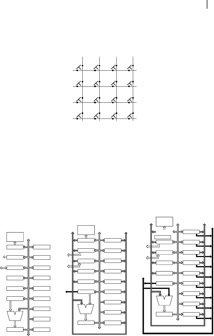
11. The diagram below shows one-bus, two-bus and three-bus systems for three different processors.
Find out the number of cycles to respond against any external interrupt for these three systems and
then make a comparative study of it.
To/From External
memory
To/From External
memory
IR R0
R1
R2
R3
R4
R5
R6
R7
C-Bus
C-Bus
B-Bus
A-Bus
B-Bus
ALU
A
MAR
MBR
PC
SP
Y
Z
Control
unit
Control
unit
IR R0
R1
R2
R3
R4
R5
R6
R7
ALU
A
MAR
MBR
PC
SP
Y
Z
To/From External
memory
C-Bus
Control
unit
IR R0
R1
R2
R3
R4
R5
R6
R7
ALU
A
MAR
MBR
PC
SP
Y
Z
Z06_GHOS1557_01_SE_C21_App_F.indd 521Z06_GHOS1557_01_SE_C21_App_F.indd 521 4/29/11 5:48 PM4/29/11 5:48 PM
..................Content has been hidden....................
You can't read the all page of ebook, please click here login for view all page.