
Computer Arithmetic 77
To start the rst cycle, a left-shift of 1-bit is performed with RQ locations jointly. This produces 1111
in R and 0110 in Q as a 0 is inserted at the LS bit of Q. At this stage, the sign of location V and sign of
location R are same, R is replaced by R − V, i.e., 0001. As the old sign of R is changed by this subtrac-
tion, R is restored to its original value of 1111. C is decremented from 4 to 3, to complete the rst cycle.
The second cycle begins with one-bit left-shift of RQ jointly, inserting a 0 at LS bit of Q. This
transforms R to 1110 and Q to 1100, generating identical signs for R and V locations. Therefore, R is
replaced by R − V, which would be 0000 in this case. As the previous sign of R is changed by this sub-
traction at this point, R must be restored to its original value before subtraction (but after the left-shift),
which makes R as 1110 again. Location C is then decremented to 2 and we may enter in the third cycle.
The left-shift of RQ locations at the starting of third cycle makes R as 1101 and Q as 1000, as a 0
is inserted at LS bit of Q. At this point, we compare R with V and conclude that they are of same sign,
demanding a replacement of R by the value R − V. This changes R to 1111 maintaining the previous sign
of R unchanged. This is because the sign of R has not changed by subtraction, we have to set the LS
bit of Q as 1, which makes Q as 1001. We then decrement C by one, to make it 1 to end the third cycle.
The fourth and nal cycle starts with one-bit left-shift of RQ locations keeping R as 1111 and chang-
ing Q to 0010. As R and V have same signs, R is replaced by R − V, i.e., 0001. The change of sign of
R forces us to bring back R to its previous value of 1111. Location C is decremented to 0 at this point,
indicating the end of the division operation. Location Q holds the quotient, i.e., 0010 or decimal 2.
R holds the remainder in form of 1111, i.e., −1 in decimal when expressed in two’s complement form,
agreeing with the correct answer.
4.7 FLOATING-POINT NUMBER REPRESENTATION
So far we have restricted our discussions within the integer range. However, considering reality, we nd
that decimal arithmetic demands the usage of fractional numbers also. This is the reason for expressing
various decimal numbers by incorporating a decimal point, which we designate as real numbers to dif-
ferentiate from integers.
4.7.1 Signed-magnitude Representation
One straight-forward method is to express the integer (before the decimal point) part and fractional (after
the decimal point) part in two different locations, leaving aside one-bit as the sign bit for the integer part.
For the sake of example, let us assume that we are using 8-bit system. We leave aside the most signi cant
bit as sign bit. The next three bits are used to express the integer part. The last four bits are used to represent
the fractional part. Schematically, this is shown in Figure 4.19 (a), using +6.4 as an example case.
In this example case of representation, we nd that the non-fractional part, occupying bits 4, 5 and 6
can accommodate any value between 0 and 7. On the other hand, the fractional part, represented by least
signi cant four bits (0 to 3) can show any value between 0 and 9. Why is it so? This is because, although
with 4 bits we can accommodate a range of 0 to 15, however, for decimal representation, it falls short.
Either we should show between 0 and 9 (one place after decimal) or we must accommodate between 0
and 99 (two places after decimal). As with four bits we cannot accommodate beyond 15, therefore, we
restrict our fractional representation within one place after decimal.
Therefore, the maximum positive and negative number that we may express using this scheme would
be +7.9 and −7.9 (in the last case the sign bit would have 1). The smallest positive number we may repre-
sent would be +0.1 and the smallest negative number would be −0.1. As usual, for the signed-magnitude
scheme, we have two representations of zero, namely +0 and −0 [Figure 4.19 (c)]. In Figure 4.19 (b),
M04_GHOS1557_01_SE_C04.indd 77M04_GHOS1557_01_SE_C04.indd 77 4/29/11 5:04 PM4/29/11 5:04 PM

78 Computer Architecture and Organization
Figure 4.19 Representation of real numbers
graphical representation of this range and the distribution of numbers are presented. As we may observe,
within the available range of +7.9 to −7.9, real numbers may be correctly represented at an interval of 0.1.
However, this method of real number representation generates a problem, as discussed below.
4.7.2 Solved Example 4.7
What would be the range and accuracy of real numbers that may be represented by 16-bit system, using
signed-magnitude representation scheme? Let us assume the most signi cant bit for sign indication,
next 7 bits for integer part and least signi cant 8 bits for holding the fraction part.
With 7 bits, the integer part can express a maximum integer of 127. For the fractional part, 8 bits would be
able to accommodate a maximum of 255 from zero. However, as it does not permit to cover the maximum
range of three places after decimal, i.e., 999, the maximum fractional part may be considered up to 99, which
uses 7 bits. Therefore, the maximum possible real number in this system would be +127.99 and the minimum
would be −127.99. The expressible numbers would be accurate up to two places after decimal, i.e., 0.01.
4.7.3 Scientific Representation
In the application of computers, we nd a very wide range of real numbers to be covered. For example, in
cosmology, distances are expressed in light years and that number too would be enormous to express the
distances between far and near galaxies. On the other hand, in areas like quantum mechanics, extremely
small values are expressed, e.g., the diameter of a proton. Smaller numbers may also be generated during
processing of larger numbers, e.g., in case of divisions. If we have to establish a common platform be-
tween this inter-galactic distance and size of sub-atomic particles, then, we have to nd a method to do so.
If we have to extend the range of both integer as well as the fractional part of the expressible numbers,
then, we may do so by incorporating more bits in our signed-magnitude representation scheme. However,
this method of representation of decimal numbers (real numbers) is not an optimum one. Why do we say so?
This is because, using the same number of bits, the present range may be extended to a larger limit. For that
purpose we should use another method of real number representation, generally known as scientifi c nota-
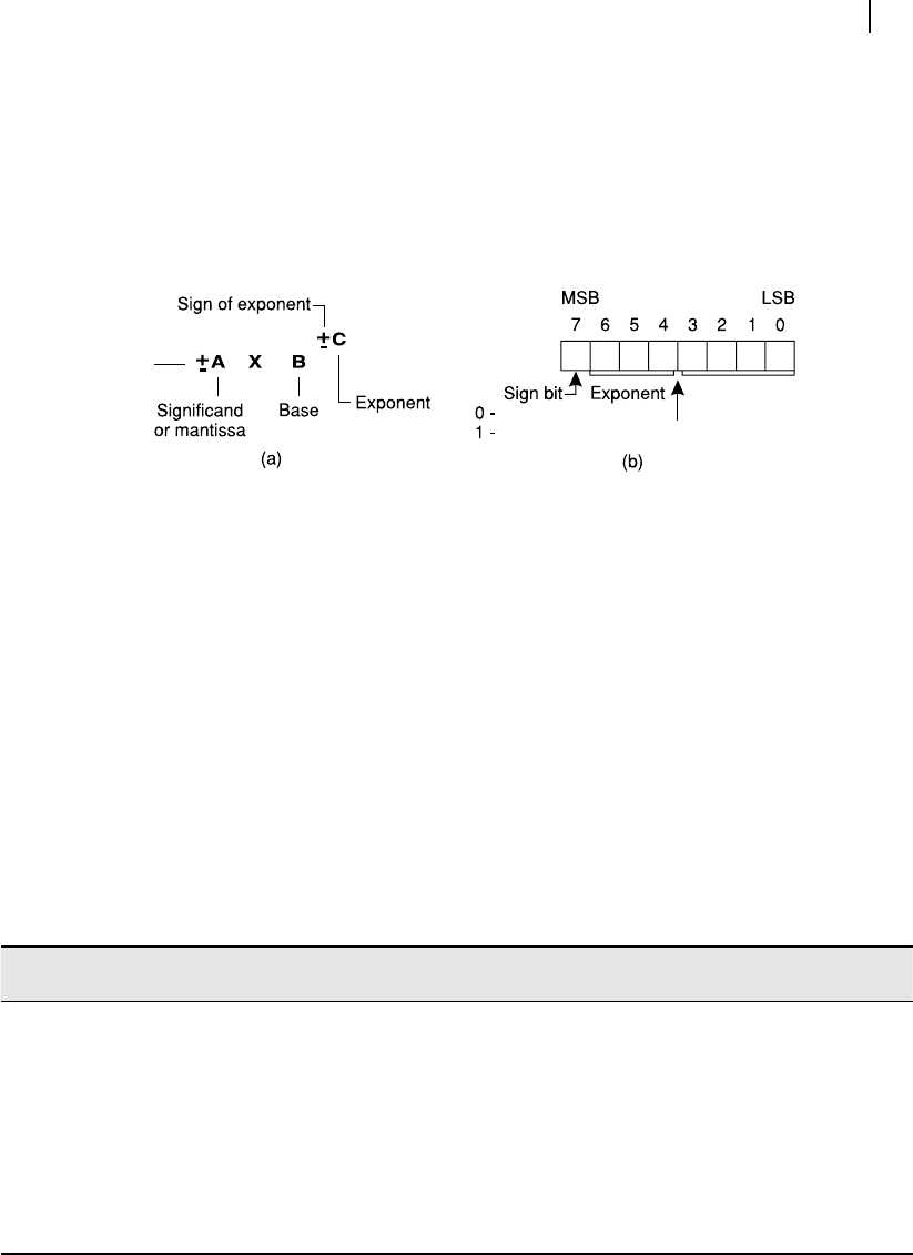
tion or exponential form . The general structure for this representation scheme is shown in Figure 4.20 (a).
M04_GHOS1557_01_SE_C04.indd 78M04_GHOS1557_01_SE_C04.indd 78 4/29/11 5:04 PM4/29/11 5:04 PM
Computer Arithmetic 79
Note that in this scheme, we assume the base (B) to be a prede ned integer (may be 2 or 10 in deci-
mal). However, once it is nalized, then it need not be incorporated within our representation scheme as
it is implicit in that case. The reader may wonder why it may be selected as 2 and why not always 10.
We shall observe shortly that by selecting the base as 2, we may gain certain advantages. Therefore, for
the purpose of storage we have to use a sign bit for the mantissa (or signi cand) and then reserve a few
bits for the mantissa (A) itself. Next, we have to store the exponent part (C) itself. Using the previous
8-bit format, the scheme would look as represented in Figure 4.20 (b).
4.7.4 Biasing the Exponent
At this stage, by comparing Figures 4.20(a) and 4.20(b), the reader may wonder what had happened to
the sign bit of the exponent C? The sign bit indicated in Figure 4.20 (b) is the sign of the number itself
or the sign of mantissa, as we may designate it. As a matter of fact, we would store the exponent in
two’s complement form, which eliminates the need of a separate sign bit. Furthermore, we shall bias
the exponent after computing its value in two’s complement form. Why should we bias the exponent?
This is because we shall be able to accommodate the whole range of it between positive maximum and
negative maximum. We clarify it further by referring to Table 4.3.
As we have decided for our example case to restrict the exponent within three bits, we shall con-
sider the same 3-bit representation here, which may later be extended to any number of bits. As we can
express all decimal values between 0 and 7 using 3-bit representation, they are shown in rst two col-
umns of Table 4.3. Note that these are all positive numbers.
Figure 4.20 Scientific notation scheme
Positive
Binary point
Significand
Negative
Sign
Positive
decimal Binary
Negative
decimal
Two’s
complement
Biased
decimal
Biased binary
(2’s complement)
0 000 0 000 −4 100
1 001 −1 111 −3 101
2 010 −2110−2110
3011−3 101 −1 111
4 100 −4 100 0 000
5 101 −5 011 1 001
6110−6 010 2 010
7 111 −7 001 3 011
Table 4.3 3-bit biased two’s complement
M04_GHOS1557_01_SE_C04.indd 79M04_GHOS1557_01_SE_C04.indd 79 4/29/11 5:04 PM4/29/11 5:04 PM
80 Computer Architecture and Organization
On the other hand, if we are interested about the negative range from 0 to −7, we may easily get those
by generating two’s complement of the binary representations of the second column of Table 4.3. These
are presented in column 4, along with their corresponding decimal representations in column 3. Therefore,
using any one of this scheme, we may represent either between 0 and 7 or between 0 and −7.
However, neither 0 to 7 nor 0 to −7 would give us a desired balanced range, which would be between
−4 and +3 in our case (considering 3-bit representation). Therefore, to generate this, we may add −4
with each row of column 1 to convert or bias those numbers between −4 and 3, as presented in column 5
of Table 4.3. Binary representations of these decimal numbers are present in the next column, i.e., col-
umn 6 of Table 4.3. Therefore, the purpose of biasing is to get a balanced set of numbers on either side
of zero or the origin. We shall refer these last two columns of Table 4.3 in the subsequent discussions.
4.7.5 Normalizing the Mantissa
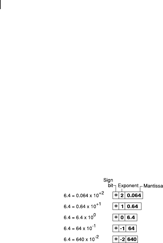
When we express a real number in the scienti c notation format shown in Figure 4.20 (a), it may take
different shapes. To explain this matter, let us assume that we are using a base of 10 (decimal), as we
are more accustomed with decimal representation. Figure 4.21 indicates ve different ways in which
we may express a real number 6.4 (taken as an example case). At the extreme end, within the boxes,
the way it may be stored using our format, is indicated. In this case, to standardize the representation,
we may adopt a rule, that the decimal point for mantissa would be appearing after the rst digit, for any
number. In that case, the standard representation for our example number would be +0 6.4, as shown in
the middle row of Figure 4.21 . This is known as normalizing.
Figure 4.21 Different way of expressing the same value in scientific notation
However, when we adopt the binary system, instead of decimal system, the decimal point has to be
replaced by the binary point . What is a binary point? The binary point is exactly like a decimal point, i.e.,
the digits at its right are taken as fractions (less than one). In decimal number system, if we place a digit, say
7, just at the right of a decimal point, we know that it is representing one-tenth (10
−1
) of seven. If we write
0.07 then we are trying to express one-hundredth (10
−2
) of seven and so on. The binary point also works
in an identical fashion. If we place a 1 just at the right of a binary point, it is expressing 2
−1
or 1/2 or 0.5 in
decimal. Another 1 next to it (at its right) would denote 2
−2
, i.e., 1/4 or 0.25 in decimal. Figure 4.22 may
be used to refresh our memory regarding the positional values in binary system along with a binary point.
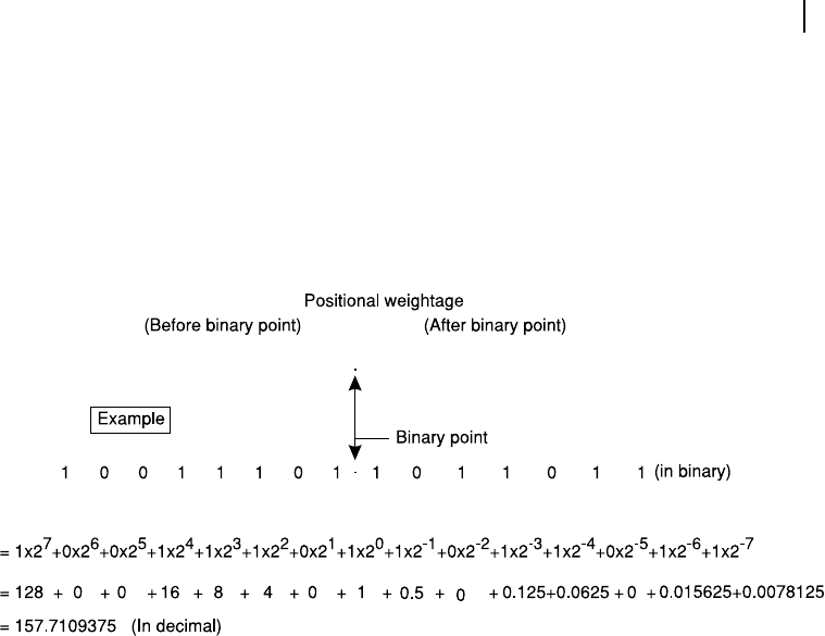
Figure 4.22 (a) shows the positional weightage of binary digits placed at left as well as right of the
binary point. As we may observe that the digits at the right of binary point express fractions and the
more we proceed towards the right, the more they are decreased uniformly. As we use the base 2, these
weightages (after binary point) may be expressed as 1/2, 1/4, 1/8 and so on.
M04_GHOS1557_01_SE_C04.indd 80M04_GHOS1557_01_SE_C04.indd 80 4/29/11 5:04 PM4/29/11 5:04 PM
Computer Arithmetic 81
As an example case, Figure 4.22 (b) shows a binary number where we nd a binary digit at its middle.
Using our positional code, depicted in Figure 4.22 (a), this binary number (10011101.1011011) may be
converted to its decimal equivalent, which comes out to be 157.7109375. In this case, another point
may be mentioned that by adding 0s at the left of any binary integer does not change its value, similarly,
placing 0s at the right of binary digits placed after the binary point does not make any difference and
may be ignored. That means, 11.11 in binary and 11.1100 in binary are same, just like, 11.11 in binary
and 0011.11 in binary are taken as identical expressions.
Figure 4.22 Binary point and positional values
2
7
(a)
(b)
2
6
2
5
2
4
2
3
2
2
2
1
2
0
2
-1
2
-2
2
-3
2
-4
2
-5
2
-6
2
-7
Continuing our discussions on normalization, if we represent binary numbers in fraction, they also
need to be normalized in identical fashion, using scienti c notation scheme. In this case also, we allow
only one digit at left of binary point and the exponent may be adjusted accordingly. In other words, 11.1
(in binary) has to be modi ed to 1.11 and the exponent part must be adjusted for it. For decimal numbers,
we are accustomed with this adjustment. However, for binary numbers, the method is identical. Let us
take an example that is illustrated in Figure 4.23.
In this example, we assume a binary number with 11.1 as its mantissa and 2 as its exponent. There-
fore, in scienti c notation, the number may be expressed as 11.1 × 2
1
. In our storage format it would
appear as 1 11.1, without considering its sign bit and assuming it to be a positive number. Note that we
have added the binary point in our storage format representation only for clarity and it would not appear
in the storage. If we expand the scienti c notation, the value of the number may be obtained as 7.0, as
shown at the right side of Figure 4.23 (a).
Now, for the purpose of normalization, we need to shift the binary point in such a manner that there
is only one digit at the left of the binary point. In other words, in this case, we shift the binary point
one digit left, making the mantissa as 1.11. For this shift the exponent also has to be adjusted and it is
increased by one making it 2 [Figure 4.23 (b)]. Note that for every left-shift of the binary point, the ex-
ponent is to be incremented by one . Similarly, for every right-shift of the binary point, the exponent is to
be decremented by one . One would have observed that we follow the same rule for our decimal number
system also when we adopt the scienti c notation. The absolute value of the number remains same as it
is shown at the right-most side of Figure 4.23 (b).
M04_GHOS1557_01_SE_C04.indd 81M04_GHOS1557_01_SE_C04.indd 81 4/29/11 5:04 PM4/29/11 5:04 PM
..................Content has been hidden....................
You can't read the all page of ebook, please click here login for view all page.