
Instruction Set and Assembly Language Programming 161
The advantage of this method of locating a data is that if the same table has to be used multiple times
to access multiple entries, then the index register need to be loaded only once. In 8051, instruction set
MOVC A, @A+DPTR
may be taken as an example of indexed addressing mode.
Figure 6.8 illustrates an example of indexed addressing mode, assuming R
n
to be an index register
of the processor. In this case, the offset of the target address is indicated as 7, which is added with the
content of R
n
to get the target address of the data to be copied in R1.
6.5 INSTRUCTION FORMATS AND FIELDS
As we have already discussed, the nal form of executable instruction would be in machine language
with Boolean representation of all instructions. This representation of instruction is known as opcode
for the processor. These opcodes may need only one byte or multiple bytes of space to generate a com-
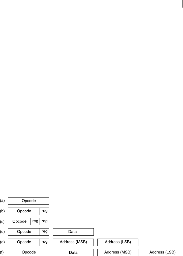
plete description of the instruction ( Figure 6.9 ). To put it in another way, every opcode must inform the
processor clearly and explicitly what to do. The format of these opcodes varies with the instruction type.
For example, an instruction may not need any operand (instructions like: RETURN or RET). This type
of instruction may occupy only one byte [Figure 6.9 (a)]. On the other hand, an instruction with immedi-
ate addressing mode may need two bytes, the rst one may contain the opcode itself and the destination
register’s identi cation and the second one might be the immediate data byte to be loaded within that
register (Figure 6.9 (d)). Schematically, a few variations of opcode formats are presented through Figure
6.9 . Note that the exact format is dependent upon the processor and its instruction set.
In Figure 6.9 (b) the instruction and a register’s code are included within one byte. Any one register
oriented operation, like: increment the register content by one , may adopt this format. Figure 6.9 (c) indi-
cates another widely adopted format, mostly used to copy a data byte from one register to another. In this
case both source register as well as destination register’s name are included within the instruction format.
In direct addressing mode of data loading to a register, the process may use the format shown
in Figure 6.9 (e). In this case, a complete 16-bit address forms the part of the instruction format,
consuming its second and third bytes. The rst byte accommodates the instruction along with
the indication of the destination register. Note that the order of the MSB and LSB of the address
Figure 6.9 Schematic of a few formats of instructions
may interchange, depending upon the processor. In some processors, MSB comes rst (in the sec-
ond byte of instruction) followed by LSB. In some other processor, the LSB might be placed rst
followed by MSB.
M06_GHOS1557_01_SE_C06.indd 161M06_GHOS1557_01_SE_C06.indd 161 4/29/11 5:09 PM4/29/11 5:09 PM
162 Computer Architecture and Organization
When some immediate data need to be loaded in any directly addressed location, a four-byte format,
as shown in Figure 6.9(f), may be useful. In this case, the rst byte contains the instruction, second byte
the immediate data, and remaining two bytes specify the target address.
6.5.1 Role of Processor
To nalize the instruction format, the architecture of the concerned processor plays an important role.
For an 8-bit processor (with 8-bit data bus), instructions would be necessary to load 8-bit data. In major-
ity of such cases, provision to handle 16-bit data also needs to be incorporated. In some cases, bit or
nibble (4 bits) handling provisions also may not be ruled out.
Furthermore, the number of available registers within the processor would intervene in the instruc-
tion formatting. If the number of on-chip registers is more, larger number of data bits must be assigned
In 8051 instruction set, loading an immediate data to a directly addressed memory location
consumes three instead of 4 bytes. This is because the maximum addressable internal data
memory space for 8051 is addressable by 8 address lines and not sixteen.
F
O
O
D
F
O
R
T
H
O
U
G
H
T
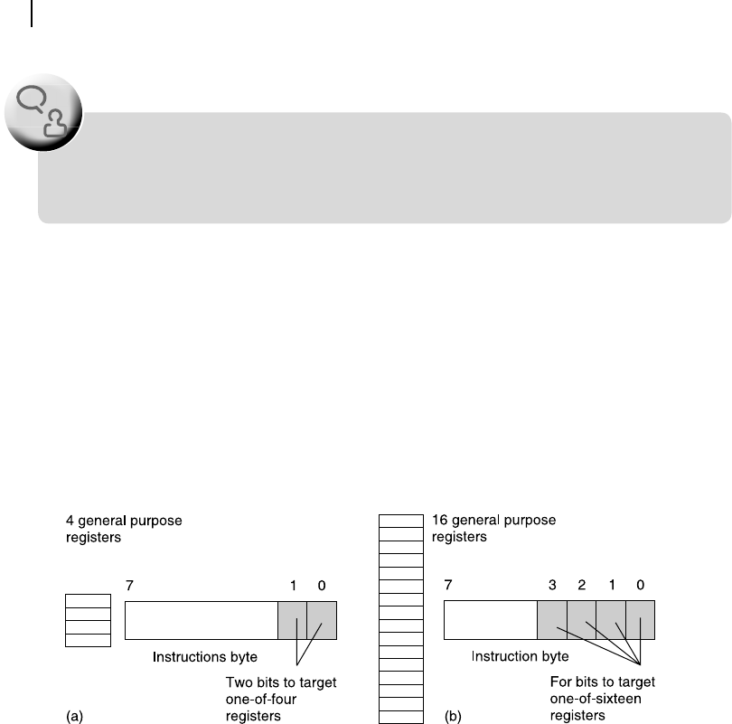
Figure 6.10 Register field variation for processor with (a) four and (b) sixteen
registers
to target one of these registers by decoding the encoded register-addressing bits. In other words, the
width of the register eld within the instruction code (opcode) would increase.
This is illustrated through Figure 6.10 showing two cases of different processors, one with four and
the other with sixteen general purpose registers. As indicated in Figure 6.10 (a), the processor with four
registers has to reserve only two bits of its opcode to accommodate its register eld. On the other hand,
for the processor with sixteen registers, four bits of its opcode has to be left aside as register eld, as
shown in Figure 6.10 (b).
6.5.2 Role of Instruction Set
The instruction set itself plays an important role to nalize the instruction format. If the number of instruc-
tions is more (such as a CISC processor), then more bits are necessary to encode the instruction. On the
M06_GHOS1557_01_SE_C06.indd 162M06_GHOS1557_01_SE_C06.indd 162 4/29/11 5:09 PM4/29/11 5:09 PM
..................Content has been hidden....................
You can't read the all page of ebook, please click here login for view all page.