

The Memory System 209
presently occupying certain area of cache. The way this correlation is maintained is known as mapping .
In general, one of the following three methods is used for mapping.
R Direct mapped cache
R Set associative cache
R Fully associative cache
7.4.9 Direct Mapped Cache
To explain the basic working principle of direct mapped cache, let us imagine a very small computer,
whose main memory (8K) and cache (64 bytes) are shown in Figure 7.5 . Note that we are using a very
small amount of main memory and cache memory, just for the sake of explanation of details.
Let us assume that our imaginary processor has 13 address lines and 8 data lines capable of directly
addressing 8 kB of memory. For the convenience of data handling, let us assume that this 8 kB is
equally divided into 128 pages, so that each page is composed of 64 bytes. Each page is divided into
8 sets, each with 8 bytes. Each set is composed of 4 lines and each line is made up of 2 bytes.
Therefore, assuming for both cache as well as main memory
R 2 bytes form one line (Figure 7.5 (a)
R 4 lines form one set (Figure 7.5 (b)
R 8 sets form one page (Figure 7.5 (c)
R 128 pages form a complete main memory [Figure 7.5 (e)].
In the direct mapped cache, the cache size should be equal to one page of main memory, which is
64 bytes in our example case. This is shown in Figure 7.5 (d).
Figure 7.5 Example schematic for direct mapped cache
The basic principles of direct mapped cache are
R The size of cache must be equal to the size of page
R Any line number copied from main memory to cache memory must occupy the same line num-
ber of cache memory.
M07_GHOS1557_01_SE_C07.indd 209M07_GHOS1557_01_SE_C07.indd 209 4/29/11 5:12 PM4/29/11 5:12 PM
210 Computer Architecture and Organization
Note that there are a total of 32 lines in our cache and the same number of lines is present in each
page of main memory. Therefore, for example, if we copy line 7 of page 4 of main memory, it must be
placed in line 7 of cache memory. Similarly, if we copy line 7 of page 120 of main memory, that must
also be placed in line 7 of cache memory. Note that whenever the main memory has to be copied to
cache, it must be copied line-wise, i.e., two bytes at a time.
We should now have an imaginary cache controller, to be placed between the processor and cache,
as shown in Figure 7.4 . This cache controller must have its cache directory inside it. In this example
case, our imaginary cache controller is having 12-bit cache directory or TAG-RAM. We now discuss the
details about the entry in this tag-ram.
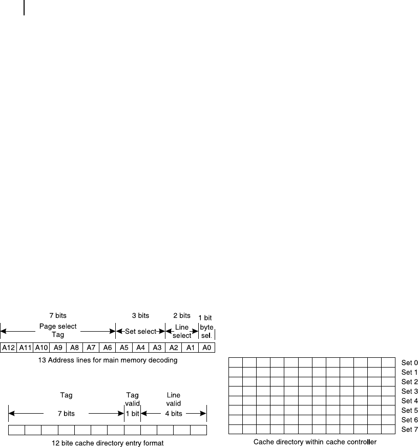
We may visualize the usage of 13-bit address of the processor in the following way for memory decod-
ing. Referring Figure 7.5 (e), we may say that the highest seven bits of memory address (A12-A6) may be
used to select one of 128 pages of main memory. The next three address bits (A5-A3) may be used to select
one out of eight sets within the target page. The next two bits (A2 and A1) would be helping in selecting
one out of four lines of the selected set within the target page. Whenever a line is selected, two consecutive
bytes pertaining to that line would be sent to the processor and the cache through its controller. This usage
of processor’s address to select different elds is pictorially presented through Figure 7.6 (a).
Our cache directory of our imaginary cache controller is 12-bit. Eight of such 12-bit locations are
available within the cache directory [Figure 7.6 (c)]. Out of these 12 bits, the highest seven bits are
reserved for TAG bits. The next one bit is TAG-valid bit. The subsequent four bits are line valid bits
[Figure 7.6 (b)]. Let us assume 1 indicates valid and 0 indicates invalid. Note that this 12-bit format
represents all four lines of a particular set and there are a total of eight such sets in a page of 64 bytes of
the main memory. Now let us see how this mechanism works.
Figure 7.6 Cache directory entry details for cache controller in example case
(a)
(
b
)(
c
)
Whenever the processor needs a line (it is always a line and never a single byte), it sends out its address
with A0 as 0. This address is rst captured by the cache controller. Using A5 − A3 of the address eld, it
targets its own cache directory line (representing that set) and for that selected line of directory entry, it
compares its upper seven bits (tag bits) with the highest seven bits of the captured address. If it matches,
then it checks the tag-valid bit of that set. If it is 1 (tag is valid), then it reads one of the four line repre-
senting bits by decoding A2 and A1 of captured address. If the concerned line-valid bit is set, the line is
already available within the cache (cache hit) and the address is passed to the cache and its data are sent to
the processor. If there is a mismatch in tag-bits or tag-valid bit is 0 or line-valid bit is 0, then it is a case of
M07_GHOS1557_01_SE_C07.indd 210M07_GHOS1557_01_SE_C07.indd 210 4/29/11 5:12 PM4/29/11 5:12 PM
The Memory System 211
cache miss. In that case, a complete address is sent to the main memory controller, which reads the main
memory and releases its data. This data are sent to processor and also stored within the cache and the cache
directory is properly updated for future use. Note that A5 – A1 of address bits [Figure 7.6 (a)] are sent to
cache memory to store the new line at its correct location. A5 − A3 are used to target the entry of cache
directory and A2 − A1 are used to target the line-representing bit of cache directory, for updating it.
If the processor offers the cache facility, like Intel 80486, then the cache controller is a part of the
processor and the designer need not worry about the hardware interfacing. At the most some initializa-
tion commands are necessary to organize the in-built cache controller. However, for processors like
8086 or 80386, external cache controller, like 82385, would be necessary to be interfaced with the pro-
cessor. The salient points regarding direct mapped cache are presented below.
R The main memory to be divided into few pages, pages to be divided into several sets and each
set is to be composed of several lines. Generally, a line contains multiple bytes.
R During main memory transactions, always one line would be transacted. Depending upon the
processor, the line may have one or multiple bytes.
R The size of cache should be equal to the size of any one page of main memory.
R When any line is copied from main memory to cache memory, the storage line number in cache
must be the same line number as that of main memory.
R Every set is represented by one entry in cache directory with its least signi cant bits represent-
ing concerned line numbers.
R The page addressing part of the released address from processor is the TAG-address.
R Set addressing part of target address (released from processor) is used to target the correct entry
point of cache directory.
R Both TAG-address including the tag-valid bit as well as the line number must be matched within
cache directory for a cache-hit.
We now solve a few examples to be more familiar with direct mapping technique.
7.4.10 Solved Examples
Problem 7.1
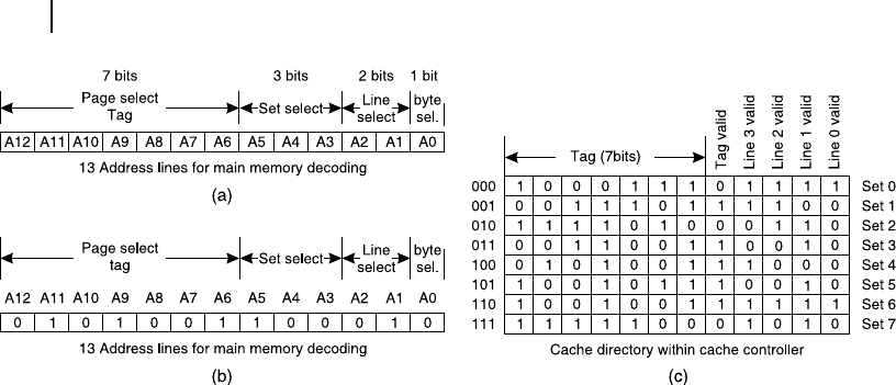
In the same imaginary hardware con guration as explained through Figures 7.5 and 7.6 , assuming the
processor has sent out the 13-bit address of 1 0010 1110 1011B [ Figure 7.7 (a)] for the rst time and
another 13-bit address of 0 1010 0110 0010B [Figure 7.7 (b)] for the second time and the present condi-
tion of cache directory (TAG-RAM) is as shown in Figure 7.7 (c), identify whether these two are cases
of cache-hit or cache-miss.
Solution
In the rst case, the 13-bit address from the processor is 1 0010 1110 1011B, as shown in Figure 7.7 (a).
In the scheme,
Tag address is A12-A6, that is 1001011
Set select bits are A5-A3, that is 101 (set 5), and
Line select bits are A2-A1, which are 01, that is line number 1.
From Figure 7.7 (c), we observe that the current entry at set 5 of cache directory is 1001 0111 0010B.
Its most signi cant seven bits are tag bits, which are 1001 011B, which matches perfectly with the
M07_GHOS1557_01_SE_C07.indd 211M07_GHOS1557_01_SE_C07.indd 211 4/29/11 5:12 PM4/29/11 5:12 PM
212 Computer Architecture and Organization
most signi cant seven bits of the processor’s address. The tag-valid bit of set 5 within cache direc-
tory (tag RAM) is set as 1 indicating the entry is valid. Out of four line valid bits of set 5 of tag-RAM,
line 1’s bit is set, indicating that line is presently available in cache. Therefore, it is a case of cache-hit.
In the second case, the 13-bit address from the processor is 0 1010 0110 0010B, as shown in Figure 7.7 (b).
In the scheme,
Tag address is A12-A6, that is 0101001
Set select bits are A5-A3, that is 100 (set 4), and
Line select bits are A2-A1, which are 01, that is line number 1.
From Figure 7.7 (c), we observe that the current entry at set 4 of cache directory is 010100111000B.
Its most signi cant seven bits are tag bits, which are 0101001B, which matches perfectly with the most
signi cant seven bits of the processor’s address. The tag-valid bit of set 4 within cache directory (tag
RAM) is set as 1 indicating the entry is valid. Out of the four line valid bits of set 4 of tag-RAM, line
3’s bit is set, indicating that line is presently available in cache. As it is line 1, which is being searched
by the processor as per the available address from it, it is a case of cache-miss.
Problem 7.2
Assume that for a computer with 8085 CPU, we have to interface a direct mapped cache memory and
a cache controller. Assume that 8085 is interfaced with 64 kB of memory through 16 address lines and
8 data lines. This 64 kB is divided into 128 pages of 512 bytes each. Each page is sub-divided to 64 sets
of 8 lines each. Each line is composed of only one byte. Calculate the size of cache and the width and
size of cache directory necessary for the system.
Solution
As each page of main memory is of the size of 512 bytes, the same would be the size of cache, i.e., 512 bytes.
Out of 16 address lines from 8085, least signi cant three bits (A2 – A0) would be used to target any
line (1 out of 8). To target 1 of 64 sets within any page 8085 would use six address lines (A8 – A3).
Therefore, remaining seven most signi cant address bits (A15 – A9) would be used to target any one of
available 128 pages of main memory.
Figure 7.7 Schematic for Solved Example 7.1
M07_GHOS1557_01_SE_C07.indd 212M07_GHOS1557_01_SE_C07.indd 212 4/29/11 5:12 PM4/29/11 5:12 PM

The Memory System 213
The cache directory must offer 64 rows, one each for possible 64 sets. In each row, most signi cant
seven bits would be used as tag-address. There would be one bit as the tag-valid bit. To indicate validity
of 8 lines of the set, there must be another 8-bits within the same row in cache directory. Therefore,
every row of cache directory would need 16-bits. Therefore, the width of cache directory would be
16-bits and it must contain 64 rows.
Problem 7.3
In an 8086 based system, 8 kB of direct mapped cache is interfaced using some cache controller. Every
line of main memory contains two bytes and every set contains 16 lines. Calculate how many rows are
required for the cache directory in its tag-RAM?
Solution
In direct mapped cache directory, the number of rows of cache directory would be equal to the number
of sets within every page of main memory. This page size of main memory must be the same as the page
size of cache memory that is 8 kB. As every set contains 16 lines and every line is composed of two
bytes, the number of sets in any page is
8 × 1024 / (16 × 2) = 256
Therefore, 256 rows are required for the cache directory in its tag-RAM.
7.4.11 Set Associative Cache
One major disadvantage of direct mapping technique is that any line of cache has to represent that
line of any page of the main memory. For example, if line 7 of page 3 is already within cache and the
processor requires line 7 of page 99, the previously written line 7 of page 3 would be overwritten by
line 7 of page 99. In other words, line 7 of page 3 as well as line 7 of page 99 would not be available
simultaneously to the processor. If it is necessary due to some reason, there would be continuous cache
miss, known as thrashing , and repeated fetching from main memory would be necessary. This problem
may be eliminated by set associative cache.
Set associative cache is generally designed as two-way or four-way. In a two-way set associative
cache, two separate caches of same size as that of a page of main memory are provided. Using the same
main memory con guration as shown in Figure 7.5 , where we have illustrated direct mapped cache, the
cache con guration may be modi ed as presented in Figure 7.8 , if we implement two-way set associa-
tive cache mapping technique.
In this case, there are two pages of cache, each having 64 bytes. The cache directory uses the same
tagging technique, as described for direct mapped cache. However, in this case both caches are searched
one after another. If both are unable to deliver, only then it is a case of cache miss.
It is insisted that reader solves several problems related to cache in own hand to get a quicker
and better understanding of the subject matter.
F
O
O
D
F
O
R
T
H
O
U
G
H
T
M07_GHOS1557_01_SE_C07.indd 213M07_GHOS1557_01_SE_C07.indd 213 4/29/11 5:12 PM4/29/11 5:12 PM
..................Content has been hidden....................
You can't read the all page of ebook, please click here login for view all page.