
18
MULTIPROTOCOL LABEL SWITCHING
18.1 WHY MPLS?
Since its inception, Multiprotocol Label Switching (MPLS) has received a lot of attention in the research community, has been in the headlines in the technical news, and has achieved importance in the marketing strategies of vendors. Noteworthily, MPLS is one of the few examples of networking technology that found the consensus of virtually all vendors of core IP routers, Internet Service Providers, and telecommunications operators, that is, it is the one technology that finally achieves the long sought convergence between the information technology and the telecommunications worlds.
MPLS importance stems from its potential to make IP networks in general and the Internet in particular what have been traditionally called public networks—that is, networks on which operators provide services to be sold. Public networks, domain of the telecommunications world, have been typically providing services with known quality so that they can be the object of contracts between providers and their customers and can be sold for a significant amount of money.
18.1.1 The Onion That Makes Telcos Cry
Mainly due to the success of the Internet with its steady growth and ubiquitous reach, IP has for a long time shown its predominance as the preferred protocol and has more lately become the one protocol on which to base each application. However, network operators have been for many years compelled to deploy several other technologies to implement the services they wanted to sell. This led to the “networking onion” shown in Figure 18.1 where various technologies are deployed in layers to finally support the provision of IP connectivity, as shown by the outer layer. A wavelength division multiplexing (WDM) core is used to (i) maximize the transport capability of each fiber by transmitting over multiple optical channels on the same fiber and (ii) create long haul optical channels across multiple fibers among devices that are not directly connected. This is achieved through the deployment of (i) optical multiplexers and (ii) optical switches, a.k.a. lambda (λ) switches. Although more recently optical channels are being used to connect IP routers directly (as represented in Figure 18.1 by the pipes extending from the WDM core to the IP outer layer) or even customer equipment, most often a circuit-switched network is built on them by means of SDH/SONET multiplexers and switches in order to enable the provision of lower-capacity channels. While the circuit-switching network can be used to sell services—specifically telephony and leased lines—directly to the customers, it does not feature the flexibility required for handling what is traditionally called data traffic. ATM (Asynchronous Transfer Mode) [1] was standardized by ITU-T [2] with the specific goal of realizing a Broadband Integrated Services Digital Network (ISDN)—that is, an infrastructure capable of providing the deterministic quality of service required by traditional telecom applications (such as telephony and videoconferencing) while efficiently supporting data traffic. Packet switching rather than circuit switching was chosen to achieve this goal, as highlighted by the term “asynchronous” that is juxtaposed to the synchronous nature of circuit switching.
Figure 18.1. The “networking onion.”
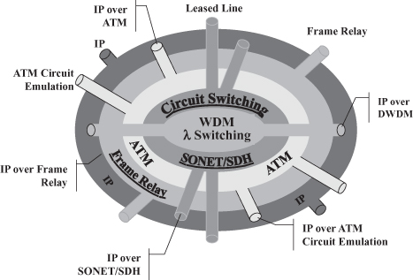
ATM failed to achieve the anticipated success and widespread reach because end users preferred the simplicity and low cost of technologies such as Ethernet and IP to the more sophisticated services of the more costly and complicated ATM. As a consequence, ATM has been confined to the operators’ networks with few customers requiring ATM services (as represented by the pipes extending through the outer layers in Figure 18.1), possibly to interconnect their IP routers, or taking advantage of appealing commercial offers for circuit emulation over the ATM network to interconnect their PBXs (private branch exchanges). Instead, operators resorted to their ATM infrastructure to interconnect their IP routers and provide IP connectivity services.
Although the deployment of an ATM backbone to interconnect IP routers provides some advantages in controlling the traffic and hence the service provided (as discussed later), it is problematic due to the high cost of ATM interfaces on IP routers, which is due to the high complexity of ATM. Consequently, equipment manufacturers designed access devices with Frame Relay [3] interfaces mainly used for the interconnection of IP routers (both the operators’ and the customers’ ones). Frame Relay is a convenient solution for the interconnection of IP routers because, being originally proposed by a consortium of IP router manufactures named the Frame Relay Forum,1 interfaces are available on virtually all high end routers at basically no cost. However, this required operators to add yet another layer to their “networking onion.”
Such a multitude of technologies represents a significant cost for operators that need personnel trained on each of them, gear from several vendors, and spare parts for a large number of devices. Especially as the popularity and ubiquity of IP, further reinforced by the increasing deployment of IP telephony, results in most of the customers requiring IP connectivity services, operators would certainly benefit from getting rid of the “networking onion” in favor of an all IP network—that is, a mesh of IP routers interconnected by optical fibers.
However, controlling the quality of the services offered on such a mesh interconnection of IP routers was until recently very complex, unless the network was engineered so that actual traffic would be a small fraction of the capacity. The sophisticated traffic management support offered by ATM enabled the realization of services with known quality through the ATM backbone while efficiently utilizing its resources. Consequently, commercial IP services have been provided by interconnecting peripheral IP routers through a partial mesh of virtual connections across an ATM backbone.
18.1.2 Enters MPLS
MPLS introduces the opportunity of controlling traffic within
a mesh of interconnected IP routers basically by enhancing IP with a powerful traffic engineering capability. The reason why this is
important, its consequences, and the technological solutions through which this is
realized are discussed in the rest of this chapter. In a nutshell,
MPLS enables IP to work as a connection-oriented protocol while
still retaining the valuable properties of a connectionless one.
This statement, which might sound cryptic and oxymoronic at first, should become clear at the end of the chapter. One key consequence of connection oriented operation is the possibility of facilitating traffic engineering, which is instrumental for an operator to control the quality of the services provided by its network. The way in which MPLS enables traffic engineering and the differences with respect to performing traffic engineering with the connectionless operation of IP are discussed in detail in Section 18.2.5.
By replacing ATM switches with MPLS capable IP routers, the ATM layer can be removed from the “networking onion” in Figure 18.1, and with it the Frame Relay layer can be peeled off as well. After a closer look at the way MPLS uses label switching to forward packets through the network, one might argue that in its basic principles it is not different from ATM. This is true, but the key for MPLS’s popularity as a backbone technology for carrying IP traffic versus ATM’s failure in the same role lies in the former using the same control plane as IP routers, with the latter requiring to operate two different, hard-to-integrate control planes, one for ATM switches and one for IP routers. This concept will be elaborated further in Sections 18.2.4 and 18.4.5.
The distinctive features of MPLS and the widespread adoption of IP to carry voice and telephony enable operators to peel the SONET/SDH layer off the “networking onion” in Figure 18.1. In fact, thanks to the traffic engineering and fast fault restoration capabilities of MPLS operators are able to multiplex and demultiplex IP packet flows on high capacity (2.4 Gbit/s, 10 Gbit/s, 40 Gb/s) optical channels with quality levels that, although lower than SONET/SDH, are suitable to both voice/telephony over IP and IP connectivity services as required by their customers.
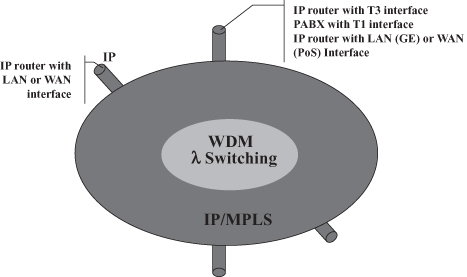
As a result of MPLS deployment, Telcos’ IP-based networks can realize the network architecture graphically represented in Figure 18.2 where a WDM core based on optical switches is deployed to provide connectivity to MPLS-capable IP routers.2 MPLS as a packet switching solution is not expected to replace the WDM core because of the scalability and potential inexpensiveness of (all) optical switching where large volumes of traffic are to be switched along the same route—that is, where the switching of whole optical channels is effective, such as in the very core of the network. However, as briefly discussed in Sections 18.2.4 and 18.5.1, MPLS plays a major role also in the WDM core and its integration with the outer part of the network because the protocols of the MPLS control plane can be adopted as the control plane for the optical network.
Figure 18.2. The future protocol architecture.
Moreover, when introduced, MPLS had an important role in creating new market opportunities for, and fostering competition between, telecommunications equipment vendors and networking equipment vendors. In fact, the former had label switching hardware (from ATM) and know-how in connection oriented technologies and manufacturing of carrier grade equipment (acquired with ATM, Frame Relay, and SONET/SDH), while the latter have competence in running software for the routing and signaling protocols deployed in the MPLS control plane. Consequently, MPLS was seen as an opportunity and endorsed by both classes of vendors, which fostered its importance and sped up its deployment.
18.2 BASIC UNDERLYING IDEA AND OPERATING PRINCIPLES
18.2.1 Label
The basic idea underlying MPLS is to add a label to packets to be used for routing instead of the destination address carried in the IP header. The label was originally added as a means to enable a lookup operation faster than the longest prefix matching required on addresses when routing IP packets (see the origins of MPLS in Section 18.3). As integration technology advanced and router manufactures refined their ASIC (Application Specific Integrated Circuits) design and fabrication skills, IP addresses longest prefix matching became possible at wire speed, thus eliminating the need for a different type of lookup. Consequently, the original label purpose was meaningless, but the importance of another capability enabled by the label became predominant: facilitating traffic engineering. The key MPLS feature in facilitating traffic engineering is the separation of the routing functionality in the control plane from the one in the data plane (see Section 18.2.4), which is made possible by the presence of a label in each packet. This enables network operators to deploy on (MPLS-powered) IP networks the traffic engineering (Section 18.2.5) and fast fault recovery (Section 18.5.2) solutions traditionally deployed in connection-oriented public networks from X.25 to ATM through Frame Relay.
Multiprotocol in the MPLS acronym indicates that the solution was originally targeted not just to IP, but to any routed protocol. However, although some initial developments for AppleTalk took place, today MPLS is being deployed only in conjunction with IP.
18.2.2 Deployment Architecture
Learning from the failure of ATM (which, although expressly engineered to replace all existing networking technologies, has not been widely adopted largely because of its inability to “reach” the desktop dominated by IP), IETF (the Internet Engineering Task Force; see Section 18.3.1) has targeted MPLS to backbone deployment. This way no change is required to end-systems that generate plain IP packets and do not need to be aware of MPLS being used somewhere in the networks on the path of their packets. Labels are used in a limited area, called an MPLS network or MPLS cloud, where label switch routers (LSRs), shown in Figure 18.3, route packets based on their MPLS label. A label is prepended to a packet entering an MPLS cloud by an Ingress LSR and is stripped from the packet upon exiting the MPLS cloud through an Egress LSR. (Due to their position in the network, Ingress and Egress LSRs are also generally called Label Edge Routers.)
Figure 18.3. MPLS deployment architecture.
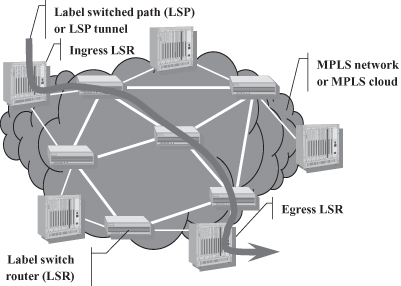
Packets travel across an MPLS cloud over a label switched path (LSP) or LSP tunnel that must have been set up before the forwarding of the packet toward its egress point can begin. From this point of view the LSP resembles a virtual circuit in a connection-oriented network. However, a unique feature of MPLS is that LSP setup does not necessarily require an explicit end-to-end signaling operation, as explained in Section 18.4.3, which enables the MPLS cloud to retain the valuable properties of a connectionless IP network.
18.2.3 Label Switching Operation
Packets are forwarded through the network according to the well-known label switching paradigm that has been deployed for a long time in the history of networking protocols, especially those designed for public networks, such as X.25, Frame Relay, and ATM. Figure 18.4 shows how the label switching paradigm is applied in MPLS networks to realize an LSP. Upon creation of the LSP, an entry is added to the forwarding table of each switch on the path from the ingress LSR to the Egress LSR containing a mapping between the label attached to packets traveling on the LSP when entering the node, the label attached when exiting, and the port through which the packet with the new label shall be forwarded. An LSR, upon receiving an MPLS packet searches the table for the entry whose input label matches the label of the packet, retrieves the new label that replaces the input label in the packet (operation often called label swapping), switches the packet to the output port identified in the relevant table entry, and schedules it for transmission. Changing the label at each hop has the complexity of modifying a packet each time it is forwarded, but it provides the advantage of limiting label validity to each pair of switches.3 In Figure 18.4, label locality is exemplified by the checkered label being used on the first link within the MPSL cloud (i.e., between the Ingress LSR and the first LSR) and on the next-to-last link, but not on the others. Label locality provides higher scalability—that is, the number of bits encoding the label limits the maximum number of LSPs across a link, not across the entire network—and makes label choice when creating an LSP a simple, local matter rather than requiring a distributed agreement on a label unused on all the links traversed by the LSP.
Figure 18.4. LSP working principle: label switching.
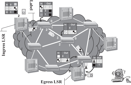
As discussed in more detail in Section 18.2.1, MPLS specifies that in addition to being swapped, a label can be added to or removed from the packet; in Figure 18.4 these operations are performed by the Ingress LSR and the Egress LSR, respectively. The Ingress LSR in the sample scenario depicted in Figure 18.4 receives a plain IP packet (i.e., without a label) and decides what label to attach to the packet based on information contained in the IP header. In the example in Figure 18.4 the label is chosen based on the destination IP address D. According to the MPLS specification, LSRs should be able to route (based on the IP destination address) packets that do not have a label (i.e., traditional IP packets); however, many commercial products do not implement this feature.
A data structure more sophisticated than the forwarding tables shown in Figure 18.5 is used in MPLS switches in order to create a level of indirection between the input label and the output label, rather than a simple table. The purpose is to have multiple input labels mapped to the same output port and label pair, as well as one input label mapped to multiple output port and label pairs. This provides maximum flexibility in the construction of LSPs (e.g., point-to-point, point-to-multipoint, and multipoint-to-point) and their dynamic modification (e.g., for load sharing, overflow, and fast fault protection purposes). The actual data structure supporting the routing operation in MPLS is described in Section 18.4.2.
Figure 18.5. Control and data plane in IP routers.
Looking up a 20-bit label has lower complexity than performing longest prefix matching—that is, finding the entry in the routing table whose destination address has the largest number of bits in common with the destination address in the IP header of the packet being routed. Although initially this was a key advantage of MPLS and the motivation behind its initial design, currently the main benefit stemming from the label is the possibility of controlling the path taken by packets independently of their destination address and the route to it as calculated by dynamic routing protocols, which stems from the network operating according to a connection-oriented paradigm. This enables traffic engineering and fast fault protection, as will be explained later.
However, label-based routing also comes with the disadvantages typical of the connection-oriented paradigm: having to create an LSP and set up forwarding table entries in all the nodes along its path, represents a significant overhead and delay for short, datagram-type communications. Moreover, because packets are routed along a path previously chosen (when creating the connection), connection-oriented protocols lack the adaptability to network faults and conditions that originally inspired the design of the Internet Protocol (IP) and have long been at the core of its success. However, MPLS includes an operation mode (resulting from the combination of independent LSP control and topology-based label binding, presented in Section 18.4.2 and 18.4.3, respectively) in which LSPs are created without the need of explicit end-to-end signaling and as an automatic consequence of route discovery; that is, MPLS has the capability to behave as a connectionless protocol. In other words, an MPLS network can operate according to both the connection-oriented and connectionless paradigms, thus offering the network administrator the flexibility of choosing the one that fits best the needs and requirements of the supported applications and services.
18.2.4 Separation of Control Plane and Data Plane
The distinctive features, whether advantageous or disadvantageous, of the connection-oriented paradigm versus. the connectionless one stem from the different relationship between data plane and control plane each one implies.
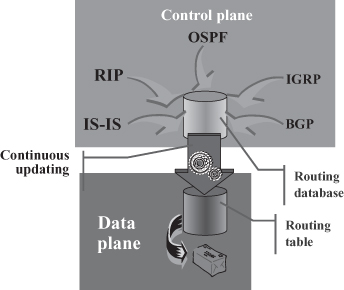
Figure 18.5 shows the relationship between control and data plane in a typical IP router. In the control plane, routing protocols continuously update a routing database, taking into account changes in the topology of the network; a routing table, mapping each destination prefix with its corresponding next hop, is used in the data plane for routing incoming packets and is updated whenever the routing database changes. In other words, a topological change possibly results in an update in the routing table so that whenever a new packet will arrive to one of the input ports of the routes, it will be routed according to the updated information in routing table, thus possibly following a different path to the destination with respect to previous packets if a more convenient route has been found by the continuous update process based on the information gathered by routing protocols. This enables automatic adjustments to topological changes and specifically link and node failures.
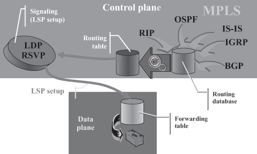
On the other hand, Figure 18.6 shows the functions in the control and data plane of a typical MPLS switch and the relationship among them. A routing table, automatically and dynamically calculated from the routing database continuously updated by routing protocols, is deployed within the control plane by signaling protocols. Whenever an LSP is to be set up, messages are exchanged according to the signaling protocols described in Section 18.4.3 by network nodes along a path determined according to the most recent routing information. Specifically, a node receiving a message requiring the creation of an LSP toward a given destination will use the routing table to establish to which of its neighbors it should send a corresponding LSP setup message. Moreover, as shown by the arrow between the control and data plane in Figure 18.6, the LSP setup procedure results in the installation of a new entry in the forwarding table within the data plane that provides the mapping between a label tagging incoming packets and the next hop to which the packet shall be forwarded (and a new label to be substituted when forwarding the packet, as will be further detailed in Section 18.4). Consequently, the path followed by packets traveling through a given LSP is determined by the corresponding forwarding table entry, which is in turn determined by the dynamic routing information gathered in the routing database at the time of LSP setup. Although such routing database is continuously updated to reflect topology changes, such changes do not impact the forwarding table, hence the path followed by packets of existing LSPs. Consequently, even though the control plane of MPLS switches might be aware of topology changes due to routers or link failures, routing of packets is not adapted accordingly and packets traveling on LSPs through failed network elements are no longer able to reach their destination.
Figure 18.6. Control and data plane in MPLS switches.
As much as such separation between the control and data plane might be a problem, it is a valuable asset to MPLS because it enables the implementation of traffic engineering as discussed in the following section.
18.2.5 Traffic Engineering with and without MPLS
Traffic engineering refers to the action and/or capability of controlling the distribution of traffic across the network with the goal of reaching a given objective, such as (a) keeping link utilization below a certain threshold value or (b) making link utilization uniform. Traffic engineering is key to a network operator to be able to control the quality of the services so that it can abide by the contract with its customers. Moreover, spreading the traffic across the network in a way that no links are underutilized allows the network operator to exploit all the resources (in terms of routers and links) it has invested in to carry customer traffic, thus maximizing the number of customers besides their satisfaction.
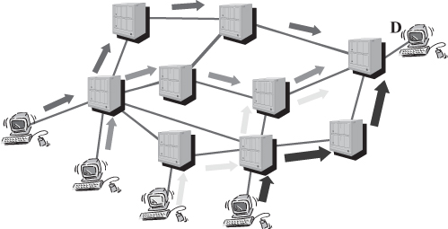
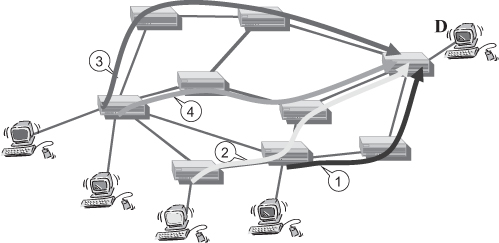
Traditional IP routing does not necessarily pursue the above goals by itself. In fact, traffic routed is based on the destination, that is, packets coming from various sources and going to the same destination tend to be aggregated toward the destination, as graphically exemplified in Figure 18.7. If traffic from each source was uniformly distributed among destinations, link utilization would be uniform. Instead, current Internet traffic is mostly directed toward a relatively small subset of the connected hosts that are servers and major portals offering services to clients around the world. Consequently, traffic tends to aggregate in the vicinity of such preferred destinations and on some links interconnecting autonomous systems containing highly popular sites. In such a situation, graphically represented in Figure 18.7, some of the links turn out to be overloaded, which possibly results in loss, high delay, and ultimately poor performance perceived by customers, while others are underutilized, which implies a waste of resources invested by the network operator. Through a traffic engineering operation, the network administrator could spread the traffic for a given destination (or a group of destinations located in the same topological area) across the network, for example, as exemplified by Figure 18.8.
Figure 18.7. Natural traffic aggregation with destination-based IP routing.
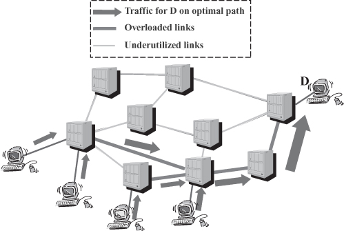
Figure 18.8. Traffic distribution Across the network.
Achieving such a traffic distribution in a network of traditional IP routers is not straightforward. One possible way is by using some sort of static policy routing within routers, that is, make them route packets based on some criteria other than the destination address (alone). For example, the traffic distribution exemplified in Figure 18.8 could be achieved by configuring in each router a static route based on the pair source-destination address. However, in general cases such a solution requires a large amount of configuration work, is prone to errors, and does not react to topological changes in the network, that is, like any other static routing approach manual, intervention is required to overcome node and link failures. Contrary to what it might appear after superficial consideration, traffic aggregation cannot be achieved automatically by using link load as a routing metric. When routers chose routes that involve least-loaded links, traffic begins flowing through such links (for example, some of the links in the top part of the network shown in Figure 18.7), thereby increasing their utilization. As a result, other links become less loaded, routing tables are re-computed, and traffic is re-routed through the newly least loaded link. In the sample network in Figure 18.7, routing will become unstable and keep oscillating between transferring packet through the bottom part of the network and the top part of the network. As a result, the network will be, on average, as congested as in the case of topology-based (i.e., shortest path) routing, but the performance might be lower because routers will spend (a significant) part of their processing power re-computing routing tables over and over, rather than processing incoming packets.
The instability problem stems from the close relation between the control plane and the data plane in IP routers. As updated link utilization information is gathered by the routing protocols in the control plane, routing table entries in the data plane are updated (see Figure 18.5), which affects routing of all subsequently incoming packets. In MPLS, link utilization-based routing can be effectively used thanks to the separation between control and data plane. Routing table updates due to link utilization information changes in the routing database do not affect routing of packets in the data plane because it is based on the forwarding table entries (see Figure 18.6). However, whenever a new LSP will be created, it will be routed according to current information in the routing table and a new entry will be created in the forwarding table of switches along a path involving least-utilized links. Consequently, in the sample network considered in this section, subsequently opened LSPs will be spread across the network, as shown in Figure 18.9, where the number of the LSPs indicates the order in which they have been created and routing chooses the least-loaded path.
Figure 18.9. Traffic engineering with MPLS.
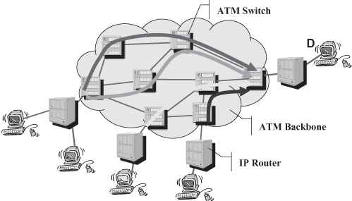
Prior to the availability of MPLS network, operators that wanted to perform traffic engineering on their backbone, would choose a different technology to implement it. For many years the solution of choice has been a backbone based on ATM (Asynchronous Transfer Mode) [1] interconnecting peripheral IP routers, as shown in Figure 18.10, thus reinforcing the onion architecture discussed in Section 18.1.1 (see Figure 18.1) and the issues stemming from it. Moreover, the network architecture depicted in Figure 18.10 raises many problems that were extensively addressed for many years by the vast research and development in the context of internetworking between IP and ATM. The main issues can be summarized as follows:
- IP routers connected to the “ATM cloud” have a large number of adjacencies, that is, all routers connected to the cloud are one-hop neighbors, which affects the number of exchanged message and the amount of computation required by routing protocols, that is, it limits the scalability of the solution;
- IP routers need to know the ATM address of other ATM attached routers in order to be able to forward packets to them.
Figure 18.10. Traffic engineering with ATM.
No satisfactory solution was in fact found before MPLS offered itself as a valid option for the integration of ATM and IP network, as later discussed in Section 18.3.
ATM is from many points of view very similar to MPLS; as a matter of fact, MPLS standard documents specify an ATM “packet format” to be used in MPLS, as presented in Section 18.4.1. Moreover, the MPLS deployment architecture presented in Section 18.2.2 and shown in Figure 18.3 is basically the same as the one depicted in Figure 18.10 for ATM. So, why is MPLS well-integrated with IP—actually, in many cases even presented as a variant of or enhancement to IP, as in Section 18.2.1—while ATM cannot be easily and effectively integrated with IP? The answer—as well as the origin of the two issues listed previously in the internetworking between IP and ATM—lies in ATM switches not being aware of IP routers and vice versa, which, in turn, stems from ATM switches and IP routers not deploying the same control plane. The strength of MPLS in terms of being effectively deployable in IP networks is the adoption of the traditional IP control plane, that is, the same addressing scheme and routing protocols deployed in IP networks. This has certainly played a pivotal role in its technological and market success.
18.3 MPLS HISTORY
The major market and technological success encountered by MPLS stems from it having been multiple times the right solution to a significant problem of the moment, as the short history below highlights.
MPLS originated by Tag Switching a solution originally designed at the end of the 1990s by Cisco Systems [5] to speed up packet forwarding in their routers as part of an effort to build more powerful and scalable devices. Tag Switching was presented in the context of IETF [6], where it gained popularity especially as a solution for the deployment of IP in ATM network. As previously mentioned, there has been a lot of activity around the so-called IP over ATM problem; and among all the various proposals, each with its advantages, but especially disadvantages, Tag Switching stuck out as particularly effective. In fact the basic paradigm underlying Tag Switching was the same as ATM’s—that is, routing based on a label in each packet that is changed at each hop on the way. However, having been conceived as an extension to IP, Tag Switching uses the IP control plane—that is, the same addressing architecture and routing protocols as IP routers, which provided the key to seamless integration between Tag Switches and IP routers. The same basic idea can be applied to solve the IP over ATM problem by including the IP control plane within ATM switches. Given that ATM is a layer 2 technology (with reference to the ISO-OSI layered protocol architecture), while IP is a layer 3 technology, the application of Tag Switching in the context of IP over ATM is categorized as a multilayer switching solution as the data plane works at layer 2 by switching ATM cells, while the control plane works at layer 3 by using IP addresses to identify destination and IP routing protocols to find a path in the network of ATM switches toward them. As was adopted as an IETF solution, the technology was renamed MPLS in order to differentiate from the vendor-specific Tag Switching; notwithstanding the different terminology, the two solutions and their basic components and protocols are the same. Although MPLS popularity began with ATM, it was not over once the latter had failed. On the contrary, once more MPLS was a handy solution to a widespread problem: the death of ATM. In fact, all the players in the ICT domain—that is, telecommunications and computer network equipment manufacturers as well as telecom operators and Internet Service Providers—had invested heavily in ATM throughout most of the 1990s. However, before all these players could get their due return on their investments—the former in the design of ATM equipment, the latter in the deployment of ATM infrastructures—it had become clear that future customers wanted IP connectivity and that the deployment of ATM networks to interconnect IP routers, as exemplified in Figure 18.10, was not effective and led to multilayered infrastructures (see Figure 18.1). MPLS offered a way to convert ATM equipment into IP equipment, or at least IP-aware MPLS equipment, by “replacing” software implementing the ATM control plane with the MPLS one. This could be done in unsold equipment to the benefits of manufacturers and vendors and, at least in principle, on installed one, to the benefit of operators. As a matter of fact, the first MPLS switches were converted ATM switches, which not only enabled manufacturers to recover the investment spent in designing them, but also helped to reduce the time to market for MPLS.
The success and popularity of MPLS continued because once again it was a convenient solution for each of the players of the ICT domain. Operators had a chance to slash their costs by eliminating the onion architecture discussed in Section 18.1.1. IP equipment manufacturers had a chance to provide carrier grade devices suitable to provide reliable and controllable services (once exclusive domain of telecom devices) by equipping their IP routers with MPLS capability, and telecom vendors that had pursued the doomed ATM technology had a chance to enter the growing IP business by evolving their ATM switches into MPLS ones.
The next important milestone in MPLS history was in the early 2000s when optical technologies gained popularity as the means to deliver plentiful bandwidth to all to provide the necessary support to any existing application and open the way to the deployment of many new ones. Notwithstanding the confidence in the advantages of optical networking, partly shaken in the following years, it was by then clear to anyone that applications were going to be based on IP for the time being. Moreover, even though not everyone might have agreed, optical networking was for a while going to be a backbone technology. In other words, optical networks were, at least for some nonnegligible time, to be deployed according to the network architecture shown in Figure 18.10 where the central cloud was a lambda-switched network composed of arbitrarily interconnected optical switches. Such architecture had proven fatal to ATM due to the lack of integration with the external IP routers. Hence, when designing the control plane for the ASON (Automatically Switched Optical Network) [7], it was apparent that being IP-aware was key to success and acceptance. Consequently, ITU-T easily accepted the idea of deploying the MPLS control plane in optical networks, which matured within IETF as MPλS (Multi-Protocol Lambda Switching) [8]. The basic idea is that although data are not switched in the form of IP packets, but as whole optical channels (a.k.a. lambda from the Greek letter commonly used to indicate wavelength), typical IP routing protocols (i.e., OSPF, IS-IS, and BGP), are deployed to find routes to destinations that are identified by IP addresses and MPLS signaling protocols are deployed to create optical path, similarly to the way they are deployed to set up LSPs. While an LSP is uniquely associated with the label deployed to identify and route packets belonging to it, lambdas are uniquely associated to optical channels and deployed to route them into optical switches.
The parallel between MPLS switches routing packets based on a label and optical switches routing bits or optical signals based on a wavelength (lambda)—more specifically the parallel between labels and lambdas as well as between LSPs and optical channels—could be carried even further to any switching device capable of routing data units based on a connection-oriented paradigm. Consequently, as much as MPLS switches use a set of protocols to automatically set up connections (LSPs) along properly computed routes, the same protocols could be used to set up any other type of connections if:
- End systems were identified by means of IP addresses;
- The format of the control messages (i.e., routing and signaling protocols) enabled the system to carry the piece of information corresponding to the MPLS label.
This led to the definition of GMPLS (Generalized MPLS) [9] that, through a generalization of the label concept and a flexible syntax in the control messages, provides a control plane suitable for any switching technology such as packet switching (i.e., MPLS or ATM), circuit switching (e.g., SONET and SDH), optical switching.
This represents the latest reason for the success of MPLS—that is, as a unifying control plane for various technologies whose highly needed integration would otherwise be difficult and inefficient.
18.3.1 Standardization Effort
Various entities produced documents describing MPLS, additional features, and protocols required to implement them. The main actor in the definition of MPLS is undoubtedly the IETF (Internet Engineering Task Force) [10] and more specifically its MPLS Working Group [9] that produced most MPLS-related documents in the form of RFC (request for comments). Although the MPLS Working Group has been chaired by a Cisco Systems’ engineer and people from the manufacturer contributed significantly to various MPLS documents produced, the working group has consisted of individuals working for virtually all major IP and telecom equipment manufacturers.
Another major player in the production of MPLS “standards” has been the MPLS Forum, a consortium of vendors aiming at fostering the deployment of MPLS. Given that the organizations involved in the MPLS Forum were basically the same involved in the MPLS Working Group, in order to avoid duplication of work, the former focused on aspects outside the scope of IETF. For example, given that the IETF considers MPLS as a technology strictly aimed at the network core, the IETF Forum addressed issues related to the deployment of MPLS at the periphery, such as Voice over MPLS (VoMPLS) and MPLS-based ADSL. At some point the MPLS Forum merged with the Frame Relay Forum to form the MPLS/FR Alliance because the same organizations were involved in the two fora and they were tackling similar issues in the same domain; more recently the MPLS/FR Alliance merged with the DSL Forum into the Broadband Forum [4] as one major application for MPLS networks, as it has been for ATM and Frame Relay, is the collection and delivery of traffic generated by DSL modems. Moreover, as discussed in Section 18.4.1, standard documents specify a Frame Relay “packet format” to be used in MPLS, which officially makes frame relay switches a type of MPLS switch.
Because of its suitability to solve enable IP routers to effectively interconnect through an ATM network, MPLS-related documents have been produced also by the ATM Forum, a consortium of companies interested in fostering the adoption of ATM (merged with the MPLS/Frame relay alliance in 2004, which later joined the DSL forum into the Broadband Forum [4]). Given the great importance and wide diffusion of IP, proper interworking between ATM and IP was a very crucial issue to be addressed.
All of the above are not official standardization bodies, but one, the ITU-T (International Telecommunication Union—Telecommunication Standardization Sector) [2], got involved when the MPLS control plane was chosen for the ASON.
Because a significant amount of work on MPLS and related documents was not performed by official standardization bodies, most MPLS specification documents are not standards; however, they are commonly referred as such. If nothing else, MPLS is certainly a defacto standard.
18.4 PROTOCOLS AND FUNCTIONS
MPLS operation requires the specification of three basic protocol elements: (i) a label format and how it can be attached to packets, which led to the specification of an MPLS header format, (ii) mechanisms and protocols required by nodes to handle labels (i.e., signaling protocols), and (iii) routing protocols to determine the route for LSPs, possibly taking into account constraints on the route selection. These three protocol elements together with a few key mechanisms and concepts are the object of this section.
18.4.1 Header Format
MPLS standard documents define a format for the label and how it can be attached to any packet by defining a shim header to be inserted between a generic layer 2 header and a generic layer 3 header [11]. In fact, although MPLS has come to be seen as strictly related to IP—possibly even a variant to IP—originally it was meant to be protocol—independent (from which the “Multi-Protocol” in its name), where the packets carried within the MPLS shim header might be any type of packets, not even necessarily belonging to a layer 3 protocol. For example, in certain current deployments, Ethernet frames are carried on LSPs—that is, within MPLS headers. The remainder of the chapter, when not otherwise relevant, refers to IP packets as carried within MPLS headers.
As shown in Figure 18.11, the shim header consists of one or more modules, each containing a label and other information. The modules are said to realize a label stack as modules can be added (pushed) or removed (popped) only at the beginning (in terms of transmission order) of the sequence. A node receiving a packet processes only the top module—that is, routes the packet based on the label at the top of the stack. This enables the realization of hierarchical LSPs, graphically represented in the left part of Figure 18.12, wherein an LSP identified by a specific value as outermost label includes several LSPs identified by different values for the second label in the stack. Each level of the LSP hierarchy possibly corresponds to a nested MPLS domain, as exemplified in the right part of Figure 18.12. When a packet enters MPLS Domain 1, an ingress LSR inserts a shim header containing Label 1 between the Layer 2 header and the IP packet that will consequently travel on LSP 1 until it reaches a label edge router at the egress of MPLS Domain 1. When on its way the packet reaches the border of MPLS Domain 2, an ingress LSR adds to the shim header a module containing Label 2 so that the packet continues its way to the destination on LSP 2. The Domain 2 LSRs are not aware of the various LSPs within LSP 2 and handle the same way all packets belonging to LSP 2. However, once a packet gets to a Domain 2 egress LSR, the Label 2 module is removed and the packet is handled as belonging to LSP 1—that is, differently from other packets exiting LSP 2 but having a different value in Label 1 (thus traveling on other LSPs through Domain 1). Given the possibility to extend the shim header with further modules, several levels of LSP hierarchy and domain nesting can be realized.
Figure 18.11. Label and shim header format.
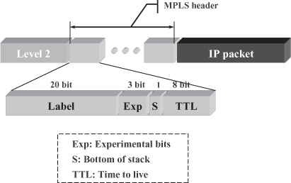
Figure 18.12. Hierarchical LSPs; label stack and nested MPLS domains.
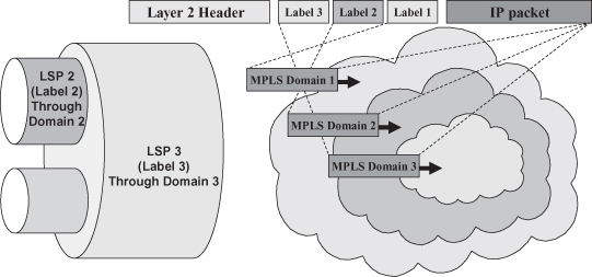
The capability to deploy such a hierarchy of LSPs and MPLS domains has a twofold advantage. Firstly, it enables high scalability because the forwarding tables of the LSRs in the inner domains (possibly part of a high-capacity backbone) include as many entries as the number of LSPs at their hierarchical level, which is much smaller than the total number of end-to-end LSPs (the smaller “pipes” on the left side of Figure 18.12). Secondly, outer domains can set up and tear down LSPs through the inner ones, without the latter being aware of it—that is, in full autonomy. This, besides extending scalability to the control plane, fits to the hierarchical organization of service providers where one provider (e.g., MPLS Domain 1 in Figure 18.12) buys interconnectivity services from a second one (e.g., MPLS Domain 2 in Figure 18.12) to transfer MPLS-enabled IP packets from one of its LSRs to another one. Thanks to the deployment of hierarchical LSPs, once an LSP has been set up between two LSRs of the first service provider through the MPLS Domain of the second one, various LSPs can be autonomously set up and torn down by the first provider’s two LSRs without any involvement of the second service provider’s LSRs. Hierarchical LSPs are instrumental also in other areas of application including virtual private networks and fast fault recovery.4
In addition to the label, which is 20 bit long, each module of the shim header contains the following fields:
- The Exp or experimental field contains three bits whose purpose is not strictly specified in the shim header format document [11], but has been later considered for the realization of Differentiated Services (DiffServ) [12] in MPLS networks [13].
- The TTL or time to live field has the same size (8 bits) and purpose as the homonymous filed in the IP header, namely preventing (temporary) routing loops from bringing (part of) the network to a halt by overloading routers with copies of packets traveling endlessly on circular routes. Each time an MPLS switch routes a packet, is causes decrements in the value in the TTL field of the outermost label module. If the field reaches value 0, the packet is not further forwarded; that is, it is discarded.
- The S or bottom of stack field indicates whether a label module is the one at the bottom of the stack, in which case a switch popping the label knows that it should expect an IP packet, rather than another label module, when parsing the remaining part of the packet.
The encapsulation of the shim header in Ethernet and PPP (Point-to-Point Protocol) frames—that is, the two most deployed layer 2 protocols—is defined in [11] by specifying the value to be used for the ethertype and protocol fields, respectively. Moreover, for proper operation with PPP, an MPLS Control Protocol is defined for MPLS parameter negotiation when a PPP link is initialized.
In addition, the label and MPLS header format specification [11] defines that when the layer 2 protocol in use makes itself use of labels (possibly under a different name, such as virtual circuit identifier or data-link channel identifier), the outermost label shall be carried within the layer 2 header. Specifically,
- When IP packets are carried within ATM cells, the VCI/VPI (virtual circuit identifier/virtual path identifier) fields of the ATM header is used [14];
- When IP packets are carried within Frame Relay frames, the DLCI (data-link connection identifier) in the Frame Relay header is used [15].
Consequently, an MPLS switch upon receiving an IP packet encapsulated in an ATM cell (Frame Relay frame) will route it based on the content of the VPI/VCI (DLCI) field, which is in fact what an ATM switch (Frame Relay switch) does. In other words, the above specifications fully entitle ATM and Frame Relay switches to be considered MPLS switches. The inclusion of the above label encoding options was a very smart decision in the MPLS standardization process because it avoided the fact that ATM or Frame Relay manufacturers would oppose or delay the adoption of technology in order to protect their investment in the legacy technologies. Instead, it provided them with a smooth migration path to MPLS. Moreover, it reduced the time to market for MPLS because networking and telecommunication equipment manufacturers did not need to start the design of MPLS switches from scratch.
18.4.2 Key Concepts
The Forwarding Equivalence Class (FEC) is an important component of the MPLS architecture [16] defined as the set of packets that are forwarded the same way. While in traditional IP packets that receive the same forwarding treatment are those with the same destination address (or prefix thereof), the MPLS FEC can be defined in a more flexible way. In other words a FEC might be identified by any filter on header fields and other information not encoded in the packet (e.g., the port through which a packet is received). Packets belonging to a given FEC are associated with the same MPLS label by an Ingress LSR; and MPLS switches inside the MPLS cloud do not need to reclassify packets to figure out which FEC they belong to, but simply look at the attached label to decide what to do with the packet.
The correspondence between a label and a FEC is called label binding and has to be agreed upon by the two nodes at the ends of the link on which the label binding is used. MPLS specifies that LSRs deploy downstream binding, which implies that a label binding is chosen by the switch at the downstream end of a link—that is, the node that will receive packets with the given label. Bindings can be performed in either an unsolicited way or on-demand—that is, upon an explicit request from the upstream LSR. In MPLS the scope of a label is a single node, i.e., the same label cannot be used for two LSPs traversing the same node. Thanks to the deployment of downstream label binding, the same binding can be used on the links connected to multiple input interfaces, which enables the construction of per-destination delivery trees, which is equivalent to the way routing is performed in traditional IP networks. As a consequence, when LSRs are performing unsolicited topology-base label binding (see Section 18.4.3) with independent LSP control (see below), an MPLS cloud features the same operation and properties of a traditional IP network. Moreover, downstream label binding enables the deployment of LSRs that can operate only with a subset of the possible labels because they just have to bind only labels in the range they can handle.
In any event, once the downstream node has decided a binding between a label and a FEC, it notifies the upstream node, which is referred to as label distribution. MPLS encompasses both ordered and independent LSP control. According to independent LSP control, each LSP independently decides when to make a label binding for a FEC (e.g., upon discovering a given destination) and distribute it. When using ordered LSP control, an LSR performs a label binding for a FEC and distributes it only upon receiving a label binding for the FEC from the next hop to the destination corresponding to the FEC.
A set of protocol has been defined to support label distribution as well as to solicit label binding and are discussed in Section 18.4.4.
Once a node has decided a binding for a given FEC (i.e., for an incoming label) and has received through label distribution by one of its downstream neighbors its label binding (i.e., an outgoing label) for the same FEC, it performs a label mapping by creating in its forwarding table an entry that relates the incoming label with the outgoing label and the port through which the binding had been received. Label mapping results in the actual creation of an LSP, or more precisely a section of it around the LSR performing the mapping.
Actually, MPLS documents [16] define a set of tables to handle label binding and label mapping as shown in Figure 18.13. The Next Hop Label Forwarding Entry (NHLFE) table contains information on outgoing labels, specifically:
- Labels to be used for packets that are being forwarded and whether the label should be swapped, pushed on the stack, or the top label module should be popped.
- The next hop to which a packet should be forwarded.
- Other information that might be useful to handle the packet transmission, such as, for example, the link layer protocol deployed.
Figure 18.13. Label mapping: ILM, STM, and NHLFE tables.
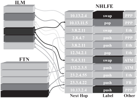
The FEC-To-NHLFE (FTN) table is used to handle label binding in an Ingress LSR: The table contains an entry for each FEC for which the LSR acts as an ingress LSR and each FTN table entry is mapped to one or more NHLFEs. The NHLFE(s) to which an FTN entry is mapped provide the label to be attached to packet (i.e., pushed on the empty label stack) before forwarding the packet.
The Incoming Label Map (ILM) table contains an entry for each label bound by the LSR to a FEC and is used to handle label mapping: Each ILM entry is mapped to one or more NHLFEs, providing the next hop to which incoming packets with the label in the ILM should be forwarded and their outgoing label. When an NHLFE instructs the (egress) LSR to pop the label at the bottom of the stack, the packet being forwarded is a plain IP packet on which the next hop must act as a traditional IP router.
The possibility to map one ILM or FTN table entry to multiple NHLFEs can be used for various purposes, such as multicasting, load sharing, or fast fault protection; the specific use is not specified as part of the basic MPLS architecture [16].
18.4.3 Static and Dynamic Label Binding
Static binding offers the simplest, yet less flexible, way of creating LSPs: By means of a device configuration or management operation, the network administrator associates a label with a FEC in all the LSRs on the path chosen for the packets and creates the corresponding mappings. In other words, the network administrator must create (a) an FTN entry in the ingress LSR(s) and (b) an ILM entry in each LSR on the path, and he/she must map them on the proper NHLFE entries. This solution is equivalent to creating permanent virtual circuits (PVCs) in ATM networks or leased lines in SONET/SDH networks or, in a more general way, configuring static routes in routers; hence it shares their properties and shortcomings. The main advantages of static binding are (i) the network administrator having full control on the way traffic is routed through the network and (ii) network nodes not requiring a control plane. The latter proved convenient, especially in speeding up the commercial release of the first MPLS products. However, static binding has various limitations such as (i) poor scalability, (ii) error proneness due to human mistakes, and (iii) unsuitability to set up LSPs across multiple operators’ networks due to lack of interoperability among different management systems and access rights to network devices.
Dynamic binding offers more flexibility and scalability because LSRs can cooperate to create LSPs in response to a number of different events.
- In data-driven label binding, a new binding is created upon arrival of a packet for which the binding is needed—for example, a packet that does not belong to any of the FECs for which a binding already exists.
- In control-driven label
binding, the triggering event pertains to the control plane:
- According to the topology-based variant, a label binding is created in response to routing information, such as the discovery of a new route by the routing protocols (e.g., OSPF, IS-IS, and BGP).
- According to the explicit event variant, a label binding is created in response to an explicit event, such as a signaling procedure started, for example, by a label edge router or by a network control center. Such an event could be in response to a traffic engineering condition or policy or the detection of a fault in the network.
All of the above dynamic label binding options require protocols for label distribution and possibly event notification, which is the subject of Section 18.4.4. While some of the protocols are suitable to all the dynamic label binding options, others can work only with some of them. Moreover, the choice of which LSRs participate in the label distribution for a given LSP represents a routing decision that determines the path of the LSP and, ultimately, routing of packets belonging to it. Such a decision can be based on routing information either statically configured (i.e., in the case of static routing) or dynamically gathered by routing protocols, which is the subject of Section 18.4.5.
18.4.4 Label Distribution Protocols
Two alternative approaches have been used to support label distribution: (i) adoption of an existing protocol, possibly modified to include new information and functionalities, and (ii) definition of an ad hoc label distribution protocol. The protocols described in Sections 18.4.4.1 and 4.4.2 represent the first approach, while the second one has been followed when defining the Label Distribution Protocol (LDP) discussed in Section 18.4.4.3.
18.4.4.1 Border Gateway Protocol.
The Border Gateway Protocol (BGP) [17] has been designed for interdomain routing in IP networks—that is, to support the exchange of routing information between routers at the border of an autonomous system. Such border routers (or “gateways,” according to the obsolete terminology initially deployed in the Internet) are interconnected to at least one router belonging to a different (neighboring) autonomous system from which they receive quite articulate information about routes to possibly each destination connected through the Internet. Border routers use such information to choose through which of the neighboring autonomous system to forward packets for each destination.
Due to the nature of its application, BGP has two valuable features:
- Packet format has been designed to be customizable and extensible so that new types of information can be easily encoded and exchanged among routers.
- BGP implementations have flexible mechanisms to filter routing information received, transmitted, and deployed in route calculation.
For this reason, BGP is being used also for intradomain routing and in particular is being proposed for routing in MPLS networks. In this case the BGP message format can be extended to carry for each destination, together with the routing information, also the label to be used when sending MPLS packets to the destination. The solution is thus particularly suitable to support topology-based label binding (see Section 18.4.3): an LSR advertising a route to a destination includes in the BGP message also its label binding—that is, the label its neighbors shall use to create an LSP to such a destination. Dually, an LSR receiving a BGP message advertising a route to a destination shall find in the message the label binding used by the neighbor; hence, once the LSR has decided its own label binding and chosen the advertised route to reach the destination, it can create a label mapping for an LSP to such destination.
18.4.4.2 Resource Reservation Protocol.
The Resource Reservation Protocol (RSVP) [18] was introduced in the context of the Integrated Services (IntServ) [19] architecture to provide services with deterministic quality over the Internet. In this context, RSVP is used by hosts to signal to the network the type of service required and its quality (QoS, quality of service) parameters; while relaying RSVP messages between source and destination network nodes can use them to negotiate the amount of resources (e.g., buffer space, output link capacity, processor capacity) needed in each node in order to ensure the required QoS (while messages propagate from source to destination) and to reserve them at each hop on the path (while messages propagate back from destination to source).
Although MPLS at its inception is a routing and transport solution not aiming at addressing QoS issues, it is reasonable to assume that sooner or later it will be a key requirement that packets traveling on an LSP are not only effectively switched to their destination, but also guaranteed a deterministic service. In such a scenario, creating an LSP encompasses, besides finding a route through the network, distributing labels, and installing a label mapping in each node, also requesting a specific service and reserving resources on an LSP. Given that provisioning of services with previously negotiated quality over the Internet is based on the IntServ architecture of which RSVP is the centerpiece, the protocol becomes an attractive solution to enable label distribution and QoS parameter signaling and resource reservation all at once. Consequently, RSVP messages have been extended to include additional information to support both label distribution and traffic engineering (as further detailed in Section 18.4.5.3) resulting in the specification of RSVP-TE (RSVP for Traffic Engineering) [20].
RSVP delators criticize the fact that having been designed for a different purpose, the protocol is not optimized for label distribution and, more in general, signaling in MPLS networks. For example, RSVP has been designed to be a softstate protocol; that is, all information network nodes obtained from RSVP are considered to have limited temporal validity and expire; consequently, in order to be kept valid, it needs to be refreshed by periodic exchanges of RSVP messages. This results in a significant burden on the network, in terms of both (a) bandwidth required to transfer the messages and (b) processing power needed to process them. Moreover, as a consequence of the softstate design choice, RSVP has not been equipped to provide reliable message exchange, which is a problem when the protocol is to be used, in the context of MPLS signaling, to notify network nodes (e.g., in fault recovery to notify the ingress LSR of a failure in an LSP, as discussed in Section 18.5.2).
18.4.4.3 Label Distribution Protocol.
The Label Distribution Protocol (LDP) [21] was explicitly conceived to provide support to label distribution by deriving its design from a protocol deployed for the same purpose in the context of the Cisco System’s tag switching architecture [5]. LDP, efficient and optimized for deployment in the context of MPLS, supports all label binding flavors: on-demand as well as unsolicited (presented in Section 18.4.3), topology-driven as well as triggered by explicit events (introduced in Section 18.4.3). However, its delators criticized the fact that it is yet another protocol that LSRs need to implement and execute.
18.4.4.4 Remarks.
Although the three label distribution alternatives presented in the previous section are incompatible (an LSP cannot be set up across subnetworks of LSRs deploying different label distribution protocols), the MPLS Working Group [22] ratified all three for deployment in MPLS networks. In fact, all of them met the requirements expressed by the IETF motto “we believe in rough consensus and running code,” and the Working Group agreed to let the market and the users decide which alternative was preferable. Some vendors supported and implemented one solution, others the other, and all further developments and additions involved all the solutions. Finally, in 2003 the MPLS Working Group decreed that LDP, although a standard label distribution solution was not to be developed any further.
Consequently, the two solutions for LSP setup supported by current and future MPLS equipment are RSVP-TE and BGP; the former is mainly used when MPLS is deployed for traffic engineering purposes, and the latter is mainly used for topology-based LSP creation and for the realization of Virtual Private Network (VPN) services (see Section 18.5.3 for more details).
18.4.5 Routing and Routing Protocols
Usually two different levels of routing are involved in packet networks:
- On-the-Fly Routing. This deals with determining the output interface through which a packet received by an intermediate network nodes is to be forwarded toward its destination.
- Proactive Routing. This deals with determining the output interface of an intermediate network node through which a destination should be reached (i.e., the route to the destination), independently of whether packets for that destination are actually received by the node.
On-the-fly routing is usually the performed within the data plane, while proactive routing is usually the responsibility of the control plane, but the two operations are tightly interrelated because the former is more or less directly based on the outcome of the latter.
In the following, the basic principles of routing in traditional IP networks are reviewed together with the most widely deployed routing protocols. The traditional IP routing paradigm is then compared with packet routing in MPLS networks (Section 18.4.5.2) discussing how notwithstanding the differences in on-the-fly routing, the same paradigm and protocols can be used for proactive routing. However, when aiming at performing traffic engineering, a new routing paradigm, supported by the MPLS architecture for on-the-fly routing, must be deployed in proactive routing, which requires an extension to existing routing and label distribution protocols (Section 18.4.5.3).
18.4.5.1 Routing in IP Networks.
A traditional IP network node bases on-the-fly routing on information contained in its routing table that stores the next hop to each destination—that is, the neighboring node to which packets to such destination are to be forwarded. The routing table is built during proactive routing either by configuration (static routing) or by exchanging routing information with neighboring nodes by means of a routing protocol. Although the (proactive) routing decisions of the various nodes on a path from source to destination have to be coherent to ensure consequent routing (i.e., to avoid routing loops that lead to packets being randomly forwarded through the network without possibly reaching their destination), the decision of each node is independent. Consequently, the node has no impact on the route that packets will take all the way to their destination, but only on the one-hop portion to the next hop. Traditional IP routing is thus based on a hop-by-hop routing paradigm.
Various routing protocols are being used in IP networks to realize dynamic proactive routing, with their specific properties making them suitable for different situations. The exchange of information between routers belonging to different autonomous systems (i.e., interdomain routing), virtually uniquely relies on the Border Gateway Protocol (BGP) [17], already briefly described in Section 18.4.4.1. Instead, Open Shortest Path First (OSPF) [23] and Intermediate System to Intermediate System (IS-IS) [24] are the most widely adopted solutions for intradomain routing—that is, in the exchange of information between routers belonging to the same autonomous system—and their deployment is envisioned also in MPLS networks. Both protocols are based on the link state routing algorithm that can find the best (or shortest) route also in networks with complex topologies ensuring not to generate routing loops as long as all routers have consistent information on the network topology. Moreover, both protocols enable routers to be organized hierarchically to achieve high scalability—that is, to limit the amount of information handled by each router independently of the overall size of the network. This is achieved by dividing the network in areas and having routers inside the area having detailed information on the internal topology and limited information of the exterior. A subset of the routers—called area border routers in OSPF and level 2 routers in IS-IS—”summarize” information about areas before distributing it to the other routers throughout the network. While OSPF has been designed specifically for deployment in IP networks, IS-IS initially represented an interim solution for scalable routing before commercial OSPF implementations were finally stable realized by extending a protocol originally implemented for OSI networks. Since several Internet service providers have not been willing to migrate their large networks deploying IS-IS to OSPF even after stable implementations have become available, IS-IS is still widely used.
18.4.5.2 The Role of Routing in MPLS Networks.
In the context of MPLS, on-the-fly routing is based on the label mapping installed in LSRs—that is, the information in the ILM and NHLFE tables (Figure 18.13). Each LSR performing dynamic proactive routing also maintains a routing table updated by means of routing protocols; the routing protocols deployed in IP networks—specifically OSPF, IS-IS, and BGP—are used also in this context. However, while in IP networks the routing table is used in the data plane to directly drive on-the-fly routing (see Figure 18.5), in MPLS it is deployed within the control plane (see Figure 18.6) to drive label mapping. An LSR wanting to create a label mapping for a certain FEC (e.g., in response to a signaling event) maps a new entry in the ILM table containing its local label binding onto a new NHLFE containing the label distributed by one of its neighbors and the information required to forward packets to it. If hop-by-hop routing is performed, such a neighbor is the one listed in the routing table as the next hop to the destination. Consequently, routing protocols and the routing table they build indirectly determine the path of LSPs and consequently the route taken by packets through the network.
18.4.5.3 Constraint Based Routing and Protocol Extensions.
As discussed in Section 18.1 when presenting the motivations for the success of MPLS, one of the key values of MPLS is the capability of enabling traffic engineering. Such a capability requires that, in addition to topological information, (proactive) routing decisions take into account also other types of information, such as load levels of links and nodes, delay experienced by packets across links and nodes, dependencies5 among links and nodes. This is called constraint-based routing since the above additional, more articulated, information is usually deployed as a constraint in the choice of a route to a destination. Since additional information must be exchanged by routers, constraint-based routing must be explicitly supported by routing protocols whose messages and data structures need to be designed to hold constraint data. Specifically, the OSPF-TE (OSPF for Traffic Engineering) [25] and IS-IS-TE (IS-IS for Traffic Engineering) [26] extensions have been specified, where the reference to traffic engineering stems from it being the main application for constraint-based routing.
Examples of the application of constraint-based routing include automatic load balancing and fault protection. In order to achieve load balancing, LSRs when creating a new LSP choose the shortest route to a destination whose links have available bandwidth above a given threshold. In order to implement fault protection on an LSP, LSRs set up a backup LSP on the shortest route to the destination whose links and nodes do not have any dependencies with the ones of the protected LSP (see Section 18.5.2).
Hop-by-hop routing, traditionally deployed on IP networks, is not suitable for constraint-based routing. Hop-by-hop routing is a fully distributed solution since each network node takes its (proactive) routing decisions “independently.” However, in order to avoid routing loops, routing decisions taken by nodes across the network must be coherent. This is ensured by the routing algorithms most commonly deployed (i.e., distance vector and link state), as long as (i) routing information is properly distributed to all network nodes and (ii) a criterion to uniquely choose one route among all those available to the same destination can be defined (e.g., the shortest route in terms of number of hops, or the route with the minimum average end-to-end delay).
While the two above conditions can be satisfied when the network is expected to provide a best-effort service (as the Internet has long done), problems arise when a more sophisticated service is to be provided—for example, when a certain service quality in terms of maximum loss probability, delay, or down time is to be offered—and constraint-based routing is to be offered. Specifically, given the time required by routing messages to propagate throughout the network, the change frequency of constraint date (such as the load level on a link) limits the fraction of time during which all routers have updated and coherent information, as required by condition (i) above. Moreover, the existence of multiple routes to a destination satisfying the required constraints violates condition (ii) above.
Consequently, hop-by-hop routing cannot be deployed by LSRs when performing label mapping to create an LSP. Instead, explicit routing is to be used, where one LSR chooses the path for an LSP and imposes it to the other nodes on it. In this case, there is no risk of creating routing loops even if the LSR chooses the route arbitrarily (i.e., not following a unique criterion as required by condition (ii) above) and based on information not shared with other nodes (i.e., violating condition (i) above). At worst the route might not be optimal if computed using outdated information. However, explicit routing requires a communication means for the LSR choosing a route for an LSP to provide it to the other LSRs on the path; the most natural solution is to deploy label distribution protocols that need to be modified for the purpose. Consequently, RSVP-TE (RSVP for traffic engineered tunnels) [20] CR-LDP (LDP with constraint-based routing) [27] have been specified to support explicit routing; that is, label distribution messages explicitly include the route along which they are to be forwarded and label mapping is to be performed.
18.5 MPLS AND OTHER BUZZWORDS
Having addressed the most important concepts and mechanisms related to MPLS applications and operation, the reminder of the chapter tackles the various areas in which MPLS is mentioned and deployed today.
18.5.1 Generalized MPLS
Although MPLS has been originally conceived as a solution to speed up the (on-the-fly) packet routing and enable more scalable network devices (i.e., for its role in the data plane of routers), its current relevance is mostly related to its role as a control plane solution enabling key features not supported by traditional IP, such as traffic engineering and fast fault protection. The control plane functionalities and protocols developed for the MPLS control plane, namely routing and signaling protocols to support the setup of LSPs, are mostly independent of the specificities of the data plane. In particular, the requirements to be able to utilize the MPLS control plane are to (i) identify network nodes by means of IP addresses and (ii) route data units based on some sort of information (the label, in the case of MPLS) associated with a flow of data units, possibly changed at each hop. Following this considerations, in the years in which optical networking was receiving utmost attention and promising to become the underlying technology for all future networks, the MPLS control plane was considered as a candidate to route and set up lightpaths in a solution named Multiprotocol Lambda Switching (MPλS) [8]. In optical switching, the wavelength of an optical channel (a.k.a. lambda from the Greek letter commonly used to indicate wavelengths) fulfills the same purpose as the label of packet-based MPLS: While MPLS packet switches use the label of an incoming packet to determine the output interface on which it shall be switched, lambda switches route all the bits received on an incoming optical channel (or the whole electromagnetic wave encoding them in case of all-optical switches) based on the wavelength of the channel signal. Like an MPLS packet switch might change the label associated to an outgoing packet, in an optical switch performing wavelength conversion the wavelength of the outgoing optical channel might be different from the wavelength of the incoming one. In MPλS the sequence of wavelengths to be used to create a lightpath through the network and the path to be followed—that is, the output interface to which each node must switch incoming optical channels—is established by means of a label distribution protocol (such as RSVP-TE and LDP) and a routing protocol (such as OSPF, IS-IS, and BGP), respectively.
The idea can be further generalized to (a) other types of labels, such as ATM virtual circuit identifier/virtual path identifier (VCI/VPI) and frame relay data-link channel identifier (DLCI), and (b) SONET and SDH slot numbers and data units, such as ATM cells, frames, and slots. This led to the definition of generalized MPLS (GMPLS) [9] as a set of extensions to the protocols of the MPLS control plane—for exapmle, support for encoding various generalized labels in RSVP-TE messages and constraint data relevant to different types of networks in OSPF and IS-IS messages.
18.5.2 Fast Fault Protection
One very important application of MPLS is in fast fault protection. Although IP has been designed since its very inception to be fault-tolerant,6 the timing in the reaction to malfunctions was not among the initial concerns. Routing protocols are at the basis of fault tolerance in IP networks: When a link or a node fails, neighboring nodes detect it and modify their routing messages to reflect the resulting topological change. Routers, by computing their routing tables using the updated information, change the routes followed by packets on the network to include only operational nodes and links—that is, avoiding the failed element. The time elapsed between a failure and the update of the routing tables in all network nodes can be on the order of several tens of seconds to few seconds if adhoc mechanisms are implemented to reduce routing convergence time on specific topologies. While such timescale is sufficient for most applications traditionally deployed on IP networks, it is too large for some new applications, such as voice, telephony (including interconnection of central offices over IP networks), and some forms of electronic commerce, including stock trading and financial transactions.
Due to its connection-oriented nature, MPLS provides a solution to the issue by enabling restoration of service following a fault within a fraction of a second, possibly limiting the loss of connectivity to less than the 50 ms, the maximum tolerated by central offices in telephone networks before dropping all the phone calls traversing a trunk link interconnecting them. This allows using an LSP for the trunk interconnections on circuit-switched networks, thus finally enabling the long-sought convergence of the telecommunications (circuit) and information technology (packet) worlds onto a single infrastructure of which MPLS is the centerpiece.
Fast recovery from a fault, commonly called fast fault protection, can be achieved by means of backup LSPs that are proactively created and kept ready for use in case of fault. When a fault is detected (usually by the LSRs directly connected to the failing network element), a light and fast mechanism is deployed to notify the LSR at the ingress of a backup LSP so that it switches traffic from the affected primary LSP(s) to the backup one. Since the switching operation is very fast (it requires changing an ILM mapping from NHLFE of the primary LSP to the NHLFE of the backup LSP), the downtime due to the failure basically depends on the time required for the notification. If the signaling protocol is lightweight, such time mostly depends on the propagation delay on the links; that is, if the network is not too large, a 50-ms recovery time can be achieved.
Figure 18.14 exemplifies two common protection strategies. In edge-to-edge re-routing, a backup LSP is created between the ingress and egress LSRs of the primary LSP (A and E in Figure 18.14); the backup LSP must be routed on a path (F-G-H-I in Figure 18.14) that does not have any dependency with the path of the primary LSP7 to avoid that a single failure affects both LSPs. If a link fails, compromising the operation of the primary LSP (link CD in Figure 18.14), the LSRs at its edges (C and D in Figure 18.14) detect the failure and the upstream one notifies the node terminating the backup LSP (A in Figure 18.14) that switches the traffic from the primary LSP to the backup LSP by changing the ILM or FTN entry corresponding to the LSP. In the context of fast fault protection, such an LSR is called a re-routing node. Note that no action is required on the side of the other end of the backup LSR (i.e., the so-called merging node), since the ILM of the backup LSP is already mapped on the same NHLFE as the primary LSP; that is, packets entering the node through the primary LSP and through the backup LSP are handled the same way and specifically routed to the same output port and assigned the same output label (or forwarded as regular IP packets).
Figure 18.14. Fast fault protection through link rerouting and edge-to-edge rerouting.
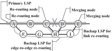
In link re-routing, a backup LSP is created between the two LSRs at the edges of a link that is to be protected from failure. Link re-routing has the advantage that setting up a single backup LSP provides protection of all LSPs routed through the corresponding link. However, when assurance on the service quality is required, determining the amount of resources to be reserved to the backup LSP is not straightforward because they are going to be shared by several LSPs in case of failure of the link.
18.5.3 MPLS-Based VPNs
A virtual private network (VPN) aims at providing connectivity to private networks through a shared infrastructure while enabling the enforcement of policies as if interconnected through a dedicated infrastructure. At least in principle, the nature of such policies ranges from security, to addressing, to quality of service; the typical application for VPNs is the interconnection of remote corporate sites allowing the same private addressing scheme to be used across the various sites and ensuring isolation of corporate traffic from other traffic traveling on the shared communication infrastructure. The shared infrastructure might be the backbone of a service provider or even the public Internet. Although various solutions are available and being implemented, MPLS enables a scalable, manageable solution for VPNs where the shared infrastructure is the MPLS network of a service provider [28].
Figure 18.15 shows the network architecture for providing VPN services over an MPLS network [28]. A customer edge (CE) router at the edge of a private (corporate) network interconnects to a provider edge (PE) router that is a label edge router in charge of adding an MPLS header with a proper label to packets received from the private network and strips the header of packets to be forwarded to the CE router. Because an MPLS backbone [where (on-the-fly) routing is based on labels (rather than addresses in the IP packet headers)] is used for interconnecting the private networks, deployment of private addresses, possibly duplicated on different corporate networks and in the backbone, does not affect proper packet forwarding. In order to allow the same addresses to be used by more than one corporate network it is connected to, each PE router builds multiple forwarding tables (each one with its FTNs and NHLFEs) called Virtual Routing and Forwarding (VRF), one for each corporate network it is connected to (see Figure 18.15). Consequently, provider edge routers attach to each packet entering the backbone a label looked up in the VRF corresponding to corporate network the packet is coming from, which ensures that the packet is delivered to the appropriate site of the same corporate network, thus guaranteeing separation of traffic among different corporate networks.
Figure 18.15. MPLS-based VPN network architecture.
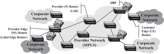
A similar separation must be implemented also in the control plane; that is, when exchanging routing information about the reachability of the various private destinations, advertisements related to different corporate networks must be kept and processed separately. Each PE router gathers information about the corporate networks it is connected to by exchanging routing information, usually through an intradomain protocol such as OSPF, IS-IS, or RIP, with the CE routers it is connected to. Such information is then redistributed across the MPLS backbone reaching all other PE routers connected to CE routers of the same corporate network. To each of the CE routers to which it is connected, PE router must redistribute to only the advertisements concerning destinations of the corporate network to which the CE router belongs. Although different variants for the implementation of MPLS-based VPN services exist, one widely accepted relies on the (preexisting) multiprotocol extensions of the border gateway protocol (BGP) [18] and the definition of a VPN-IPv4 address family to segregate route advertisements pertaining different corporate networks. Addresses of the VPN-IPv4 family are obtained by prepending a 8-byte route distinguisher to each 4-byte IP address. Since each VPN active on the MPLS backbone is assigned a unique route distinguisher, even if different corporate networks deploy the same addresses, their VPN-IPv4 addresses are different. The multiprotocol extensions enable BGP to advertise routes to VPN-IPv4 addresses; and routers can filter advertisements and compute their forwarding table, taking into account the route distinguishers. For example, a PE router will use in the computation of each of its VRFs only the advertisements related to VPN-IPv4 addresses corresponding to one of the corporate networks that the VRF refers to.
Another concern when realizing a large-scale VPN solution is the scalability of routing because, in order to enable dynamic routing, all the destinations of the corporate networks must be advertised through the MPLS backbone in addition to the information on the backbone topology. BGP features help also in this respect. Since BGP messages can be exchanged by routers that are not directly connected, internal routers do not have to participate into the exchange of information about corporate networks that is carried out directly by PE routers. Consequently, internal routers run an intradomain routing protocol, such as OSPF or IS-IS, to gather information exclusively on the MPLS backbone, which limits the size of their data structure and the amount of routing traffic generated. On the other hand, although PE routers participate in the exchange of information about private destinations, their burden is somewhat limited by the fact that they can use the filtering functionalities of BGP to avoid storing and processing locally all the advertisements.
In summary, the BGP/MPLS VPN solution leverages on the flexibility and versatility of the specification and the implementations of BGP to ensure separation of routing information and scalability. Note that BGP can also be used to distribute labels through the MPLS backbone, so LSPs can be properly set up through it to carry traffic among the corporate sites.
Compared to other solutions for the realization of VPN services over IP networks at both the third ISO/OSI level, mostly relying on tunnels based on the encapsulation of IP packets into IP packets and the second ISO/OSI level, mostly relying on setting up a mesh of permanent circuits on a connection-oriented backbone, the BPG/MPLS solution features a high level of automatism stemming from the deployment of the sophisticated routing solution outlined above. As a result, adding new corporate networks requires limited administrative action: Once a new CE router is connected to a PE router, the network administrator needs only to configure the proper VPN identifier to be used as a route distinguisher. The routers, through the exchange of routing information, will automatically discover the destinations on the new corporate site, advertise them to the other sites of the same corporate network, and create the needed label bindings in the PE routers and in the internal routers to provide connectivity. Delators of the BGP/MPLS VPN solution criticize that, contrary to other solutions, data traveling through the backbone unencrypted represents a possibly threat to confidentiality. As in many solutions deployed for interconnection of remote networks, including virtual channels on frame relay networks, leased lines on circuit switched networks, virtual circuits on ATM networks, data confidentiality relies on the trust the customer grants to its VPN service provider. For customers or applications that require a higher security level, specific encryption solutions can be implemented on the corporate network—that is, beyond the scope and the support of VPN provisioning.
18.5.4 MPLS and Quality of Service Support
Independently of the specifics of a solution, providing deterministic quality entails an initial negotiation or signaling phase in which the “network user,” possibly an application, specifies the quality parameters required when transferring data through the network. During this phase the network verifies whether it has sufficient resources to satisfy the request and possibly reserves such resources to the traffic generated by the application. This operational procedure does not fit with the traditional IP paradigm according to which (i) a host wanting to transfer packets through the network simply transmits them without prior negotiation and (ii) each packet represents a stand-alone unit that travels through the network on a route not necessarily related to the one followed by previous and following packets generated by the same host or application. While statement (i) clearly contrasts with the principle of negotiating quality of service (QoS) parameters and reserving resources before transmitting, statement (ii) potentially makes useless the resource reservations made through the network because (some of the) packets might take a different route than the one along which resources have been reserved. These issues have worked around in the Integrated Services (IntServ) [19] architecture by introducing the Resource Reservation Protocol (RSVP) [18] to perform the initial negotiation phase and a complex mechanism called route pinning to ensure that all packets are actually routed through the network nodes that have reserved resources for their flow.
The basic principles underlying MPLS are instead more in line with the basic operational requirements of QoS support, even through MPLS has not been explicitly designed for this purpose since the aim of the MPLS Working Group design effort was to produce a routing, not a QoS, solution. Specifically, although in the topology-based label binding mode no explicit and coordinated signaling is used, MPLS includes the concept of creating an LSP before transferring data through the network and the architecture encompasses mechanisms and protocols to do so. Moreover, all packets belonging to the same FEC are handled the same way and specifically are routed through the same route.
In summary, although MPLS was not designed as a QoS solution and is not used as such, its basic underlying principles are compatible with it and potentially facilitate QoS support.
18.5.5 MPLS and Differentiated Services
Although QoS support, in the sense of providing a deterministic service with resources dedicated to a specific application or data flow as in an integrated services network [19], is not implemented today over the Internet and IP/MPLS networks, the provision of services more sophisticated than the traditional best-effort one is of great importance. Service differentiation, based on the Differentiated Services (DiffServ) architecture [12], is at the basis of this and in traditional IP networks it relies on a field in the IP header whose value identifies the traffic class to which a packet belongs. Each router might handle the packet in a specific way based on the content of this field, called Type of Service (ToS) in the original IP specification and renamed DS Field in the context of the DiffServ architecture. Although this does not ensure that packets generated by a given application receive a specific service with known quality parameters, as in the IntServ approach, packets belonging to applications that need a different service might be handled differently from the others by routers. For example, when a router is congested and needs to discard packets, it tries to discard only packets belonging to classes for which loss is acceptable. Although this does not guarantee that packets belonging to such classes are not lost, it ensures a lower probability of loss with respect to other classes. Moreover, if it is ensured that the amount of traffic belonging to that class is small compared to the overall capacity of the network, packets belonging to such class in fact experience a small or null loss probability, independently of the amount of other types of traffic and loss probability experienced by their packets.
Due to the low complexity of its implementation and deployment, the DiffServ solution is widely used today to provide different levels of service to customers willing to pay a different service fee and, by limiting the amount of traffic of a given service class, to guarantee a certain service (e.g., delay below a given threshold and loss probability below a given threshold). In traditional IP networks, traffic is limited through network engineering, namely by limiting the number of users (generating traffic of a specific service class) and the amount of traffic each user can transmit. This has very low efficiency because being based on (almost) worst-case scenarios, some parts of the network might turn out to be heavily underutilized.
MPLS with its traffic traffic engineering capability enables efficiency to be improved; for example, when traffic of a given class has reached the maximum acceptable level on a certain link, route, or area of the network, part of it can be diverted on a different route. In other words, the combination of MPLS and DiffServ enables per-class traffic engineering through which higher efficiency can be achieved in the utilization of the network when provisioning services with assured quality.
Notes
1 The MPLS forum later merged with into the MPLS/FR Alliance, which in 2008 joined the DSL Forum into the Broadband Forum [4].
2 Note that although the architecture is here described as “future,” it is already being used by a number of operators.
3 Actually, in MPLS the scope of a label might include several input links to a switch, as explained in more detail in Section 18.2.2. However, the underlying concept and advantages are analogous.
4 Although the role of MPLS in both applications is presented in Section 18.5, the deployment of hierarchical LSPs is not discussed because it would require a level of understanding of the solution that is beyond the scope of this chapter.
5 An example of dependency is two nodes sharing the same power supply, or two links whose cables cross the same duct. Dependency among network elements is fundamental when choosing the path for a LSP to be used as a backup to another one in fast fault recovery, as discussed in Section 18.5.2.
6 IP originated from a research funded by the Defense Advanced Research Projects Agency (DARPA) to design a network capable of adapting to topological changes due to failures of links and nodes, as it could be in wartime or in a battlefield.
7 Besides the primary and backup path not sharing any LSR and link, their elements must be independent. For example, LSRs of the backup path should not share power supply with any LSR of the primary path and no link on the backup path should not be contained in a duct containing also a link of the primary path.
REFERENCES
1. The ATM Forum, ATM User–Network Interface Specification-Version 3.1, September 1994.
2. International Telecommunication Union–Telecommunication Standardization Sector (ITU-T), http://www.itu.int/ITU-T/.
3. International Telecommunications Union, ISDN Data Link Layer Specification for Frame Mode Bearer Services, ITU-T Recommendation Q.922, 1992.
4. Broadband Forum, http://www.broadband-forum.org.
5. Cisco Systems, Tag switching, in Internetworking Technology Handbook, available on-line at http://www.cisco.com/en/US/docs/internetworking/technology/handbook/Tag-Switching.html.
6. D. Katz et al., Tag switching architecture—Overview, Internet Drafts, IETF, 1997.
7. ITU-T, Architecture for the Automatically Switched Optical Network (ASON), Recommendation G.8080/ Y.1304, November 2001 (and Revision, January 2003).
8. D. Awduche and Y. Rekhter, Multiprotocol lambda switching: Combining MPLS traffic engineering control with optical crossconnects, IEEE Communi. Maga., Vol. 39, No. 3, pp. 111–116, March 2001.
9. G. Swallow, J. Drake, H. Ishimatsu, and Y. Rekhter, Generalized Multiprotocol Label Switching (GMPLS) User–Network Interface (UNI): Resource ReserVation Protocol-Traffic Engineering (RSVP-TE) Support for the Overlay Model, RFC 4208, Standards Track, October 2005.
10. IETF, The Internet Engineering Task Force (IETF), http://www.ietf.org.
11. E. Rosen, D. Tappan, G. Fedorkow, Y. Rekhter, D. Farinacci, T. Li, and A. Conta, MPLS Label Stack Encoding, RFC 3032, Standards Track, January 2001.
12. S. Blake, D. Black, M. Carlson, E. Davies, Z. Wang, and W. Weiss, An Architecture for Differentiated Services, RFC 2475, Standard Tracks, December 1998.
13. F. Le Faucheur et al., Multi-Protocol Label Switching (MPLS) Support of Differentiated Services, RFC 3270, Standards Track, May 2002.
14. B. Davie, J. Lawrence, K. McCloghrie, Y. Rekhter, E. Rosen, and G. Swallow, MPLS Using LDP and ATM VC Switching, RFC 3035, Standards Track, January 2001.
15. A. Conta, P. Doolan, and A. Malis, Use of Label Switching on Frame Relay Networks Specification, RFC 3034, Standards Track, January 2001.
16. E. Rosen, A. Viswanathan, and R. Callon, Multiprotocol Label Switching Architecture, RFC 3031, Standards Track, January 2001.
17. Y. Rekhter, T. Li, and S. Hares (eds.), A Border Gateway Protocol 4 (BGP-4), Standards Track, RFC 4271, January 2006.
18. R. Braden (ed.), L. Zhang, S. Berson, S. Herzog, and S. Jamin, Resource ReSerVation Protocol (RSVP)—Version 1 Functional Specification, RFC 2205, Standards Track, September 1997.
19. R. Braden, D. Clark, and S. Shenker, Integrated Services in the Internet Architecture: An Overview, RFC 1633, Informational, June 1994.
20. D. Awduche, L. Berger, D. Gan, T. Li, V. Srinivasan, and G. Swallow, RSVP-TE: Extensions to RSVP for LSP Tunnels, RFC 3209, Standards Track, December 2001.
21. L. Andersson, P. Doolan, N. Feldman, A. Fredette, and B. Thomas, LDP Specification, RFC 3036, January 2001.
22. IETF MPLS Working Group, Multiprotocol Label Switching, http://www.ietf.org/html.charters/mpls-charter.html.
23. J. Moy, OSPF Version 2, RFC 2328—STD 54, April 1998.
24. R. W. Callon, Use of OSI IS-IS for Routing in TCP/IP and Dual Environments, RFC 1195, Standards Track, December 1990.
25. K. Ishiguro, V. Manral, A. Davey, and A. Lindem (ed.), Traffic Engineering Extensions to OSPF Version 3, RFC 5329, Standards Track, September 2008.
26. T. Li and H. Smit, IS-IS Extensions for Traffic Engineering, RFC 5305, Standards Track, October 2008.
27. B. Jamoussi, (ed.), L. Andersson, R. Callon, R. Dantu, L. Wu, P. Doolan, T. Worster, N. Feldman, A. Fredette, M. Girish, E. Gray, J. Heinanen, T. Kilty, and A. Malis, Constraint-Based LSP Setup Using LDP, RFC 3212, Standards Track, January 2002.
28. E. Rosen and Y. Rekhter, BGP/MPLS IP Virtual Private Networks (VPNs), RFC 4364, Standards Track, February 2006.