Basic Science of the Fouling Process
Abstract
Chapter 2 reviews the science of the fouling process. The basic fouling mechanisms—crystallization, particulate, chemical reaction, corrosion, and biological fouling—are described with particular focus on the mechanisms underlying crude oil fouling: chemical reaction and corrosion fouling. Possible routes of formation of crude oil fouling deposits are then discussed. These include autoxidation, corrosion, polymerization, thermal cracking, and asphaltene precipitation. Several events occurring in fouling—initiation, transport, attachment, removal, and ageing—are also discussed. Finally, the chapter reviews the effects that key variables such as crude oil composition, operating conditions, and surface conditions have on these events.
Keywords
Asphaltene precipitation; Autoxidation; Corrosion; Crude oil compatibility; Crude oil fouling; Events in fouling; Fouling mechanisms; Fouling science; Variables affecting fouling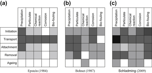
2.1. Fouling Mechanisms
2.2. Routes to Crude Oil Fouling Formation
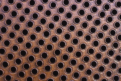
2.2.1. Corrosion
![]()
![]()
![]()
![]()
![]()
![]()
![]()
2.2.2. Autoxidation
![]()
![]()
![]()
![]()
![]()
![]()
![]()
![]()
![]()
![]()
2.2.3. Polymerization
![]()
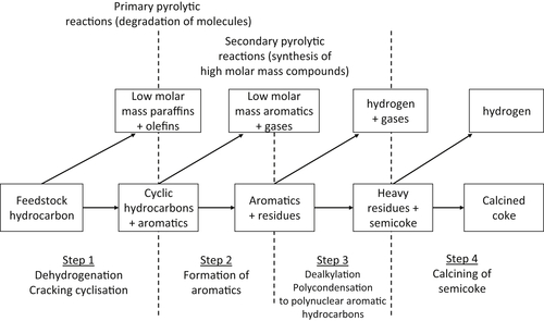
2.2.4. Thermal Cracking
![]()
![]()
![]()
![]()
![]()
![]()
![]() (2.1)
(2.1)
2.2.5. Asphaltene Precipitation
![]() (2.2)
(2.2)
2.2.6. Generalised mechanism
![]()
2.3. Events in Crude Oil Fouling
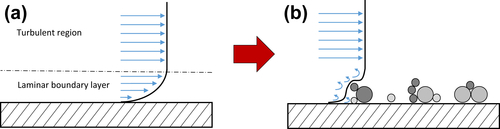
2.3.1. Initiation
![]() (2.3)
(2.3)
![]() (2.4)
(2.4)
![]() (2.5)
(2.5)
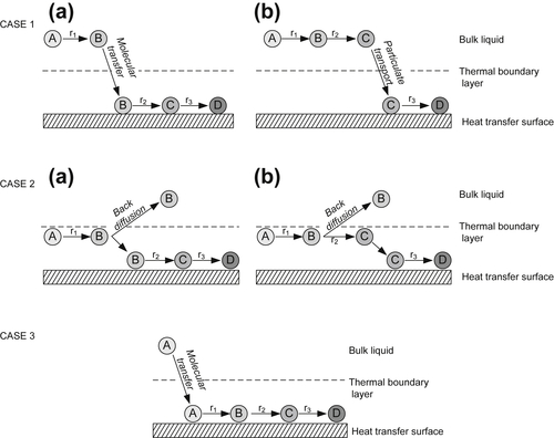
2.3.2. Transport
![]() (2.6)
(2.6)
![]() (2.7)
(2.7)
![]() (2.8)
(2.8)
![]() (2.9)
(2.9)
2.3.3. Attachment
2.3.4. Removal
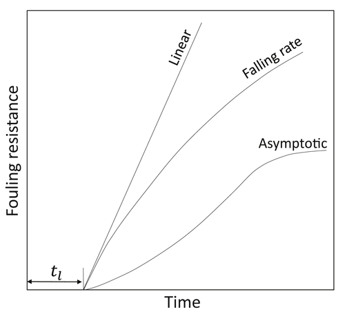
2.3.5. Ageing
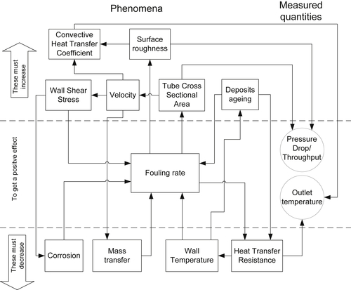
2.4. Variables Affecting Fouling
2.4.1. Crude Oil Composition and Inorganic Contaminants
2.4.1.1. Oxygen
2.4.1.2. Sulfur
2.4.1.3. Metals
2.4.1.4. Asphaltenes
2.4.2. Temperature
![]() (2.10)
(2.10)
2.4.3. Velocity and Shear Stress
2.4.4. Surface Conditions and Roughness Dynamics